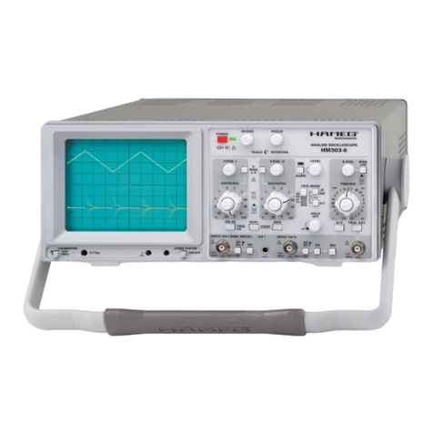
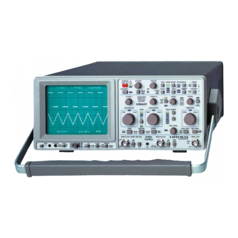
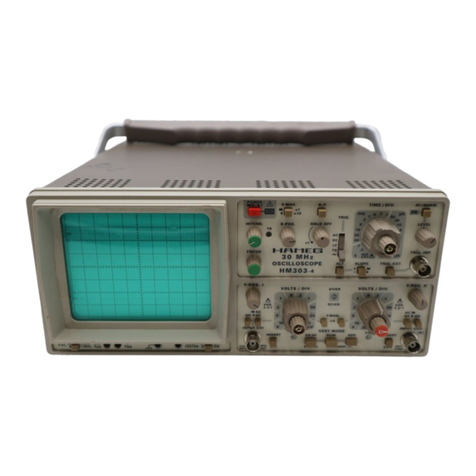
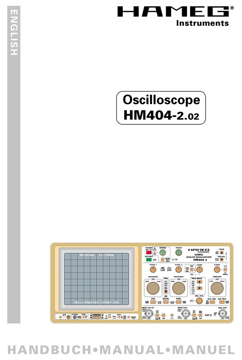
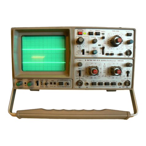
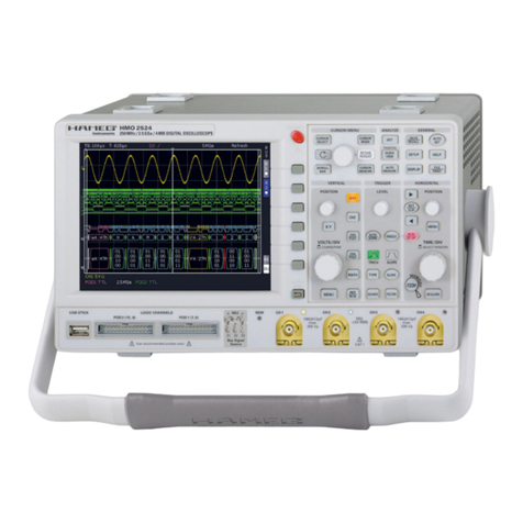
Hameg HM504-2 User manual

Form 080/01
Complimentary Reference Material
This PDF has been made available as a complimentary service for you to assist in
evaluating this model for your testing requirements.
T G offers a wide range of test equipment solutions, from renting short to long
term, buying refurbished and purchasing new. Financing options, such as
Financial Rental, and Leasing are also available on application.
T G will assist if you are unsure whether this model will suit your requirements.
Call T G if you need to organise repair and/or calibrate your unit.
If you click on the “Click-to-Call” logo below, you can all us for FREE!
TMG Corporate Website TMG Products Website
Disclaimer:
All trademarks appearing within this PDF are trademarks of their respective owners.


Oscilloscope
HM504-2
Manual
English

Subject to change without notice
2
CE-Declaration of Conformity ........................................... 4
General Information regarding the CE-marking .............. 4
Specifications ...................................................................... 5
General Information ........................................................... 6
Symbols ............................................................................ 6
Use of tilt handle .............................................................. 6
Safety ............................................................................... 6
Intended purpose and operating conditions .................... 6
EMC ................................................................................. 7
Warranty ........................................................................... 7
Maintenance .................................................................... 7
Protective Switch-Off ....................................................... 7
Power supply .................................................................... 7
Type of signal voltage .................................................... 8
Amplitude Measurements ............................................... 8
Total value of input voltage .............................................. 9
Time Measurements........................................................ 9
Rise Time Measurement .................................................. 10
Connection of Test Signal................................................. 10
Controls and Readout ........................................................ 11
A: Menu Display and Operation ....................................... 11
B: READOUT Information................................................. 12
C: Descriptions of Controls .............................................. 12
Menu .................................................................................... 23
FirstTime Operation ........................................................... 24
Trace Rotation TR ............................................................. 24
Probe compensation and use .......................................... 24
Adjustment at 1 kHz ......................................................... 24
Adjustment at 1 MHz ....................................................... 24
Operating modes of the vertical
amplifiers in Yt mode. ........................................................ 25
X-Y Operation ................................................................... 25
Phase comparison with Lissajous figures ....................... 26
Phase difference measurement
in DUAL mode (Yt) ........................................................... 26
Phase difference measurement in DUAL mode .............. 26
Measurement of an amplitude modulation ..................... 26
Triggering and time base ................................................... 27
Automatic Peak (value) -Triggering ................................... 27
Normal Triggering ............................................................. 28
SLOPE ....................................................................... 28
Trigger coupling ................................................................ 28
Triggering of video signals ............................................... 28
Line / Mains triggering (~) ................................................ 29
Alternate triggering .......................................................... 29
External triggering ............................................................ 29
Trigger indicator ”TR” ...................................................... 30
HOLD OFF-time adjustment ............................................ 30
Delay / After Delay Triggering ........................................... 30
AUTO SET ............................................................................ 32
Mean Value Display ............................................................ 32
ComponentTester ............................................................... 33
General ............................................................................. 33
Using the Component Tester ........................................... 33
Test Procedure ................................................................. 33
Test Pattern Displays ........................................................ 33
Testing Resistors .............................................................. 33
Testing Capacitors and Inductors..................................... 33
Testing Semiconductors .................................................. 34
Testing Diodes .................................................................. 34
Testing Transistors ............................................................ 34
In-Circuit Tests .................................................................. 34
Adjustments ........................................................................ 35
RS-232 Interface - Remote Control ................................... 35
Safety ............................................................................... 35
Operation ......................................................................... 35
RS-232 Cable .................................................................... 35
RS-232 protocol................................................................ 35
Baud-Rate Setting ............................................................ 35
Data Communication ....................................................... 35
Front Panel HM504-2 .......................................................... 36
Oscilloscope
HM504-2
3
3
Contents

3
Subject to change without notice
General information regarding the CE marking
HAMEG instruments fulfill the regulations of the EMC directive. The conformity test made by HAMEG is based on the actual
generic- and product standards. In cases where different limit values are applicable, HAMEG applies the severer standard.
For emission the limits for residential, commercial and light industry are applied. Regarding the immunity (susceptibility)
the limits for industrial environment have been used. The measuring- and data lines of the instrument have much influence
on emmission and immunity and therefore on meeting the acceptance limits. For different applications the lines and/or
cables used may be different. For measurement operation the following hints and conditions regarding emission and im-
munity should be observed:
1. Data cables
For the connection between instruments resp. their interfaces and external devices, (computer, printer etc.) sufficiently
screened cables must be used. Without a special instruction in the manual for a reduced cable length, the maximum cable
length of a dataline must be less than 3 meters and not be used outside buildings. If an interface has several connectors
only one connector must have a connection to a cable. Basically interconnections must have a double screening. For IEEE-
bus purposes the double screened cables HZ72S and HZ72L from HAMEG are suitable.
2. Signal cables
Basically test leads for signal interconnection between test point and instrument should be as short as possible. Without
instruction in the manual for a shorter length, signal lines must be less than 3 meters and not be used outside buildings.
Signal lines must screened (coaxial cable - RG58/U). A proper ground connection is required. In combination with signal
generators double screened cables (RG223/U, RG214/U) must be used.
3. Influence on measuring instruments
Under the presence of strong high frequency electric or magnetic fields, even with careful setup of the measuring equip-
ment an influence of such signals is unavoidable. This will not cause damage or put the instrument out of operation. Small
deviations of the measuring value (reading) exceeding the instruments specifications may result from such conditions in
individual cases.
4. RF immunity of oscilloscopes
4.1 Electromagnetic RF field
The influence of electric and magnetic RF fields may become visible (e.g. RF superimposed), if the field intensity is high. In
most cases the coupling into the oscilloscope takes place via the device under test, mains/line supply, test leads, control
cables and/or radiation. The device under test as well as the oscilloscope may be effected by such fields. Although the in-
terior of the oscilloscope is screened by the cabinet, direct radiation can occur via the CRT gap. As the bandwidth of each
amplifier stage is higher than the total –3dB bandwidth of the oscilloscope, the influence RF fields of even higher frequen-
cies may be noticeable.
4.2 Electrical fast transients / electrostatic discharge
Electrical fast transient signals (burst) may be coupled into the oscilloscope directly via the mains/line supply, or indirectly
via test leads and/or control cables. Due to the high trigger and input sensitivity of the oscilloscopes, such normally high
signals may effect the trigger unit and/or may become visible on the CRT, which is unavoidable. These effects can also be
caused by direct or indirect electrostatic discharge.
HAMEG Instruments GmbH
KONFORMITÄTSERKLÄRUNG
DECLARATION OF CONFORMITY
DECLARATION DE CONFORMITE
Herstellers HAMEG Instruments GmbH
Manufacturer Industriestraße 6
Fabricant D-63533 Mainhausen
Die HAMEG Instruments GmbH bescheinigt die Konformität für das Produkt
The HAMEG Instruments GmbH herewith declares conformity of the product
HAMEG Instruments GmbH déclare la conformite du produit
Bezeichnung / Product name / Designation:
Oszilloskop/Oscilloscope/Oscilloscope
Typ /Type /Type: HM504-2
mit / with / avec: –
Optionen / Options / Options: –
mit den folgenden Bestimmungen / with applicable regulations / avec les
directives suivantes
EMV Richtlinie 89/336/EWG ergänzt durch 91/263/EWG, 92/31/EWG
EMC Directive 89/336/EEC amended by 91/263/EWG, 92/31/EEC
Directive EMC 89/336/CEE amendée par 91/263/EWG, 92/31/CEE
Niederspannungsrichtlinie 73/23/EWG ergänzt durch 93/68/EWG
Low-Voltage Equipment Directive 73/23/EEC amended by 93/68/EEC
Directive des equipements basse tension 73/23/CEE amendée par 93/68/CEE
Angewendete harmonisierte Normen / Harmonized standards applied / Normes
harmonisées utilisées
Sicherheit / Safety / Sécurité
EN 61010-1: 2001 / IEC (CEI) 1010-1: 2001
Messkategorie / Measuring category / Catégorie de mesure: I
Verschmutzungsgrad / Degree of pollution / Degré de pollution: 2
Elektromagnetische Verträglichkeit / Electromagnetic compatibility /
Compatibilité électromagnétique
EN 61326-1/A1 :1997 + A1:1998 + A2 :2001/IEC 61326 :1997 + A1 :1998 + A2 :2001
Störaussendung / Radiation / Emission:Tabelle / table / tableau 4; Klasse / Class /Classe B.
Störfestigkeit / Immunity / Imunitee:Tabelle / table / tableau A1.
EN 61000-3-2/A14
Oberschwingungsströme / Harmonic current emissions / Émissions de courant
harmonique: Klasse / Class / Classe D.
EN 61000-3-3
Spannungsschwankungen u. Flicker / Voltage fluctuations and flicker / Fluctuations
de tension et du flicker.
Datum / Date / Date Unterschrift / Signature / Signatur
25.6.2003
G. Hübenett
Product Manager
cable HZ72 from HAMEG is suitable.

Subject to change without notice
4
HM504-2
2 Channels with deflection coefficients of 1 mV/cm – 20 V/cm
Time Base: 0.5s/cm – 50 ns/cm,
with X Magnification to 10 ns/cm
Low Noise Measuring Amplifiers with high pulse fidelity
Triggering from 0 to 100 MHz from 5mm signal level
Time Base delay provide high X Magnification
of any portion of the signal
100 MHz 4-Digit Frequency Counter,
Cursor and Automatic Measurement
Save/Recall Memories for Instrument Settings
Readout, Autoset, no Fan
Yt, XY and component-test modes
RS-232 Interface (for parameter queries and control only)
Optimum deflection linearity
Rise-time measurement
with cursors
Full screen display of
50 MHz sine wave
50 MHz Analog Oscilloscope
HM504-2
HM504-2

5
Subject to change without notice
Specifications
50 MHz Analog Oscilloscope HM504-2
Valid at 23 °C after a 30 minute warm-up period
Vertical Deflection
Operating Modes: Channel I or II only
Channels I and II (alternate or chopped)
Sum or Difference of CH I and CH II
Invert: CH II
XY Mode: CH I (X) and CH II (Y)
Bandwidth: 2 x 0 - 50 MHz (-3 dB)
Rise Time: ‹7ns
Deflection Coefficient: 1-2-5 Sequence
1 mV/div. – 2 mV/div.: ± 5 % (0 – 10 MHz (-3 dB))
5 mV/div. – 20 V/div.: ± 3 % (0 – 50 MHz (-3 dB))
Variable (uncalibrated): › 2.5:1 to › 50 V/div.
Input Impedance: 1 MΩ II 15 pF
Input Coupling: DC, AC, GND (ground)
Max. Input Voltage: 400 V (DC + peak AC)
Triggering
Automatic (Peak to Peak): 20 Hz – 100 MHz (≥5 mm)
Normal with Level Control: 0 – 100 MHz (≥5 mm)
Slope: positive or negative
Sources: Channel I or II, CH I/CH II alternate (≥8 mm),
Line and External
Coupling: AC (10 Hz – 100 MHz), DC (0 –100 MHz),
HF (50 kHz –100 MHz), LF (0 –1.5 kHz)
Trigger Indicator: LED
Triggering after Delay: with Level Control and Slope selection
External Trigger Signal: ≥0.3 Vpp (0 – 50 MHz)
Active TV sync. separator: Field and Line, +/-
Horizontal Deflection
Time Base: 0.5 s/div. – 50 ns/div. (1-2-5 Sequence)
Accuracy: ± 3 %
Variable (uncalibrated): › 2.5 :1 to › 1.25 s/div.
X Magnification x 10: up to 10 ns/div. (± 5 %)
Accuracy: ± 5 %
Delay (selectable): 140 ms – 200 ns (variable)
Hold-Off Time: variable to approx. 10 : 1
XY
Bandwidth X amplifier: 0 – 3 MHz (-3 dB)
XY Phase shift ‹ 3°: ‹ 120 kHz
Operation / Readout / Control
Manual: via controls
Autoset: automatic signal related parameter settings
Save and Recall: 9 instrument parameter settings
Readout: display of menu, parameters, cursors and
results
Autom. Measurement: Freq./Period, Vdc, Vpp, Vp+, Vp-,
Trigger Level
Cursor Measurement: Δt, 1/Δt, tr, ΔV, V to GND, Gain, Ratio X and Y
Frequency counter: 4 digit (0.01 % ± 1 digit) 0.5 Hz – 100 MHz
Interface (standard fitting): RS-232 (for control)
Component Tester
Test Voltage: approx. 7 Vrms (open circuit)
Test Current: max. 7 mArms (short-circuit)
Test Frequency: approx. 50 Hz
Test Connection: 2 banana jacks 4 mm Ø
One test circuit lead is grounded via protective earth (PE)
Miscellaneous
CRT: D14-363GY, 8 x 10 cm with internal graticule
Acceleration Voltage: approx. 2 kV
Trace Rotation: adjustable on front panel
Z-input (Intens. modulation): max. + 5 V (TTL)
Calibrator Signal (Square Wave):0.2V ± 1 %, 1 Hz – 1 MHz (tr ‹ 4 ns), DC
Power Supply (Mains): 105 – 253V, 50/60 Hz ± 10 %, CAT II
Power Consumption: approx. 34 Watt at 230V/50 Hz
Ambient temperature: 0° C...+ 40° C
Safety class: Safety class I (EN61010-1)
Weight: approx. 5.4 kg
Dimensions (W x H x D): 285 x 125 x 380 mm
Accessories supplied: Line Cord, Operators Manual and Software for Windows
on CD-ROM, 2 Probes 1:1/10:1 (HZ154)
Optional accessories:
HZ70 Opto Interface (with optical fiber cable)
HM504-2E/140408/ce · Subject to alterations · © HAMEG Instruments GmbH · ® Registered Trademark · DQS-certified in accordance with DIN EN ISO 9001:2000, Reg.-No.: DE-071040 QM
HAMEG Instruments GmbH · Industriestr. 6 · D-63533 Mainhausen · Tel +49 (0) 6182 800 0 · Fax +49 (0) 6182 800 100 · www.hameg.com · info@hameg.com
A Rohde & Schwarz Company
www.hameg.com

Subject to change without notice
6
General information
A
A
B
B
C
C
D
D
E
E
T
F
PUkT
PUkT
PUk PUk PUk PUk PUk PUk
PUkT
PUkT PUkT
PUkT
HGOPFFD
PUkT
HGOFFD
PUOPFGkT
INPUTCHI
OPK
HJ
VBN
HJKL
INPUTCHI
OPK
HJ
VBN
HJKL
INPUTCHI
OPK
HJ
VBN
HJKL
PUkT
PUkT
PUOPFGkT PUOPFGkT
PUOPFGkT
PUOPFGkT
PUOPFGkT PUOPFGkT
PUOPFGkT PUOPFGkT
PUOPFGkTPUOPFGkTPUOPFGkT PUOPFGkT
HM507
PUOPFGkTPUOPFGkT
PUOPFGkT PUOPFGkT PUOPFGkT PUOPFGkT
PUOPFGkT PUOPFGkT
PUOGkT
HAMEG
B
T
T
Safe operation may be endangered if any of the following
was noticed:
– in case of visible damage.
– in case loose parts were noticed
– if it does not function any more.
– after prolonged storage under unfavourable conditions (e.g.
like in the open or in moist atmosphere).
– after any improper transport (e.g. insufficient packing not
conforming to the minimum standards of post, rail or transport
company)
Proper operation
Please note: This instrument is only destined for use by personnel
well instructed and familiar with the dangers of electrical measure-
ments.
For safety reasons the oscilloscope may only be operated from
mains outlets with safety ground connector. It is prohibited to
separate the safety ground connection. The plug must be inserted
prior to connecting any signals.
General information
Please check the instrument for mechanical damage or loose
parts immediately after unpacking. In case of damage we advise
to contact the sender. Do not operate.
List of symbols used
Consult the manual High voltage
STOP
Important note Ground
Positioning the instrument
As can be seen from the figures, the handle can be set into diffe-
rent positions:
A and B = carrying
C = horizontal operating
D and E = operating at different angles
F = handle removal
T = shipping (handle unlocked)
STOP
Attention!
When changing the handle position, the instru-
ment must be placed so that it can not fall (e.g.
placed on a table). Then the handle locking knobs
must be simultaneously pulled outwards and
rotated to the required position. Without pulling
the locking knobs they will latch in into the next
locking position.
Handle mounting/dismounting
The handle can be removed by pulling it out further, depending on
the instrument model in position B or F.
Safety
The instrument fulfils the VDE 0411 part 1 regulations for
electrical measuring, control and laboratory instruments and
was manufactured and tested accordingly. It left the factory in
perfect safe condition. Hence it also corresponds to European
Standard EN 61010-1 resp. International Standard IEC 1010-1.
In order to maintain this condition and to ensure safe operation
the user is required to observe the warnings and other directions
for use in this manual. Housing, chassis as well as all measu-
ring terminals are connected to safety ground of the mains.
All accessible metal parts were tested against the mains with
200 VDC. The instrument conforms to safety class I.
The oscilloscope may only be operated from mains outlets with a
safety ground connector. The plug has to be installed prior to con-
necting any signals. It is prohibited to separate the safety ground
connection.
Most electron tubes generate X-rays; the ion dose rate of this ins-
trument remains well below the 36 pA/kg permitted by law.
In case safe operation may not be guaranteed do not use the ins-
trument any more and lock it away in a secure place.

7
Subject to change without notice
General information
Type of fuse:
Size 5 x 20 mm; 250V~, C;
IEC 127, Bl. III; DIN 41 662
(or DIN 41 571, Bl. 3).
Cut off: slow blow (T) 0,8A.
CAT I
This oscilloscope is destined for measurements in circuits not
connected to the mains or only indirectly. Direct measurements,
i.e. with a galvanic connection to circuits corresponding to the
categories II, III, or IV are prohibited!
The measuring circuits are considered not connected to the mains
if a suitable isolation transformer fulfilling safety class II is used.
Measurements on the mains are also possible if suitable probes
like current probes are used which fulfil the safety class II. The
measurement category of such probes must be checked and
observed.
Measurement categories
The measurement categories were derived corresponding to the
distance from the power station and the transients to be expected
hence. Transients are short, very fast voltage or current excursions
which may be periodic or not.
Measurement CAT IV:
Measurements close to the power station, e.g. on electricity
meters
Measurement CAT III:
Measurements in the interio r of buildi ngs ( p ower dis tri buti on instal-
lations, mains outlets, motors which are permanently installed).
Measurement CAT II:
Measurements in circuits directly connected to the mains (house-
hold appliances, power tools etc).
Measurement CAT I:
Electronic instruments and circuits which contain circuit breakers
resp. fuses.
Environment of use.
The oscilloscope is destined for operation in industrial, business,
manufacturing, and living sites.
Environmental conditions
Operating ambient temperature: 0 to + 40 degrees C. During trans-
port or storage the temperature may be –20 to +55 degrees C.
Please note that after exposure to such temperatures or in case
of condensation proper time must be allowed until the instrument
has reached the permissible range of 0 to + 40 degrees resp. until
the condensation has evaporated before it may be turned on!
Ordinarily this will be the case after 2 hours. The oscilloscope is
destined for use in clean and dry environments. Do not operate in
dusty or chemically aggressive atmosphere or if there is danger
of explosion.
The operating position may be any, however, sufficient ventilation
mustbeensured(convectioncooling). Prolonged operationrequires
the horizontal or inclined position.
STOP
Do not obstruct the ventilation holes!
Specifications are valid after a 20 minute warm-up period between
15 and 30 degr. C. Specifications without tolerances are average
values.
Warranty and repair
HAMEG instruments are subjected to a strict quality control. Prior
to leaving the factory, each instrument is burnt-in for 10 hours.
By intermittent operation during this period almost all defects
are detected. Following the burn-in, each instrument is tested for
function and quality, the specifications are checked in all operating
modes; the test gear is calibrated to national standards.
The warranty standards applicable are those of the country in
which the instrument was sold. Reclamations should be directed
to the dealer.
Only valid in EU countries
In order to speed reclamations customers in EU countries may
also contact HAMEG directly. Also, after the warranty expired, the
HAMEG service will be at your disposal for any repairs.
Return material authorization (RMA):
Prior to returning an instrument to HAMEG ask for a RMA number
either by internet (http://www.hameg.com) or fax. If you do not
have an original shipping carton, you may obtain one by calling the
HAMEG sales dept (+49-6182-800-300) or by sending an email
to vertrieb@hameg.com.
Maintenance
Clean the outer shell using a dust brush in regular intervals. Dirt can
be removed from housing, handle, all metal and plastic parts using
a cloth moistened with water and 1 % detergent. Greasy dirt may
be removed with benzene (petroleum ether) or alcohol, there after
wipe the surfaces with a dry cloth. Plastic parts should be treated
with an antistatic solution destined for such parts. No fluid may
enter the instrument. Do not use other cleansing agents as they
may adversely affect the plastic or lacquered surfaces.
Line voltage
The instrument has a wide range power supply from 105 to 253 V,
50 or 60 Hz ±10%. There is hence no line voltage selector.
The line fuse is accessible on the rear panel and part of the line input
connector. Prior to exchanging a fuse the line cord must be pulled
out. Exchange is only allowed if the fuse holder is undamaged, it
can be taken out using a screwdriver put into the slot. The fuse
can be pushed out of its holder and exchanged.
The holder with the new fuse can then be pushed back in place
against the spring. It is prohibited to ”repair“ blown fuses or to
bridge the fuse. Any damages incurred by such measures will
void the warranty.

Subject to change without notice
8
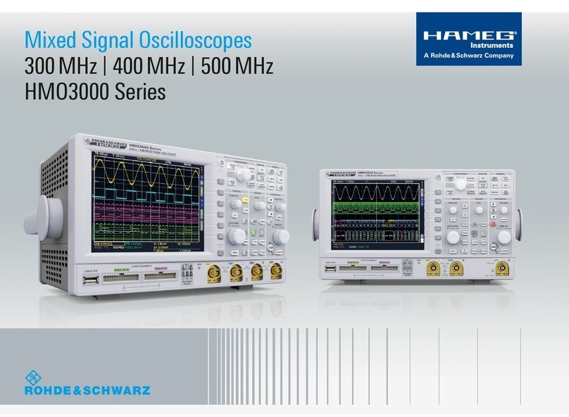
Voltage values of a sine curve
Vrms = effective value; Vp= simple peak or crest value;
Vpp = peak to peak value; Vmom = momentary value.
The minimum signal voltage which must be applied to the Y input
for a trace of 1div height is 1mVpp (± 5%) with this deflection
coefficient displayed on the screen (readout) and the vernier
switched off (VAR-LED dark). However, smaller signals than this
may also be displayed. The deflection coefficients are indicated
in mV/div or V/div (peak to peak value).
The magnitude of the applied voltage is ascertained by multiplying
the selected deflection coefficient by the vertical display height
in div. If an attenuator probe x10 is used, a further multiplication
by a factor of 10 is required to ascertain the correct voltage value.
This factor can be entered into the oscilloscope’s memory for
automatic calculation.
For exact amplitude measurements, the variable control (VAR)
must be set to its calibrated detent CAL position.
With the variable control activated the deflection sensitivity can
be reduced up to a ratio of 2.5 to 1 (
please note ”controls and
readout”
). Therefore any intermediate value is possible within
the 1-2-5 sequence of the attenuator(s).
With direct connection to the Y input, signals up to 400 Vpp
may be displayed (attenuator set to 20 V/div, variable
control to 2.5:1).
With the designations
H = display height in div,
U = signal voltage in Vpp at the Y input,
D = deflection coefficient in V/div at attenuator switch,
the required value can be calculated from the two given quantities:
However, these three values are not freely selectable. They have
to be within the following limits (trigger threshold, accuracy of
reading):
H between 0.5 and 8div, if possible 3.2 to 8div,
U between 0.5 mVpp and 160 Vpp,
D between 1 mV/div and 20 V/div in 1-2-5 sequence.
Examples:
Set deflection coefficient D = 50 mV/div 0.05 V/div,
observed display height H = 4.6 div,
required voltage U = 0.05x4.6 = 0.23 Vpp.
Type of signal voltage
The oscilloscope HM504-2 allows examination of DC voltages
and most repetitive signals in the frequency range up to at least
50 MHz (–3 dB).
The Y amplifiers have been designed for minimum overshoot and
therefore permit a true signal display.
The display of sinusoidal signals within the bandwidth limits
causes no problems, but an increasing error in measurement due
to gain reduction must be taken into account when measuring
high frequency signals. This error becomes noticeable at approx.
14 MHz. At approx. 30 MHz the reduction is approx. 10% and the
real voltage value is 11% higher. The gain reduction error can not
be defined exactly as the –3 dB bandwidth of the Y amplifiers
differs between 50 MHz and 55 MHz.
When examining square or pulse type waveforms, attention
must be paid to the harmonic content of such signals. The
repetition frequency (fundamental frequency) of the signal must
therefore be significantly smaller than the upper limit frequency
of the Y amplifiers.
Displaying composite signals can be difficult, especially if they
contain no repetitive higher amplitude content that can be used
for triggering. This is the case with bursts, for instance. To obtain
a well triggered display in this case, the assistance of the variable
holdoff function or the delayed time base may be required.
Television video signals are relatively easy to trigger using the
built in TV Sync Separator (TV).
For optional operation as a DC or AC voltage amplifier, each Y
amplifier input is provided with a DC/AC switch. DC coupling should
only be used with a series connected attenuator probe or at very
low frequencies, or if the measurement of the DC voltage content
of the signal is absolutely necessary.
When displaying very low frequency pulses, the flat tops may be
sloping with AC coupling of the Y amplifier (AC limit frequency
approx. 1.6 Hz for 3dB). In this case, DC operation is preferred,
provided the signal voltage is not superimposed on too high a DC
level. Otherwise a capacitor of adequate capacitance must be
connected to the input of the Y amplifier with DC coupling. This
capacitor must have a sufficiently high breakdown voltage rating.
DC coupling is also recommended for the display of logic and
pulsesignals,especiallyifthepulsedutyfactorchangesconstantly.
Otherwise the display will move upwards or downwards at each
change. Pure direct voltages can only be measured with DC
coupling.
Amplitude Measurements
In general electrical engineering, alternating voltage data normally
refers to effective values (rms = root mean square value).
However, for signal magnitudes and voltage designations in
oscilloscope measurements, the peak to peak voltage (Vpp) value
is applied. The latter corresponds to the real potential difference
between the most positive and most negative points of a signal
waveform.
If a sinusoidal waveform, displayed on the oscilloscope screen,
is to be converted into an effective (rms) value, the resulting peak
to peak value must be divided by 2 x √2 = 2.83. Conversely, it
should be observed that sinusoidal voltages indicated in Vrms
(Veff) have 2.83 times the potential difference in Vpp. The
relationship between the different voltage magnitudes can be
seen from the following figure.
Type of signal voltage
9
Subject to change without notice
Input voltage U = 5 Vpp,
set deflection coefficient D = 1 V/div,
required display height H = 5:1 = 5 div.
Signal voltage U = 230 Vrms x 2√2 = 651 Vpp
(voltage > 160 Vpp, with probe 10:1: U = 65.1 Vpp),
desired display height H = min. 3.2 div, max. 8 div,
max. deflection coefficient D = 65.1:3.2 = 20.3 V/div,
min. deflection coefficient D = 65.1:8 = 8.1 V/div,
adjusted deflection coefficient D = 10 V/div.
The previous examples are related to the CRT graticule reading.
The results can also be determined with the aid of the DV cursor
measurement (
please note ”controls and readout”
).
The input voltage must not exceed 400 V, irrespective of polarity.
If an AC voltage which is superimposed on a DC voltage is
applied, the maximum peak value of both voltages must not
exceed + or –400 V. So for AC voltages with a mean value of zero
volt the maximum peak to peak value is 800 Vpp.
If attenuator probes with higher limits are used, the probes
limits are valid only if the oscilloscope is set to DC input
coupling.
If DC voltages are applied under AC input coupling conditions the
oscilloscope maximum input voltage value remains 400 V.
The attenuator consists of a resistor in the probe and the
1 MOhm input resistor of the oscilloscope, which is disabled by
the AC input coupling capacity when AC coupling is selected. This
also applies to DC voltages with superimposed AC voltages.
It also must be noted that due to the capacitive reactance of the
AC input coupling capacitor, the attenuation ratio depends on the
signal frequency. For sine wave signals with frequencies higher
than 40 Hz this influence is negligible.
Apart from the above listed exceptions, HAMEG 10:1 probes can
be used for DC measurements up to 600 V or AC voltages (with
a mean value of zero volt) of 1200 Vpp. The 100 :1 probe HZ53
allows for use up to 1200 V DC or 2400 Vpp for AC.
It should be noted that its AC peak value is derated at higher
frequencies. If a normal x10 probe is used to measure high
voltages, there is the risk that the compensation trimmer bridging
the attenuator series resistor will break down, causing damage to
the input of the oscilloscope.
However, if for example only the residual ripple of a high voltage
is to be displayed on the oscilloscope, a normal x10 probe is
sufficient. In this case, an appropriate high voltage capacitor
(approx. 22 - 68nF) must be connected in series with the input tip
of the probe.
With Y-POS. control (input coupling to GD) it is possible to use a
horizontal graticule line as reference line for ground potential
before the measurement. It can lie below or above the horizontal
central line according to whether positive and/or negative
deviations from the ground potential are to be measured.
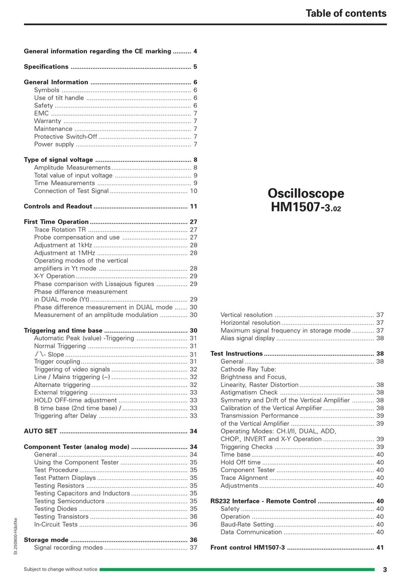
Total value of input voltage
The dotted line shows a voltage alternating at zero volt level. If
superimposed on a DC voltage, the addition of the positive peak
and the DC voltage results in the max. voltage (DC + ACpeak).
Time Measurements
As a rule, most signals to be displayed are periodically repeating
processes, also called periods. The number of periods per second
is the repetition frequency. Depending on the time base setting
(TIME/DIV. knob) indicated by the readout, one or several signal
periods or only a part of a period can be displayed. The time
coefficients are stated in ms/div, µs/div or ns/div. The following
examples are related to the CRT graticule reading. The results can
also be determined with the aid of the Dt and 1/Dt cursor
measurement (
please note ”controls and readout”
).
The duration of a signal period or a part of it is determined by
multiplying the relevant time (horizontal distance in div) by the
(calibrated) time coefficient displayed in the readout.
Uncalibrated,thetimebasespeedcanbereduceduntilamaximum
factor of 2.5 is reached. Therefore any intermediate value is
possible within the 1-2-5 sequence.
With the designations
L = displayed wave length in div of one period,
T = time in seconds for one period,
F = recurrence frequency in Hz of the signal,
Tc = time coefficient in ms, µs or ns/div and the relation
F = 1/T, the following can be stated:
However, these four values are not freely selectable. They
have to be within the following limits:
L between 0.2 and 10 div, if possible 4 to 10 div,
T between 10 ns and 5 s,
F between 0.5 Hz and 100 MHz,
Tc between 100 ns/div and 500 ms/div in 1-2-5 sequence
(with X-MAG. (x10) inactive), and
Tc between 10 ns/div and 50 ms/div in 1-2-5 sequence (with
X-MAG. (x10) active).
Type of signal voltage
Subject to change without notice
10
With a time coefficient of 10 ns/div (X x10 magnification active),
the example shown in the above figure results in a total measured
risetime of
ttot = 1.6 div x 10 ns/div = 16 ns
When very fast risetimes are being measured, the risetimes of
the oscilloscope amplifier and of the attenuator probe have to be
deducted from the measured time value. The risetime of the
signal can be calculated using the following formula.
tr= √ttot2– tosc2– tp2
In this ttot is the total measured risetime, tosc is the risetime of the
oscilloscope amplifier (approx. 7 ns), and tpthe risetime of the
probe (e.g. = 2 ns). If ttot is greater than 100 ns, then ttot can be
taken as the risetime of the pulse, and calculation is unnecessary.
Calculation of the example in the figure above results in a signal
risetime:
tr= √162– 72– 22 = 14.25 ns
The measurement of the rise or fall time is not limited to the trace
dimensions shown in the above diagram. It is only particularly
simple in this way. In principle it is possible to measure in any
display position and at any signal amplitude. It is only important
that the full height of the signal edge of interest is visible in its full
length at not too great steepness and that the horizontal distance
at 10% and 90% of the amplitude is measured. If the edge shows
rounding or overshooting, the 100% should not be related to the
peak values but to the mean pulse heights. Breaks or peaks
(glitches) next to the edge are also not taken into account. With
very severe transient distortions, the rise and fall time
measurementhaslittlemeaning.Foramplifierswithapproximately
constant group delay (therefore good pulse transmission
performance) the following numerical relationship between rise
time tr (in ns) and bandwidth B (in MHz) applies:
Connection ofTest Signal
In most cases, briefly depressing the AUTOSET causes a useful
signal related instrument setting. The following explanations
refer to special applications and/or signals, demanding a manual
instrument setting.
The description of the controls is explained
in the section ”controls and readout”.
Caution:
Whenconnectingunknownsignals totheoscilloscopeinput,
always use automatic triggering and set the input coup-
ling switch to AC. The attenuator should initially be set to
20 V/div.
Sometimes the trace will disappear after an input signal has been
applied.Thenahigherdeflectioncoefficient(lowerinput sensitivity)
must be chosen until the vertical signal height is only 3 – 8 div.
With a signal amplitude greater than 160 Vpp and the deflection
coefficient (VOLTS/DIV.) in calibrated condition, an attenuator
probe must be inserted before the Y input. If, after applying the
signal, the trace is nearly blanked, the period of the signal is
probably substantially longer than the set time deflection
coefficient (TIME/DIV.). It should be switched to an adequately
larger time coefficient.
Examples:
Displayed wavelength L = 7 div,
set time coefficient Tc = 100 ns/div,
thus period T = 7 x 100 x 10-9 = 0.7 µs
thus freq. F = 1/(0.7 x 10-6) = 1.428 MHz.
Signal period T = 1s,
set time coefficient Tc = 0.2 s/div,
thus wavelength L = 1/0.2 = 5 div.
Displayed ripple wavelength L = 1 div,
set time coefficient Tc = 10 ms/div,
thus ripple freq. F = 1/(1 x 10 x 10-3) = 100 Hz.
TV Line frequency F = 15625 Hz,
set time coefficient Tc = 10 µs/div,
required wavelength L = 1/(15,625 x 10-5) = 6.4 div.
Sine wavelength L = min. 4 div, max. 10 div,
Frequency F = 1 kHz,
max. time coefficient Tc = 1/(4 x 103) = 0.25 ms/div,
min. time coefficient Tc = 1/(10 x 103) = 0.1 ms/div,
set time coefficient Tc = 0.2 ms/div,
required wavelength L = 1/(103 x 0.2 x 10-3) = 5 div.
Displayed wavelength L = 0.8 div,
set time coefficient Tc = 0.5 µs/div,
pressed X-MAG. (x10) button: Tc = 0.05 µs/div,
thus freq. F = 1/(0.8 x 0.05 x 10-6) = 25 MHz,
thus period T = 1/(25 x 106) = 40 ns.
If the time is relatively short as compared with the complete
signal period, an expanded time scale should always be applied
(X-MAG. (x10) active). In this case, the time interval of interest
can be shifted to the screen center using the X-POS. control.
RiseTime Measurement
When investigating pulse or square waveforms, the critical
feature is the rise time of the voltage step. To ensure that
transients,ramp-offs,andbandwidthlimitsdonotundulyinfluence
the measuring accuracy, the rise time is generally measured
between 10% and 90% of the vertical pulse height. For
measurement, adjust the Y deflection coefficient using its variab-
le function (uncalibrated) together with the Y-POS. control so that
the pulse height is precisely aligned with the 0% and 100% lines
of the internal graticule. The 10% and 90% points of the signal
will now coincide with the 10% and 90% graticule lines. The
risetime is given by the product of the horizontal distance in div
between these two coincident points and the calibrated time
coefficient setting. The fall time of a pulse can also be measured
by using this method.
The following figure shows correct positioning of the oscilloscope
trace for accurate rise time measurement.
Type of signal voltage

11
Subject to change without notice
With all attenuator probes, the maximum AC input voltage must
be derated with frequency, usually above 20 kHz. Therefore the
derating curve of the attenuator probe type concerned must be
taken into account.
The selection of the ground point on the test object is important
when displaying small signal voltages. It should always be as
close as possible to the measuring point. If this is not done,
serioussignal distortion may result from spurious currents through
the ground leads or chassis parts. The ground leads on attenuator
probes are also particularly critical. They should be as short and
thick as possible. When the attenuator probe is connected to a
BNC-socket, a BNC adapter should be used. In this way ground
and matching problems are eliminated. Hum or interference
appearing in the measuring circuit (especially when a small
deflection coefficient is used) is possibly caused by multiple
grounding because equalizing currents can flow in the shielding
of the test cables (voltage drop between the protective conductor
connections, caused by external equipment connected to the
mains/line, e.g. signal generators with interference protection
capacitors).
Controls and Readout
A: Basic settings
The following description assumes that:
1. “Component Tester” is switched off.
2. The following settings are present under MAIN MENU
> SETUP & INFO > MISCELLANEOUS:
2.1 CONTROL BEEP and ERROR BEEP activated (x),
2.2 QUICK START not activated.
3. The screen Readout is visible.
The LED indicators on the large front panel facilitate operation
and provide additional information. Electrical end positions of
controls are indicated by acoustic signal (beep).
All controls, except the power switch (POWER), are electronically
set and interrogated. Thus, all electronically set functions and
their current settings can be stored and also remotely controlled.
B: Menu Display and Operation
Operation of some pushbuttons activates the display of menus.
There are Standard and Pulldown Menus.
Standard menus:
When a standard menu is displayed, all other readout information
(e.g. parameter settings) are switched off. The readout then
consists of the menu headline, and the respective menu functions.
At the bottom of the graticule are displayed symbols and
commands which can be operated by the pushbuttons related to
them below.
“Esc” CT pushbutton [37] switches one step back in the menu
hierarchy.
“Exit” SELECT – ON/OFF pushbutton [34] closes the menu and
switches back to the operating conditions present before calling
the menu.
The pushbuttons underneath the triangle symbols pointing
upwards UNIT CAL.SEL. [35] and downwards SOURCE GLUE
[33] enable you to select one item which becomes highlighted.
The signal to be displayed can be connected directly to the Y input
of the oscilloscope with a shielded test cable such as HZ32 or
HZ34, or reduced through a x10 or x100 attenuator probe. The
use of test cables with high impedance circuits is only
recommendedforrelativelylowfrequencies(uptoapprox.50 kHz).
For higher frequencies, the signal source must be of low
impedance, i.e. matched to the characteristic resistance of the
cable (as a rule 50 Ohm). Especially when transmitting square and
pulse signals, a resistor equal to the characteristic impedance of
the cable must also be connected across the cable directly at the
Y-input of the oscilloscope. When using a 50 Ohm cable such as
the HZ34, a 50 Ohm through termination type HZ22 is available
from HAMEG. When transmitting square signals with short rise
times, transient phenomena on the edges and top of the signal
may become visible if the correct termination is not used. A
terminating resistance is sometimes recommended with sine
signals as well. Certain amplifiers, generators or their attenuators
maintain the nominal output voltage independent of frequency
only if their connection cable is terminated with the prescribed
resistance. Here it must be noted that the terminating resistor
HZ22 will only dissipate a maximum of 2 Watts. This power is
reached with 10 Vrms (28.3 Vpp) with sine signal. If a x10 or x100
attenuator probe is used, no termination is necessary. In this
case, the connecting cable is matched directly to the high
impedance input of the oscilloscope. When using attenuator
probes, even high internal impedance sources are only slightly
loaded (approx. 10 MOhm II 12 pF or 100 MOhm II 5 pF with
HZ53). Therefore, if the voltage loss due to the attenuation of the
probe can be compensated by a higher amplitude setting, the
probe should always be used. The series impedance of the probe
provides a certain amount of protection for the input of the Y
amplifier. Because of their separate manufacture, all attenuator
probes are only partially compensated, therefore accurate
compensation must be performed on the oscilloscope
(see Probe
compensation )
.
Standard attenuator probes on the oscilloscope normally reduce
its bandwidth and increase the rise time. In all cases where the
oscilloscope bandwidth must be fully utilized (e.g. for pulses with
steep edges) we strongly advise using the probes HZ51 (x10)
HZ52 (x10 HF) and HZ54 (x1 and x10). This can save the purchase
of an oscilloscope with larger bandwidth.
The probes mentioned have an HF-adjustment in addition to low
frequency calibration adjustment. Thus a group delay correction
to the upper limit frequency of the oscilloscope is possible with
the aid of a 1 MHz calibrator, e.g. HZ60.
In fact the bandwidth and rise time of the oscilloscope are not
noticeably changed with these probe types and the waveform
reproduction fidelity can even be improved because the probe
can be matched to the oscilloscope’s individual pulse response.
If a x10 or x100 attenuator probe is used, DC input coupling
must always be used at voltages above 400 V. With AC
coupling of low frequency signals, the attenuation is no
longer independent of frequency, pulse tops can show pulse
tilts. Direct voltages are suppressed but charge the
oscilloscope input coupling capacitor concerned. Its voltage
rating is max. 400 V (DC + peak AC). DC input coupling is
therefore of quite special importance with a x100 atte-
nuation probe which usually has a voltage rating of max.
1200 V (DC + peak AC). A capacitor of corresponding
capacitance and voltage rating may be connected in series
with the attenuator probe input for blocking DC voltage
(e.g. for hum voltage measurement).
Controls and Readout

Subject to change without notice
12
[2] AUTOSET
Briefly pressing this pushbutton results in an automatic
instrument setting selecting Yt mode as the default. The
instrument is set to the last used Yt mode setting (CH I, CH II
or DUAL).
The instrument is set automatically to normal (undelayed)
time base mode, even if the previous Yt mode was present
in combination with search (“sea”), delay (“del”) or triggered
delay (“dTr”) time base mode.
Please also note ”AUTO-
SET” in section “First Time Operation”.
Automatic CURSOR positioning:
If CURSOR lines are displayed and AUTOSET is chosen the
CURSOR lines are set automatically under suitable conditions
and the readout briefly displays “SETTING CURSOR”.
If the signal height is insufficient, the CURSOR lines do not
change. In DUAL mode the CURSOR lines are related to the
signal which is used for internal triggering.
Voltage CURSOR
If voltage measurement is present, the CURSOR lines are
automatically set to the positive and negative peak value of
the signal. The accuracy of this function decreases with
higher frequencies and is also influenced by the signal‘s
pulse duty factor.
Time/Frequency CURSOR
If complex waveforms such as video signals are applied, the
cursor lines may not align exactly with one period and give a
false reading.
[3] INTENS/FOCUS – Knob with associated LEDs and TRACE
ROT.-pushbutton.
If the readout (RO) is not switched off, briefly pressing the
READOUT pushbutton switches over the INTENS/FOCUS
knob function indicated by a LED in the sequence A, FOC,
RO, A. In condition READOUT deactivated, the switching
sequence is A, FOC, A.
“A”:
The INTENS/FOCUS control knob adjusts the signal(s)
intensity. Turning this knob clockwise increases the intensity.
Only the minimum required trace intensity should be used,
depending on signal parameters, oscilloscope settings and
light conditions.
“FOC”:
The INTENS/FOCUS control knob adjusts both the trace and
the readout sharpness. Note: The electron beam diameter
getslargerwithahighertraceintensityandthe trace sharpness
decreases.Thiscanbecorrectedtoacertainextent.Assuming
that the trace sharpness was set to optimum in the screen
centre, it is unavoidable that the trace sharpness decreases
with an increasing distance from the centre.
Since the settings of the signal(s) intensity (A) and the
READOUT (RO) are usually different, the FOCUS should be
set for optimum signal(s) sharpness. The sharpness of the
READOUT then can be improved by reducing the READOUT
intensity.
“RO”:
The INTENS/FOCUS control knob adjusts the READOUT
intensity. Turning this knob clockwise increases and counter
clockwisedecreasestheintensity.Onlytheminimumrequired
intensity should be used.
“SET” MAIN MENU-pushbutton [31] calls the selected menu
item, starts a function or switches a function on/off.
Pulldown menus:
After pressing a pushbutton which calls a Pulldown menu, the
instrument parameter settings are still displayed. The readout
only changes in respect to the called parameter (e.g. input
coupling) and now shows all selectable parameter options (in
case of input coupling: AC, DC and GND). The previously displayed
parameter doesn‘t change but is displayed highlighted. Each time
the pushbutton is briefly pressed the next parameter becomes
active and highlighted, as long as the Pulldown menu is displayed.
Without further pressing the pushbutton, the Pulldown menu
extinguishes after a few seconds and the selected parameter is
displayed in the normal way.
C: READOUT Information
The readout alphanumerically displays the scope parameter
settings, measurement results and CURSOR lines. Which
informationisdisplayeddependsontheactualinstrumentsettings.
The following list contains the most important display information.
Top of the graticule from left to right:
1st time deflection coefficient
2nd trigger source, slope and coupling
3rd operating condition of delay time base
4th measuring results
Bottom of the graticule from left to right:
1st probe symbol (x10), Y deflection coefficient and input
coupling channel I
2nd “+” symbol (addition)
3rd probe symbol (x10), Y deflection coefficient and input
coupling channel II
4th channel mode
The trigger point symbol is displayed at the left graticule border
line. The CURSOR lines can take any position within the graticule.
Description of Controls
The large front panel is, as usual with Hameg oscilloscopes,
marked with several fields.
The following controls and LED indicators are located on the top,
to the right of the screen, above the horizontal line.
[1] POWER – Pushbutton and symbols for ON (I) and OFF (O).
After the oscilloscope is switched on, all LEDs are lit and an
automated instrument test is performed. During this time the
HAMEG logo and the software version are displayed on the
screen. After the internal test is completed successfully, the
overlay is switched off and the normal operation mode is
present. Then the last used settings become activated and
LED [3] indicates the ON condition.
Controls and Readout
POWER
AUTOSET
INTENS / FOCUS
SAVE
RECALL
50 MHz
ANALOG OSCILLOSCOPE
HM504-2
Instruments
!
TRACE
ROT.
21 3 4 5
A
FO
C
R
O
R
M

13
Subject to change without notice
The setting controls and LED’s for the Y amplifiers, modes,
triggering and time base are located underneath the sector of the
front panel described above.
[6] Y-POS/CURS. I – Control knob with two functions.
This knob allows position control of channel I trace or CUR-
SOR line(s). Briefly pressing the CURSOR POS pushbutton
[7] selects the function. If the CURSOR line(s) are not
displayed the CURS. I function is not selectable.
Y-POS:
The vertical trace position of channel I can be set with this
control knob, if the CURSOR POS LED isn’t lit. In addition
(“add”) mode both Y-POS/CURS. I [6] and Y-POS/CURS. II
[8] control knobs are active. If the instrument is set to XY
mode this control knob is inactive and the X-POS. [12] knob
must be used for horizontal positioning.
DC voltage measurement:
If no signal is applied at the INPUT CH I [25], the vertical trace
position represents 0 Volt. This is the case if INPUT CH I [25]
or in addition (ADD) mode, both INPUT CH I [25] and INPUT
CH II [28], are set to GND (ground) [26; 29] and automatic
triggering AT [9] is present to make the trace visible.
The trace can then be set to the vertical position best suited
for the following DC voltage measurement. After switching
GND (ground) off and selecting DC input coupling, a DC
signal applied at the input changes the trace position in
vertical direction. The DC voltage then can be determined by
taking the deflection coefficient, the probe factor and the
trace position change with respect to the previous 0 Volt
position into account.
”0-Volt”-Symbol:
The READOUT indicates the “0-Volt” trace position of channel
I by a ”⊥⊥
⊥⊥
⊥”symbol to the left of the screen‘s vertical centre line
in CHI and DUAL mode. When Y position is used, this symbol
changes to an “arrow” symbol pointing outside the graticule
just before the trace goes outside the graticule limits.
If addition mode (“add”) is present just one ”⊥” symbol is
visible. In XY mode the “0-Volt” trace position for channel I (X)
and channel II (Y) is symbolised by “triangle” symbols at the
right graticule border (Y) and above theY deflection coefficient
display. The “triangle” symbol(s) point(s) outside the graticule
when the “0-Volt” trace position is outside the graticule.
CURS.I:
The CURSOR lines marked by the symbol “I” can be shifted
by the Y-POS/CURS. I control knob, if the CURSOR POS
LED [7] lit.
TRACE ROT. (trace rotation) is selected by pressing and
holding the pushbutton. This causes the display “Trace Rot.
with Int.” (trace rotation by use of INTENS/FOCUS knob) and
allows you to compensate the influence of the Earth’s
magneticfieldonthe trace deflection. To avoid misadjustment
due to unavoidable deflection non linearities, set the trace to
the graticule centre (Y-POS/CURS.I and X-POS. control).
After the trace has been set parallel to the horizontal graticule
line using INTENS/FOCUS, press “SAVE” to store the last
setting.
Further information can be found in section “First Time
Operation” under “Trace Rotation”.
[4] RM
The remote control mode can be switched on or off (”RM”
LED dark) via the RS-232 interface. When the ”RM” LED is
lit, all electronically selectable controls on the front panel are
inactive. This state can be cancelled by depressing the
AUTO SET pushbutton provided it was not deactivated via
the interface.
[5] SAVE / RECALL – Pushbutton for instrument settings
The instrument contains 9 non volatile memories. These
can be used by the operator to save instrument settings and
to recall them.
SAVE:
Press and hold the RECALL/SAVE button to start a storage
process. This causes the SAVE menu (Standard menu, note
“B: Menu-Display and Operation”) to be displayed. Choose
the memory location cipher (highlighted) by pressing a
pushbutton underneath the triangle symbols. Briefly press
thepushbutton underneath “SET” to store the last instrument
setting and return from menu display to previous mode. If the
SAVE function was called inadvertently, it can be switched
off with “Esc”.
Switching the instrument off automatically stores the current
settings in memory location 9 (PWR OFF = Power Off), with
the effect that different settings previously stored in this
location get lost. To prevent this, RECALL 9 before switching
the instrument off.
RECALL:
Briefly pressing calls the RECALL menu. You can select the
required memory location using a “triangle” pushbutton.
Recall the previously stored instrument settings by briefly
pressing the “SET” pushbutton or briefly press “Esc” if the
function was called inadvertently.
Attention:
When an instrument setting is recalled, the current
signal may not be optimally displayed unless similar
(frequency, amplitude) to that used when the setting
was stored.
Controls and Readout
Y-POS / CURS.I
VOLTS / DIV.
CH I CH II DEL.MODE Z-ON/OFF
Y-POS / CURS.II LEVEL X-POS.
CURSOR
POS
VOLTS / DIV.
DEL.POS.
TRIG.
SOURCE
DUAL
MENU
TIME / DIV.
20V 1mV 20V 1mV 0.5s 50ns
NM
AT
X-
MAG.
PUSH
BOTH
PUSH
LONG
INV. VA R. VAR .
ON
OFF
VAR .
TRIG. MODE
MENU
67 98 11 131210
14
15 17 19
16 24
21 22 23
20
18
V
AR
CU
R
V
AR
TR
NM
HO
V
AR
x10
POWER
AUTOSET
INTENS / FOCUS
SAVE
RECALL
50 MHz
ANALOG OSCILLOSCOPE
HM504-2
Instruments
!
TRACE
ROT.
21 3 4 5
A
FO
C
R
O
R
M

Subject to change without notice
14
If addition mode (“add”) is present just one ”^” symbol is
visible.
In XY mode the “0 Volt” trace position for channel I (X) and
channel II (Y) is symbolised by “triangle” symbols at the right
graticule border (Y) and above the Y deflection coefficient
display.The“triangle”symbol(s)point(s)outsidethegraticule
when the “0-Volt” trace position is outside the graticule.
CURS. II:
The CURSOR lines marked by the symbol “II” can be shifted
by the Y-POS/CURS. II control knob, if the CURSOR POS
LED [7] lit.
[9] NM AT – Pushbutton with a double function and asso-
ciated NM LED.
NM / AT selection:
Press and hold the pushbutton to switch over from automatic
(peak value) to normal triggering (NM LED above the
pushbutton lit) and vice versa. If the LED is dark, automatic
or automatic peak value triggering is selected.
AT:
Automatic triggering can be carried out with or without peak
capture. In both cases the LEVEL control [11] is effective and
the trace is visible even if no signal is applied or trigger
settings are unsuitable. Signal frequencies below the
automatic trigger frequency can not be triggered as the
automatic trigger cycle starts to early for such signals.
In the automatic peak value triggering condition the LEVEL
control [11] range is limited to the trigger signal positive and
negative peak values. Automatic triggering without peak
value detection enables the trigger point to be set outside the
signalamplituderange.Inthelattercase, although untriggered,
there is still a signal display.
Whether the peak value detection is active or not depends on
the operating mode and the selected trigger coupling. The
actual state is recognised by the behaviour of the trigger
point symbol when changing the LEVEL setting.
NM:
Normal triggering disables both the automatic trigger and the
peak value detection so even low frequency signals can be
displayed in a stable manner. Without suitable input signal
height, trigger coupling and LEVEL settings, no trace will be
displayed.
The last LEVEL setting of the time base is stored, then the
control again becomes active when selecting triggering after
delay DEL.MODE (“dTr”) time base mode (quasi 2nd time
base). In combination with In “dTr” mode the LEVEL control
is operative for the “2nd time base”.
/ \ (Slope selection):
Each time this pushbutton is briefly pressed, the slope
direction switches from falling edge to rising edge and vice
versa. The current setting is displayed in the readout by a
slope symbol. The last setting in undelayed time base mode
is stored and still active if triggered delay (“dTr”) time base
mode is selected. This allows for a different slope setting for
the triggered DELAY (DTR) time base mode.
[10] TR – Trigger indicator LED.
The TR LED is lit in Yt mode if the triggering conditions are
met for the first trigger unit used in undelayed time base
[7] CURSOR POS –Pushbutton and LED.
Briefly pressing this pushbutton determines the function of
the Y-POS/CURS.I [6] and Y-POS/CURS.II [8] controls.
If the LED is not lit the Y position control function is active.
Provided that the CURSOR lines are activated, the LED can
be switched on by briefly pressing the CURSOR POS-
pushbutton. Then the controls [6] and [8] are switched over
from Y position to CURSOR position control CURS.I [6] and
CURS.II [8]. Briefly pressing this pushbutton once again
switches back to the Y position control function.
[8] Y-POS/CURS. II – Control knob with two functions.
This knob enables position control of channel II trace or
CURSOR line(s). Briefly pressing the CURSOR POS-
pushbutton [7] selects the function. If the CURSOR line(s)
are not displayed the CURS. I function is not selectable.
Y-POS:
The vertical trace position of channel II can be set with this
control knob, if the CURSOR POS LED isn’t lit. In addition
(“add”) mode both, Y-POS/CURS. I [6] and Y-POS/CURS. II
[8] control knobs are active. If the instrument is set to XY
mode, this control knob is inactive and the X-POS.-knob [12]
must be used for horizontal positioning.
DC voltage measurement:
If no signal is applied at the INPUT CH II [28], the vertical
trace position represents 0 Volt. This is the case if INPUT CH
II [28] or in addition (ADD) mode, both, INPUT CH I [25] and
INPUT CH II [28], are set to GND (ground) [26; 29] and
automatic triggering AT [9] is present to make the trace
visible.
The trace can then be set to the vertical position best suited
for the following DC voltage measurement. After switching
GND (ground) off and selecting DC input coupling, a DC
signal applied at the input changes the trace position in
vertical direction. The DC voltage then can be determined by
taking the deflection coefficient,
the probe factor and the
trace position change with respect to the previous 0 Volt
position into account.
”0-Volt”-Symbol:
TheREADOUTindicatesthe “0-Volt” trace position of channel
II by a ”^” symbol to the right of the screen‘s vertical centre
line in CH II and DUAL mode. When Y-position is used, this
symbol changes to an “arrow” symbol pointing outside the
graticule just before the trace goes outside the graticule
limits.
Controls and Readout
Y-POS / CURS.I
VOLTS / DIV.
CH I CH II DEL.MODE Z-ON/OFF
Y-POS / CURS.II LEVEL X-POS.
CURSOR
POS
VOLTS / DIV.
DEL.POS.
TRIG.
SOURCE
DUAL
MENU
TIME / DIV.
20V 1mV 20V 1mV 0.5s 50ns
NM
AT
X-
MAG.
PUSH
BOTH
PUSH
LONG
INV. VA R. VAR .
ON
OFF
VAR .
TRIG. MODE
MENU
67 98 11 131210
14
15 17 19
16 24
21 22 23
20
18
V
AR
CU
R
V
AR
TR
NM
HO
V
AR
x10

15
Subject to change without notice
mode. Whether the LED flashes or is lit constantly depends
on the frequency of the trigger signal.
[11] LEVEL – Control knob.
Turning the LEVEL knob causes a different trigger point
setting (voltage). The trigger unit starts the time base when
the edge of a trigger signal crosses the trigger point. In most
Yt modes the trigger point is displayed in the readout by the
symbol on the left vertical graticule line. If the trigger point
symbol would overwrite other readout information or would
be invisible when being set above or below the screen, the
symbol changes and an arrow indicates in which vertical
direction the trigger point has left the screen.
The trigger point symbol is automatically switched off in
those modes where there is no direct relation between the
trigger signal and the displayed signal. The last setting in
undelayed time base mode is stored and still active if triggered
delay (“dTr”) time base mode is selected. This allows for a
different level setting for the triggered delay (“dTr”) time
base mode.
[12] X-POS. – Control knob.
This control knob enables an X position shift of the signal(s)
in Yt and XY mode. In combination with X magnification x10
(Yt mode) this function makes it possible to shift any part of
the signal on the screen.
[13] X-MAG. x10 – Pushbutton and LED.
Each time this pushbutton is pressed the x10 LED located
above is switched on or off. If the x10 LED is lit, the signal
display is expanded 10 fold in all time deflection settings >
50ns/div. At 50 ns/div only the expansion is 5 fold and yields
10ns/div. As the X expansion results in a higher time base
speed (lower time deflection coefficient), all time and
frequency relevant information in the readout is switched
over.
After activating X MAG. x10, the visible part of the signal is
that which was previously at the graticule centre. The
interesting part of the signal can be made visible with aid of
the X-POS. [12] control.
This pushbutton is not operative in XY mode.
[14] VOLTS/DIV. – Control knob for channel I with a double
function.
This control is active only if channel I is enabled and it‘s input
coupling (AC or DC) is activated. Channel I is active in CH I
(Mono), DUAL, Addition (“add”) and XY mode. The knob is
automatically disabled if the channel related to it is switched
off, or if the input coupling is set to GND (ground).
Y-deflectioncoefficientsetting(inputattenuator):Thisfunction
is available if the VAR. LED is dark.
Turning the control knob clockwise increases the sensitivity
(decreases the deflection coefficient) in a 1-2-5 sequence
and decreases the sensitivity (increases the deflection
coefficient) if turned in the opposite direction (ccw.). The
available range is from 1mV/div up to 20V/div.
The deflection coefficients and additional information
regarding the active channel(s) are displayed in the readout,
e.g. ”Y1: deflection coefficient, input coupling”. The ”:”
symbolizes calibrated measuring conditions and is replaced
by the ”>” symbol in uncalibrated conditions.
VAR.: The vernier (variable) function is described under item
VAR [15].
[15] CH I VAR. – Pushbutton with two functions.
Pressing and holding this pushbutton selects the VOLTS/
DIV. [14] control knob function between attenuator and
vernier (variable). The current setting is displayed by the
VAR-LED located above the knob.
CH I mode:
Briefly pressing the CHI button sets the instrument to channel
I (Mono CH I) mode. The deflection coefficient displayed in
the readout indicates the current conditions (”Y1...”). If
neither external nor line (mains) triggering was active, the
internal trigger source automatically switches over to channel
I and the READOUT displays “Y1, trigger slope, trigger
coupling”. The last function setting of the VOLTS/DIV [14]
knob remains unchanged.
All channel I related controls are active if the input [25] is not
set to GND [26].
VAR.:
AfterswitchingtheVAR-LED[14]on, the deflection coefficient
is still calibrated. Turning the VOLTS/DIV. [14] control knob
counterclockwisereducesthesignalheightandthedeflection
coefficient becomes uncalibrated.
The readout then displays e.g. ”Y1>...” indicating the
uncalibratedconditioninsteadof”Y1:...”.Pressingand holding
the CHI pushbutton again switches the LED off, sets the
deflection coefficient into calibrated condition and activates
the attenuator function. The previous vernier setting will not
be stored.
[16] DUAL MENU – Pushbutton with multiple functions.
Switchover on DUAL (two channel), ADDITION and XY
operation:
Briefly pressing selects DUAL mode if channel I (mono) or
channel II (mono) mode had been present before. Then the
deflection coefficients of both channels and the channel
switchovermode(altorchp)becomevisibleontheREADOUT.
The last trigger conditions (source, slope and coupling) remain
unchanged, but can be changed.
Pressing and holding the DUAL pushbutton switches directly
to XY mode if channel I (mono) or channel II (mono) mode had
been present before. On condition XY mode pressing the
pushbutton switches back to DUAL mode.
Choosing the channel switch over or sub menu:
Once DUAL mode is active, briefly pressing the (Dual)
pushbutton opens a Pulldown menu with the current
mode displayed highlighted. The menu offers “chp” (chopped
DUAL), “alt” (alternate DUAL), “add” (Addition) and “XY”
mode.
As long as the Pulldown menu is displayed, briefly pressing
the pushbutton selects the next mode and highlights the
actual setting. Please note “B: Menu Display and Opera-
tion“.
If “add” (Addition) mode is activated, briefly pressing the
pushbutton switches over to DUAL mode, without displaying
the Pulldown menu.
All channel related controls are effective as long as the input
coupling is not set to GND [26, 29].
DUAL mode:
On the right of the channel II (Y2:...) deflection coefficient the
READOUT displays the channel switch over mode. “alt”
indicates alternate and „chp“, chopped switch over. The
channel switch over is automatically selected by the time
Controls and Readout

Subject to change without notice
16
base setting, but can be changed in the pulldown menu. The
oscilloscope automatically determines the channel switching
mode after a change of the time base setting.
“chp” (Chopped):
Indicates chopped mode, whereby the channel switching
occurs constantly between channel I and II during each
sweep. This channel switching mode occurs when any time
base setting between 500 ms/div and 500 µs/div has been
chosen.
“alt” (Alternate):
Indicates alternate channel switching. After each time base
sweep the instrument internally switches over from channel
I to channel II and vice versa. This channel switching mode
is automatically selected if any time coefficient from 200 µs/
div to 50 ns/div is active.
“add” (Addition):
The readout indicates this mode by a ”+” sign located
between both channel deflection coefficients. In addition
mode, two signals (channel I and II) are displayed as one
signal. The Y position of the signal can be influenced by both
Y-POS/CURS.I [6] and Y-POS/CURS.II [8] controls. For
correct measurements the deflection coefficients for both
channels must be equal. While the trigger mode is not
affected, the trigger point symbol is switched off.
Whether the algebraic sum (addition) or the difference
(subtraction) of both input signals is displayed, depends on
the phase relationship and the INV (invert function) setting.
XY mode:
In XY mode the deflection coefficients are displayed as
”X...” for channel I and ”Y...” for channel II, followed by
”XY”. The following READOUT information is switched off:
time deflection coefficient, trigger source, slope, coupling
and trigger point symbol.
In addition to all trigger and time base related controls, the Y-
POS/CURS.I-knob [7] is deactivated. For X-position alteration,
the X-POS.-knob [12] can be used.
The front panel shows that the DUAL MENU push button [16]
can also be depressed together with the CH II pushbutton
[19]. Please note item [19].
[17] TRIG. SOURCE – Pushbutton.
Thispushbutton is for trigger source selection and deactivated
if line (mains) triggering is selected or XY operation is chosen.
The term “trigger source” describes the source from which
the signal used for triggering originates. The measuring
amplifiers (internal triggering) or the BNC socket which
serves as an input for externally applied signals (external
triggering) can be used as a trigger source.
Single channel operation (CH I or CH II):
Briefly pressing switches the trigger source over without
displayingthePulldownmenu.Duringsinglechannel operation
the internal trigger signal (originating from channel I or
channel II) or the external trigger signal can be chosen.
DUAL and Addition mode:
Briefly pressing opens the trigger source Pulldown menu
with the actual setting highlighted. Please note “B: Menu
Display and Operation”.
The following listing shows the possible trigger sources and
how they are indicated by the READOUT. Their availability
depends on the actual channel operation mode.
„Y1“: The measurement amplifier of channel I serves as
Pulldown trigger source.
„Y2“: The measurement amplifier of channel II serves as
trigger source.
„alt“: Alternate triggering can be chosen if DUAL mode is
present. In alternate trigger mode, the switch over of the
internal trigger sources “Y1” and “Y2” is carried out
synchronously with the alternate channel switching and the
trigger point symbol is switched off.
As alternate triggering requires alternate channel operation,
alternate channel switching is set automatically. A change of
the time coefficient then has no affect regarding the channel
switching mode.
The following trigger coupling settings can not be chosen in
combination with alternate triggering: TVL,TVF and line
(mains).
If “add” (addition) or delayed time base mode (“sea”, “del”
or “dTr”) is present, alternate triggering is not available.
Therefore alternate triggering is automatically switched off if
one of these modes has been chosen.
“ext”: External trigger mode is available in all time base and
trigger coupling modes except line/mains triggering. Then
the TRIG.EXT. BNC-socket [30] serves as the external trigger
signal input. On external triggering mode, the intensity
modulation (Z), which might have been present before, is
automatically switched off.
[18] VOLTS/DIV. – Control knob for channel II with a double
function.
This control is active only if channel II is enabled and it‘s input
coupling (AC or DC) is activated. Channel II is active in CH II
(Mono), DUAL, Addition (“add”) and XY mode. The knob is
automatically disabled if the channel related to it is switched
off, or if the input coupling is set to GND (ground).
Y-deflection coefficient setting (input attenuator):
This function is available if the VAR. LED is dark.
Turning the control knob clockwise increases the sensitivity
(decreases the deflection coefficient) in a 1-2-5-sequence
and decreases the sensitivity (increases the deflection
Controls and Readout
Y-POS / CURS.I
VOLTS / DIV.
CH I CH II DEL.MODE Z-ON/OFF
Y-POS / CURS.II LEVEL X-POS.
CURSOR
POS
VOLTS / DIV.
DEL.POS.
TRIG.
SOURCE
DUAL
MENU
TIME / DIV.
20V 1mV 20V 1mV 0.5s 50ns
NM
AT
X-
MAG.
PUSH
BOTH
PUSH
LONG
INV. VA R. VAR .
ON
OFF
VAR .
TRIG. MODE
MENU
67 98 11 131210
14
15 17 19
16 24
21 22 23
20
18
V
AR
CU
R
V
AR
TR
NM
HO
V
AR
x10

17
Subject to change without notice
coefficient) if turned in the opposite direction (ccw.). The
available range is from 1mV/div up to 20V/div.
The deflection coefficients and additional information
regarding the active channel(s) are displayed in the readout,
e.g. ”Y2: deflection coefficient, input coupling”. The ”:”
symbolizes calibrated measuring conditions and is replaced
by the ”>” symbol in uncalibrated conditions.
VAR.: The vernier (variable) function is described under item
VAR [19].
[19] CH II - VAR. – Pushbutton with several functions.
Pressing and holding this pushbutton selects the VOLTS/
DIV. [18] control knob function between attenuator and
vernier (variable). The current setting is displayed by the
VAR-LED located above the knob.
CH II mode:
Briefly pressing the CH II-button sets the instrument to
channel II (Mono CH II) mode. The deflection coefficient
displayed in the readout indicates the current conditions
(”Y2...”). If neither external nor line (mains) triggering was
active, the internal trigger source automatically switches
over to channel II and the READOUT displays “Y2, trigger
slope, trigger coupling”. The last function setting of the
VOLTS/DIV-knob [18] remains unchanged.
All channel II related controls are active if the input [28] is not
set to GND [29].
VAR.:
AfterswitchingtheVAR-LED[18]on, the deflection coefficient
is still calibrated. Turning the VOLTS/DIV.-control knob [18]
counterclockwisereducesthesignalheightandthedeflection
coefficient becomes uncalibrated.
The readout then displays e.g. ”Y2>...” indicating the
uncalibratedconditioninsteadof”Y2:...”.Pressingand holding
the CHI pushbutton again switches the LED off, sets the
deflection coefficient into calibrated condition and activates
the attenuator function. The previous vernier setting will not
be stored.
INV.:
Briefly and simultaneously pressing the CHII and the DUAL-
MENU (16) pushbutton switches the channel II invert function
on or off. The invert ”on” condition is indicated by the
readout with a horizontal bar above ”Y2” (Yt mode). The
invert function causes the signal display of channel II to be
inverted by 180°.
[20] TRIG. MODE – Pushbuttons.
Pressing one of these pushbuttons opens the trigger coupling
Pulldown menu with the actual setting highlighted. Briefly
pressing a pushbutton selects the trigger coupling. Please
note “B: Menu Display and Operation”.
The term “trigger coupling” describes the way the trigger
signal is connected to the trigger unit.
AC: DC content suppressed,
DC: peak value detection inactive,
HF: high pass filter cuts off frequencies below
approx. 50 kHz, trigger point symbol switched off
LF: low pass filter cuts off frequencies above
approx. 1.5 kHz,
TVL: TV signal, line pulse triggering,
trigger point symbol switched off,
TVF: TV signal, frame pulse triggering,
trigger point symbol switched off.
~: line/mains triggering,
trigger point symbol switched off.
Line/mains triggering inactivates the TRIG. SOURCE-push-
button [17].
In some trigger modes such as alternate triggering, some
trigger coupling modes are automatically disabled and can
not be selected.
[21] DEL.POS. HO LED – Control knob with double function and
related HO LED.
The DEL.POS. -knob has two functions which depend on the
actual time base mode.
1. DEL.POS. (delay position).
In the delay time base modes “sea” (search), “del”(delay)
and “dTr” (triggered after delay) a delay time between the
trigger event and the start of the trace can be set with the
DEL.POS. control.
See DEL.MODE [23].
2. HO (holdoff time).
The holdoff time function can be activated if normal
(undelayed) time base mode is present. On condition that the
HO LED is not lit the holdoff time is set to minimum. The HO
LED lights up and the holdoff time increases as the knob is
rotated clockwise. A signal sounds on reaching the maximum
holdoff time. Similarly in the opposite direction until minimum
holdoff time is reached (HO LED extinguishes).
The holdoff time is automatically set to minimum when the
time base is changed. (For the application of holdoff time
setting see the paragraph with the same heading).
[22] TIME/DIV. – Control knob with a double function.
This control can be used for time coefficient selection in 1-2-
5-sequence under calibrated condition when the VAR LED is
not lit or as a vernier (variable) control (VAR LED lit).
Time coefficient setting:
In undelayed, delayed (“del”) and as delayed triggered (“dTr”)
time base mode, this control serves as a time deflection
coefficient selector. Rotating anticlockwise increases the
deflection coefficient and rotating clockwise decreases the
coefficient. The setting is displayed at the top left in the
Controls and Readout
Y-POS / CURS.I
VOLTS / DIV.
CH I CH II DEL.MODE Z-ON/OFF
Y-POS / CURS.II LEVEL X-POS.
CURSOR
POS
VOLTS / DIV.
DEL.POS.
TRIG.
SOURCE
DUAL
MENU
TIME / DIV.
20V 1mV 20V 1mV 0.5s 50ns
NM
AT
X-
MAG.
PUSH
BOTH
PUSH
LONG
INV. VA R. VAR .
ON
OFF
VAR .
TRIG. MODE
MENU
67 98 11 131210
14
15 17 19
16 24
21 22 23
20
18
V
AR
CU
R
V
AR
TR
NM
HO
V
AR
x10

Subject to change without notice
18
Readout (e.g. “10 µs”). Depending on the time base mode
the following ranges are available without taking X x10 into
account.
1st Undelayed: 500 ms/div – 50 ns/div.
The following (principle) values depend on the time base
setting in undelayed mode, as the undelayed time base
always has to have the higher coefficient.
2nd Search (“sea”): 20 ms/div – 100 ns/div.
3rd Delay (“del”): 20 ms/div. – 50 ns/div.
4th Triggered after delay (“dTr): 20 ms/div – 50 ns/div.
VAR.:
The vernier (variable) function is described under item Z ON/
OFF VAR [24].
[23] DEL.MODE ON/OFF –Pushbutton with two functions.
ON/OFF function:
Pressing and holding this pushbutton switches over between
delayed and undelayed time base mode. The actual setting is
indicated by the READOUT. The delayed time base operation
enables a magnified display in X direction which is otherwise
only possible with a second time base.
a) Undelayed time base mode.
If on the right of the trigger READOUT information (source,
slope, coupling) neither “sea”, “del” nor “dTr” is indicated,
undelayed time base mode is present.
Note: When the intensity modulation function is switched
on, the letter “Z” is visible in this position on the screen.
b) Delayed time base mode.
Is indicated by the READOUT showing “sea”, “del” or
“dTr”. If intensity modulation was chosen before switching
over to delay time base mode, this function is automatically
switched off and consequently the letter “Z” deleted.
Switching over from undelayed to delayed time base mode
automatically selects “sea” (search) mode. Briefly pressing
the pushbutton then opens a Pulldown menu for operating
mode selection. Please note “B: Menu Display and Opera-
tion”.
The following description assumes that in undelayed time
base mode the trace starts at left edge of the graticule, with
x10 X MAG. switched off.
Functions
“sea”:
In SEARCH mode, the holdoff time is automatically set to
minimum and for the first few divisions the trace is blanked.
The point at which the trace is unblanked can be varied with
the DEL.POS [21] control (fine adjustment) from about 2 to
7 divisions. The blanked section serves as a guide to the
delay time. The delay time is based on the current time
deflection coefficient setting and can also be coarsely set
with the TIME/DIV control (range: 20 ms to 100 ns).
The signal position at which the unblanking occurs marks the
trace start position which is present after switching over
from “sea” to “del”. This enables lower time deflection
coefficient settings for signal expansion.
“del”:
In DELAY mode, a trigger event does not start the trace at
once but only initiates the delay time. After the delay time has
elapsed the trace is started. Selecting lower time deflection
coefficients(highertimebase speed) cause a signal expansion
in X direction.
The DEL.POS [21] control can still be used for correcting the
signal start position affected by the TIME/DIV setting.
Note: With higher expansion rates the trace intensity may
reduce drastically.
“dTr”:
In triggered DELAY mode the first trigger unit, used for
triggering in undelayed time base mode, starts the delay time
as in “del” mode. After the delay time has elapsed the delay
time base must be triggered by the second trigger unit, to
start and unblank the trace. The latter requires suited
instrument settings (LEVEL, SLOPE) to enable triggering.
Note: The trigger indicator LED (TR) [10] only indicates the
trigger condition of the first trigger unit. It may be lit although
the trigger conditions for the second time base are not met
and the trace remains blanked.
As in “del” mode the DEL.POS [21] control can still be used.
In contrast to complex signals the effect of this function may
not be noticed with simple repetitive signals as the trigger
point ‘hops’ from cycle to cycle, each being the same.
[24] Z ON/OFF VAR. – Pushbutton with two functions.
Z ON/OFF:
Briefly pressing the pushbutton switches over the function
of the TRIG.EXT. BNC-socket [30] from external trigger input
to intensity modulation input and vice versa. In connection
with external triggering, delay time base (“sea”, “del” or
“dTr”) and “Component Tester” mode, Z modulation can not
be enabled.
Z modulation is shown on the READOUT to the right of
“trigger source, slope and coupling” indicated by the letter
“Z”. High TTL level (positive logic) gives blanking, dark, low
level gives unblanking, bright. No higher voltages than +5
Volt are permitted.
VAR.:
Pressing and holding the button changes the function of the
TIME/DIV. -knob [22] from time deflection coefficient switch
to time vernier (fine adjustment) control and vice versa.
Controls and Readout
Y-POS / CURS.I
VOLTS / DIV.
CH I CH II DEL.MODE Z-ON/OFF
Y-POS / CURS.II LEVEL X-POS.
CURSOR
POS
VOLTS / DIV.
DEL.POS.
TRIG.
SOURCE
DUAL
MENU
TIME / DIV.
20V 1mV 20V 1mV 0.5s 50ns
NM
AT
X-
MAG.
PUSH
BOTH
PUSH
LONG
INV. VA R. VAR .
ON
OFF
VAR .
TRIG. MODE
MENU
67 98 11 131210
14
15 17 19
16 24
21 22 23
20
18
V
AR
CU
R
V
AR
TR
NM
HO
V
AR
x10
Table of contents
Other Hameg Test Equipment manuals

Hameg
Hameg HM 307 User manual

Hameg
Hameg CombiScope HM2008 User manual

Hameg
Hameg HM 1007 User manual

Hameg
Hameg HM 303-5 User manual

Hameg
Hameg HM1008-2 User manual

Hameg
Hameg HM204-2 User manual

Hameg
Hameg HM404-2.02 User manual

Hameg
Hameg HM1507-3 User manual

Hameg
Hameg HM 303-4 User manual

Hameg
Hameg HM 203 User manual

Hameg
Hameg HM1500-2 User manual

Hameg
Hameg HM205-2 User manual

Hameg
Hameg HM 1004-3.01 User manual

Hameg
Hameg HM 204 User manual

Hameg
Hameg HM 203 User manual

Hameg
Hameg HM304 User manual

Hameg
Hameg HM 1004-3 Series User manual

Hameg
Hameg HM 604-2 User manual

Hameg
Hameg HM 604 User manual

Hameg
Hameg HM 604 User manual