manuals.online logo
Brands
  1. Home
  2. •
  3. Brands
  4. •
  5. Heatscope
  6. •
  7. Electric Heater
  8. •
  9. Heatscope SPOT MHS-SM Series User manual

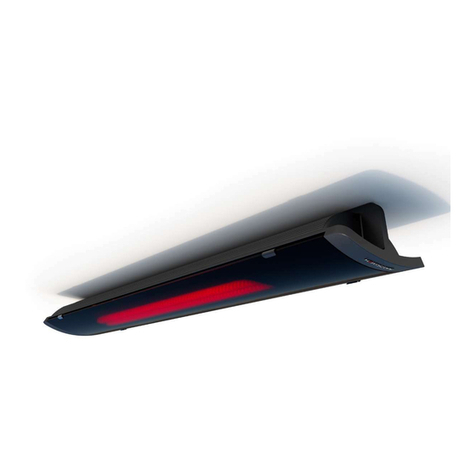
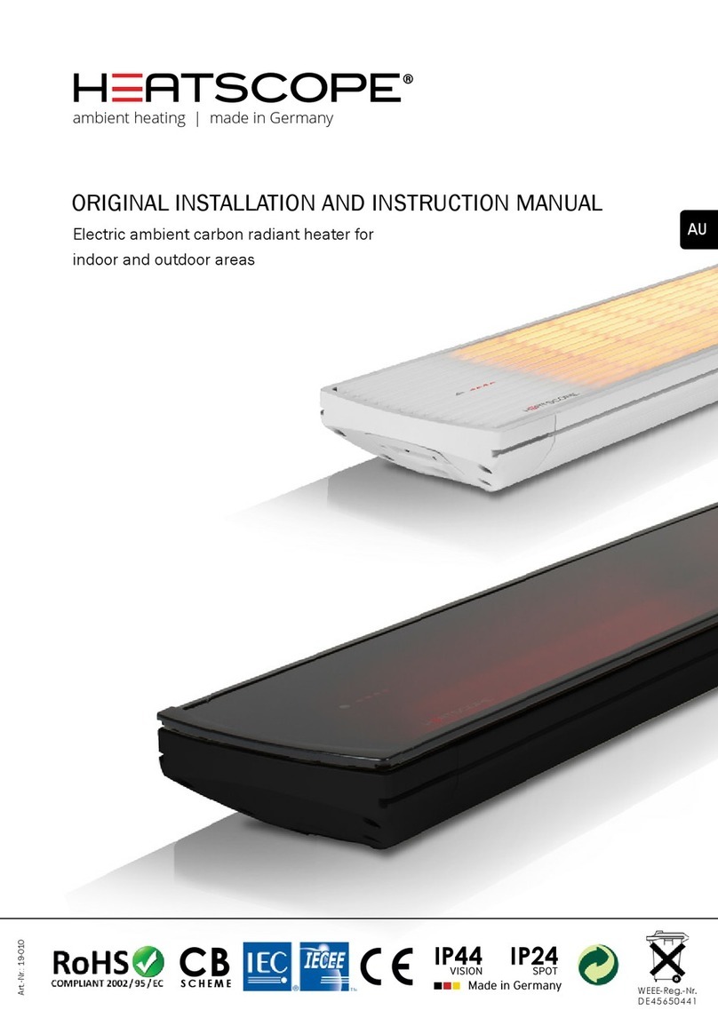
Heatscope SPOT MHS-SM Series User manual

EMC
IP24 E114556
Electrical Safety
ambient heating | made in Germany
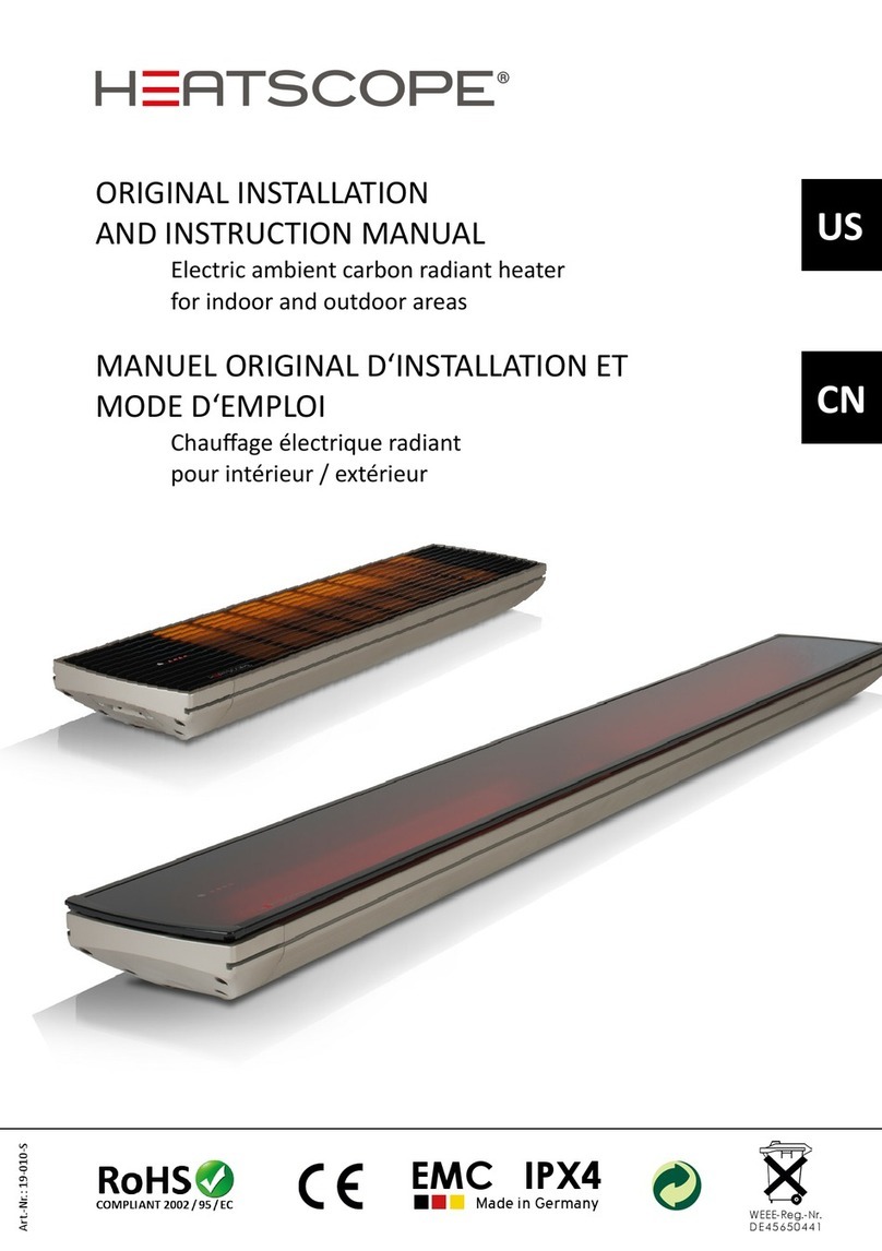
ORIGINAL INSTALLATION AND INSTRUCTION MANUAL
Electric ambient carbon radiant heater for
indoor and outdoor areas
US
developed
designed
made in
Germany
MUNICH HOME SYSTEMS
US
MAD Design USA · 5875 Green Valley Circle, Suite 100 · Culver City / CA 90230 / USA
SAFETY INFORMATION
HEATSCOPE®infrared heaters must be installed and executed only by an authorized expert /
trained professional electrician in accordance with the applicable standards and regulations
for electrical wiring in electrical trade in the respective country / region of installation.


the heater will be used. Route the supply cord and locate the heater so as to be protected
from damage by live stock. Do not use extension cords. Inspect cord before using. Unplug

after winter season.

under any circumstances.
WARNING: This unit is not equipped with an application to regulate the room temperature.
The heater must not be used in small rooms inhabited by people who cannot leave the room


unless they are overseen all the time. Children older than 3 years and younger than 8 years


the unit is installed properly. CAUTION: Some parts of the unit get very hot and may cause

or mental abilities or lack of experience and/or knowledge. are present in the room.




were instructed how to use the unit safely and have received instructions how to operate/
use the unit and which endangerments may result during the use of the unit. Children must
-
less they are supervised by a person responsible for their safety.
The unit must never be used unattended. Children must be supervised at all times to ensure

CAUTION! The device is not intended for use by persons (including children) with reduced

especially from children.
It is NOT ALLOWED to use the heater in hazardous locations listed below; installation in non-
hazardous locations only:

-
MUNICH HOME SYSTEMS AMBIENT HEATING SOLUTIONS
US
Phone: +1 (888) 590 3335 · [email protected] · www.mad-usa.com
ting conditions);
-
pors or liquids are present continuously or for long periods of time under normal operating
conditions);

vapors or liquids are likely to exist under normal operating conditions);

-
tions);
-
le dust can exist all of the time or some of the time under normal operating conditions);
-
le dust are not likely to exist under normal operating conditions);



handled);


operating conditions);




1. Please check that your HEATSCOPE®radiant heater and accessories are complete and not
damaged. In special take care of the glass holders of the model range VISION, which hold
and surround the glass ceramic front screen. Press the holders carefully back in position,
untill they click into place again.
If the housing or reector is deformed/damaged or the heating element is broken, do not use
the HEATSCOPE®unit. Please contact the vendor or the manufacturer.
The cable must not be crushed, squeezed or damaged.
If the unit or accessories show signs of defects, cracking, breakage or other damage or if the
industrial glass ceramics screen is damaged, discontinue use and have them repaired. In this
case, disconnect the unit from the power supply, return it to the manufacturer or dispose of it.
The unit should be labelled accordingly to prevent it being reconnected.
MUNICH HOME SYSTEMS
US
MAD Design USA · 5875 Green Valley Circle, Suite 100 · Culver City / CA 90230 / USA
2. For installation use only the supplied accessories or original accessories approved by the
manufacturer. The power cable or other components of the HEATSCOPE®radiant heater may
only be replaced by a professional servicing company enlisted by the manufacturer. Before st-
arting the installation, you must ensure that the operating voltage corresponds to that stated
on the nameplate of the HEATSCOPE®or accessories. Note that depending on the currently
available supply voltage the actual power of the device may change as well as the emitted
power as a result of environmental inuences.
The supply cable must be connected generally in a commercially available wet room distribu-
tion box with IP65 protection class acc. to IEC or UL / CSA (not within the scope of supply).
3. A short power-supply cord (or short detachable power-supply cord) is provided to reduce
the risks resulting from becoming entangled in or tripping over a larger cord.
Extension cords (or longer detachable power-supply cords) are available and may be used if
care is exercised in their use.
lf an extension cord (or a long detachable power-supply cord) is used:
1) The marked electrical rating of the detachable power-supply cord or extension cord should
be at least as great as the electrical rating of the appliance.
2) lf the appliance is of the grounded type, the extension cord should be a grounding type
3-wire cord.
3) The longer cord should be arranged so that it will not drape over the countertop or tabletop
where it can be tripped over, snagged, or pulled on unintentionally (especially by children).
Outdoor extension cords should be used with outdoor use products and are surface marked
with sufx letter „W“ and with a tag stating „Suitable for Use with Outdoor Appliances“.
CAUTION! To provide continued protection against risk of electric shock, connect to properly
grounded outlets only.
4. HEATSCOPE®heaters together with all available accessories feature IP protection class
IP24. Nevertheless, it is mandatory to install the unit on a surface where it is well protected
from any weather inuences like rain and dust from above; so the HEATSCOPE®has to be
installed under a roof, an overhang or in combionation with the optional available weather
shield. Never install the HEATSCOPE®heater on combustible material like wood, wooden
surfaces etc.
5. CAUTION! To reduce the risk of electric shock, keep extension cord connection dry and off
the ground. As soon as the unit is connected to a power source and switched on using an
„ON/OFF“ switch or other ope rating component, it takes a maximum of 15-30 seconds until it
reaches its operating temperature.
Important! Before rst use, please clean the heater surface with an alcohol-free customary
glass cleaner. Fingerprints can cause discolour at the surface.
6. CAUTION! Hot surface! Avoid contact! Risk of burns! – The front screen (approx. max. 572
°F) and protective n front (approx. max. 752 °F) gets very hot while the unit is operating.
MUNICH HOME SYSTEMS AMBIENT HEATING SOLUTIONS
US
Phone: +1 (888) 590 3335 · [email protected] · www.mad-usa.com
Do not cover either part of the front or the entire front of the radiant heater. Do not touch any
part of the HEATSCOPE® during operation and up to 30 minutes after switching it off.
7. For your own safety, never dry textiles or other materials using the HEATSCOPE®. Covering
the radiant heater may result in a re! Always maintain a distance from the heating surface of
the HEATSCOPE® of at least 60.00 inch from textiles, cloth and other easy inammable soft
materials.
8. Ensure that cables, furniture, ammable materials or other objects do not come into con-
tact with the surface of the radiant heater and never cover the unit. Under no circumstances
should the unit be covered or enclosed with insulating or similar materials. Adequate ventilati-
on surrounding the heater must be ensured at any time. Ledgers, beams and rafters must
not be cut into or grooved to install the infrared heater.
The following spacings are necessary to limit the temperature between the HEATSCOPE®
radiant heater and adjacent surfaces:
Ceiling installation: min. 6.70 inch to the ceiling, min. 79.00 inch to a
horizontal surface, min. 16.00 inch to a vertical surface;
Wall installation: min. 6.00 inch to the ceiling, min. 71.00 inch to a
horizontal surface, min. 16.00 inch to a vertical surface.
When installing the HEATSCOPE®radiant heater, ensure that the safety clearances from the
wall and ceiling set out in this manual are maintained.
Always maintain a distance from the heating surface of the HEATSCOPE® of at least 60.00
inch from textiles, cloth and other easy inammable soft materials.
9. Disconnect the radiant heater from the power supply before cleaning it, adjusting the angle
or removing it from the wall/ceiling. Wait until the heating elements are not glowing any more
and the housing is noticably cooled down. If buried cables are used, switch off the power
using an omnipolar switch.
10. The HEATSCOPE® features an omnipolar „ON/OFF“ switch. The unit can be controlled
manually either using an IR remote control (supplied, depending on the model) or a selector
switch on the unit itself (depending on the model as well). The unit must be connected to
a residual current circuit breaker and a fuse on the installation side – a ground fault circuit
interrupter (GFCI) must be installed.
11. The unit must only be used with an approved isolating system, which must be built in the
existing electrical installation acc. to the facility regulations. The heater comes as standard
with a separate open-ended cable for connection purposes.
12. The power cable or buried cable with omnipolar switch may only be replaced by a pro-
fessional specialist electrical company enlisted or approved by the manufacturer. Heating
elements, other components or parts of the housing may only be replaced by a service orga-
nisation enlisted by the manufacturer.
If you yourself or someone enlisted by you carries out repairs, they will not be covered by
MUNICH HOME SYSTEMS
US
MAD Design USA · 5875 Green Valley Circle, Suite 100 · Culver City / CA 90230 / USA
the guarantee. Improper repairs and incorrect installation or operation shall invalidate the
guarantee immediately.
13. If the heater was installed inappropriately or was connected unhomogeneously with the
local electrical supply cable, high transfer resistances may occur, which lead to overheating of
the device. For the heating system and many custom applications the heaters were equipped
with a NTC temperature control and an additional latching temperature limiter.
Ordinarily possible overhaeting due to inappropriate installation is protected by the NTC
temperature control and the latching temperature limiter. If overheating of a carbon heating
element occur due to interlinkage of mounting and installation mistakes, the carbon la-
ments inside of the quarz tubes will fuse and safely disconnect the current ow. Even after
a mechanical break of the quarz tubes, the carbon heating spirals will not work any longer.
Besides the n front screen of the SPOT heaters and the glass ceramic, high temperature
resistant front screen of the VISION heaters provide best protection of the installed carbon
heating elements.
Functional description of the NTC temperature control: If the system temperature of the
electronical control exceeds 217.4 °F, the upper heating element will shut off temporary by
default to avoid overhaeting of the electronical parts. After a short time the heating element
will switch on automatically again. The self-controlled shut off of the heater will take place
only, if the heat dissipation inside the device is inappropriate, if the heat radiation is inter-
fered or if the ambience temperetaure is way too high. Apart from that the NTC temperature
control supports energy sangs, if the ambient tempe ratures are too high and the highest
heating level of the heating unit is not necessary.
Functional description of the latching temperature limiter: If the NTC temperature control is
not working against expectations, the latching temperature limiter will shut down the lower
heating element permanently, until the heater is shut off totally by hand. After cooling down
(warm to the touch) and xing the inappropriate heat dissipation inside the device and/or the
interferred heat radiation the heater can be switched on again. If the lower heating element
shuts down once more, a system malfunction or a heat dissipation inside the device or an
interference of the heat radiation or an error in the electrical installation may be the reason. If
a system malfunction inside the device causes the shut down, the heater must be repaired by
a professional technician; please contact your dealer immediately. If a wrong cable connec-
tion causes the shut down, this has to be checked and xed through a professional electrician
on the spot.
Installation and connecting regulations with tested and approved luster terminals are part of
the delivered equipment.
14. The radiant heater must not be installed directly below a power source/socket. The sides
of the unit must be at least 8.00 inch from the nearest power source. Sockets/power sources
must be freely accessible at all times and comply with the following specications: 220–240
V AC , 50/60 Hz, 16 A with 16 A fuse. No other loads may be connected to this power source.
15. The radiant heater must not be installed in close vicinity to bathtubes, showers or pools
nor in rooms where there is permanent high humidity. The distance to the bathtub or shower
MUNICH HOME SYSTEMS AMBIENT HEATING SOLUTIONS
US
Phone: +1 (888) 590 3335 · [email protected] · www.mad-usa.com
must be at least 40 inch and the distance to the pool at least 80 inch. A person standing in
the bathtube, shower or pool should never reach the switch or controller of the heater. If the
HEATSCOPE® is installed in such an environment with high humidity, the switches or other
operating components must be positioned in such a way that they cannot be touched by per-
sons who are in direct contact with water. When a radiant heater is installed in a bathroom,
the CE standard requires that at least one heating element visibly „glows“ as soon as the unit
is switched on.
16. CAUTION! To provide continued protection against the risk of electric shock, disconnect
the supply cord before cleaning, adjusting the angle or removing it from the wall/ceiling. Wait
until the heating elements are not glowing any more and the housing is noticably cooled
down. If buried cables are used, switch off the power using an omnipolar switch. Wait at least
30 minutes after the last use before you start cleaning it. All surfaces should be cleaned
using a damp cloth only. Never use cleaning products containing alkaline substances such as
sodium hydroxide or soap, surfactants or solvents such as alcohol. Use only a very soft cloth
or a brush for the reector and the heating elements.
Do not clean this product with a water spray or the like.
17. Make absolutely sure to always switch off the device after use.
18. Store product indoors when not in use – out of the reach of children.
MUNICH HOME SYSTEMS
US
MAD Design USA · 5875 Green Valley Circle, Suite 100 · Culver City / CA 90230 / USA
CEILING INSTALLATION
2 x2 x 2 x 4 x
1 x
 
3.
2 x
2 x 4 x2 x
A (inch) B (inch)
 ≤ 9.45 ≥ 5.35
 ≤ 11.85 ≥ 6.90
 ≤ 14.60 ≥ 6.90

 
A (inch) B (inch)
 ≤ 11.85 ≥ 6.90
 ≤ 25.60 ≥ 6.90
 ≤ 45.30 ≥ 6.90
MUNICH HOME SYSTEMS AMBIENT HEATING SOLUTIONS
US
Phone: +1 (888) 590 3335 · [email protected] · www.mad-usa.com
WALL MOUNTING
 
3.
2 x
1 x
2 x 2 x 4 x2 x 2 x 4 x 4 x2 x

 

 

 
MUNICH HOME SYSTEMS
US
MAD Design USA · 5875 Green Valley Circle, Suite 100 · Culver City / CA 90230 / USA
MUNICH HOME SYSTEMS AMBIENT HEATING SOLUTIONS
US
Phone: +1 (888) 590 3335 · [email protected] · www.mad-usa.com

N

O
I
HEATSCOPE®SP
MHS-SP1600AB.250
MHS-SP1600BK.250
MHS-SP1600WT.250
110-120 V AC
50/60 Hz


Circuit breaker / fuse switch
on the installation side
INPUT
PE
PE
MUNICH HOME SYSTEMS
US
MAD Design USA · 5875 Green Valley Circle, Suite 100 · Culver City / CA 90230 / USA

O
I
HEATSCOPE®SP // HEATSCOPE®VT
MHS-SP2200AB.200, MHS-SP2800AB.200,
MHS-SP2200BK.200, MHS-SP2800BK.200,
MHS-SP2200WT.200, MHS-SP2800WT.200
MHS-VT1600AB.200, MHS-VT2200AB.200, MHS-VT3200AB.200,
MHS-VT1600BK.200, MHS-VT2200BK.200, MHS-VT3200BK.200,
MHS-VT1600WT.200, MHS-VT2200WT.200, MHS-VT3200WT.200
220-240 V AC
50/60 Hz


The supply cable must be connected gene-
rally in a commercially available wet room
distribution box with IP65 protection class
acc. to IEC or UL / CSA (not within the scope
of supply).
PE
N

INPUT
PE
Circuit breaker / fuse switch
on the installation side
MUNICH HOME SYSTEMS AMBIENT HEATING SOLUTIONS
US
Phone: +1 (888) 590 3335 · [email protected] · www.mad-usa.com


MHS-SM1600AB.200, MHS-SM2200AB.200, MHS-SM2800AB.200,
MHS-SM1600BK.200, MHS-SM2200BK.200, MHS-SM2800BK.200,
MHS-SM1600WT.200, MHS-SM2200WT.200, MHS-SM2800WT.200
MHS-VE1600AB.200, MHS-VE2200AB.200, MHS-VE3200AB.200,
MHS-VE1600BK.200, MHS-VE2200BK.200, MHS-VE3200BK.200,
MHS-VE1600WT.200, MHS-VE2200WT.200, MHS-VE3200WT.200
O
I
III
HEATSCOPE®SP // HEATSCOPE®VT
220-240 V AC
50/60 Hz

A: 50%
B: 50%
The supply cable must be connected gene-
rally in a commercially available wet room
distribution box with IP65 protection class
acc. to IEC or UL / CSA (not within the scope
of supply).
PE


INPUT
PE
Circuit breaker / fuse switch
on the installation side
MUNICH HOME SYSTEMS
US
MAD Design USA · 5875 Green Valley Circle, Suite 100 · Culver City / CA 90230 / USA
MANUAL CONTROL
MHS-SM1600, MHS-SM2200, MHS-SM2800
MHS-VE1600, MHS-VE2200, MHS-VE3200
O
I
III
LED:
O
I
III
O
I
IIIIII

50 %
0 %
O
I
III
0 %
O
I
MUNICH HOME SYSTEMS AMBIENT HEATING SOLUTIONS
US
Phone: +1 (888) 590 3335 · [email protected] · www.mad-usa.com
IR REMOTE CONTROL
MHS-SP1600, MHS-SP2200, MHS-SP2800
MHS-VT1600, MHS-VT2200, MHS-VT3200
ON
/ OFF
+ 1
– 1




AMBIENT HEATING
LED: O
I
O
I
O
I
0 %
0 %



O
I


50 %



O
I
O
I


0 %
0 %
MUNICH HOME SYSTEMS
US
MAD Design USA · 5875 Green Valley Circle, Suite 100 · Culver City / CA 90230 / USA
Minimum distances wall mounting
The following installation regulations ensure that the HEATSCOPE®ambient heater is working effectively.
All minimum clearances that must be met regardless of the installation environment are listed.



> 71.00 inch
> 6.00 inch
< 16.00 inch
> 71.00 inch
> 71.00 inch
> 6.00 inch
> 60.00 inch
> 16.00 inch
> 60.00 inch
MUNICH HOME SYSTEMS AMBIENT HEATING SOLUTIONS
US
Phone: +1 (888) 590 3335 · [email protected] · www.mad-usa.com
X X
X
The clearances given are minimum values and may differ from the local building and re regulations.
The latter must be observed and complied with in any case.
MUNICH HOME SYSTEMS
US
MAD Design USA · 5875 Green Valley Circle, Suite 100 · Culver City / CA 90230 / USA



> 79.00 inch
> 6.70 inch
> 16.00 inch
> 79.00 inch
> 79.00 inch
> 6.00 inch
> 60.00 inch
> 6.70 inch
> 4.00 inch
> 16.00 inch
Minimum distances wall mounting
The following installation regulations ensure that the HEATSCOPE®ambient heater is working effectively.
All minimum clearances that must be met regardless of the installation environment are listed.
MUNICH HOME SYSTEMS AMBIENT HEATING SOLUTIONS
US
Phone: +1 (888) 590 3335 · [email protected] · www.mad-usa.com
X X
X
The clearances given are minimum values and may differ from the local building and re regulations.
The latter must be observed and complied with in any case.
MUNICH HOME SYSTEMS
US
MAD Design USA · 5875 Green Valley Circle, Suite 100 · Culver City / CA 90230 / USA

> 71.00 inch
> 10.00 inch
> 60.00 inch
X
X
Minimum distances wall mounting
The following installation regulations ensure that the HEATSCOPE®ambient heater is working effectively.
All minimum clearances that must be met regardless of the installation environment are listed.

This manual suits for next models

39

Other Heatscope Electric Heater manuals

Heatscope MHS-SM1600 User manual

Heatscope

Heatscope MHS-SM1600 User manual

Heatscope MHS-SM1600 Quick guide

Heatscope

Heatscope MHS-SM1600 Quick guide

Heatscope PURE User manual

Heatscope

Heatscope PURE User manual

Heatscope PURE Quick guide

Heatscope

Heatscope PURE Quick guide

Heatscope MHS-SM1600 User manual

Heatscope

Heatscope MHS-SM1600 User manual

Heatscope MHS-VT1600WT.100 Quick guide

Heatscope

Heatscope MHS-VT1600WT.100 Quick guide

Heatscope SMARTBOX User manual

Heatscope

Heatscope SMARTBOX User manual

Heatscope PURE User manual

Heatscope

Heatscope PURE User manual

Heatscope ZERO User manual

Heatscope

Heatscope ZERO User manual

Heatscope PURE User manual

Heatscope

Heatscope PURE User manual

Heatscope Spot User manual

Heatscope

Heatscope Spot User manual

Heatscope MHS-600 User manual

Heatscope

Heatscope MHS-600 User manual

Heatscope MHS-SM1600BK.100 User manual

Heatscope

Heatscope MHS-SM1600BK.100 User manual

Heatscope MHS-SM1600 User manual

Heatscope

Heatscope MHS-SM1600 User manual

Heatscope FREE Quick guide

Heatscope

Heatscope FREE Quick guide

Heatscope MHS-SM1600 User manual

Heatscope

Heatscope MHS-SM1600 User manual

Heatscope MHS-PE3000 User manual

Heatscope

Heatscope MHS-PE3000 User manual

Heatscope MHS-SM1600BK.100 User manual

Heatscope

Heatscope MHS-SM1600BK.100 User manual

Popular Electric Heater manuals by other brands

Elnur ECOHHR 20 Guide

Elnur

Elnur ECOHHR 20 Guide

Trotec IR 2000 S operating manual

Trotec

Trotec IR 2000 S operating manual

Slant/Fin VICTORY II VHS Series Specifications

Slant/Fin

Slant/Fin VICTORY II VHS Series Specifications

Chromalox PE417-3 Installation, operation and renewal parts identification

Chromalox

Chromalox PE417-3 Installation, operation and renewal parts identification

Dyna-Glo EG5000DGP Installation & maintenance instructions

Dyna-Glo

Dyna-Glo EG5000DGP Installation & maintenance instructions

TESY FinEco quick start

TESY

TESY FinEco quick start

Intertec Data Systems CP MEGATHERM DN.A HI operating instructions

Intertec Data Systems

Intertec Data Systems CP MEGATHERM DN.A HI operating instructions

Draper ESH2000PTC user manual

Draper

Draper ESH2000PTC user manual

Clarke Devil 330 Operating & maintenance instructions

Clarke

Clarke Devil 330 Operating & maintenance instructions

Rointe Napoli AQUA TNAA 70A100 Series instruction & installation guide

Rointe

Rointe Napoli AQUA TNAA 70A100 Series instruction & installation guide

Stanley ST-302-231-E instruction manual

Stanley

Stanley ST-302-231-E instruction manual

Harvia TRC70 Assembly, installation and maintenance instructions

Harvia

Harvia TRC70 Assembly, installation and maintenance instructions

EUROM ALUTHERM 1000 Instruction booklet

EUROM

EUROM ALUTHERM 1000 Instruction booklet

Holmes HFH103 owner's guide

Holmes

Holmes HFH103 owner's guide

Comfort Glow QDE1350 owner's manual

Comfort Glow

Comfort Glow QDE1350 owner's manual

EUROM EK1999 operating instructions

EUROM

EUROM EK1999 operating instructions

DELTACALOR PAPILLON 1 Operation and installation manual

DELTACALOR

DELTACALOR PAPILLON 1 Operation and installation manual

Electrolux ECH/AT-2000 3AI-W EEC user manual

Electrolux

Electrolux ECH/AT-2000 3AI-W EEC user manual

manuals.online logo
manuals.online logoBrands
  • About & Mission
  • Contact us
  • Privacy Policy
  • Terms and Conditions

Copyright 2025 Manuals.Online. All Rights Reserved.