Product Information KCI 1319, KBI 1335 11/2021 Product Information KCI 1319, KBI 1335 11/2021
6 7
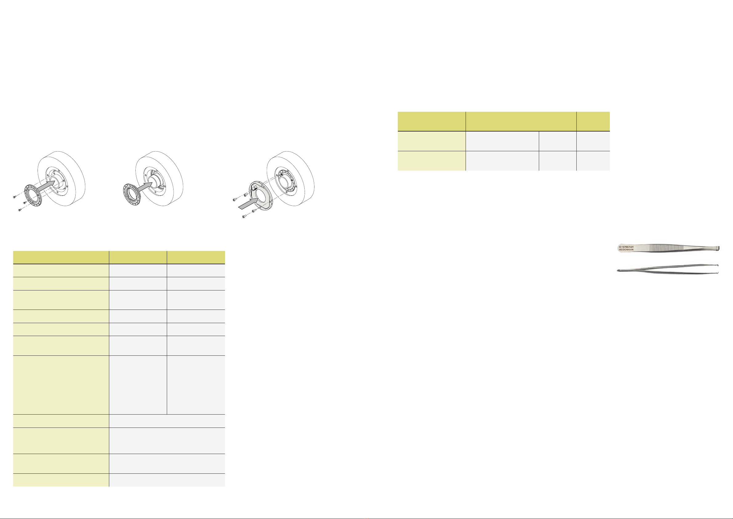
The KCI 1319/KBI 1335 is mounted either
via screw-fastening of the circular scale
or through press-fitting of the disk/hub
assembly and mounting of the scanning
unit. The disk/hub assembly is thereby
either press-fitted onto the shaft, or the
circular scale is screw-fastened to the
given shaft with three screws. The
scanning unit is aligned and mounted via
four holes on the customer’s mounting
surface.
The following material properties and conditions must be complied with for the
customer-side mounting design:
Mating stator Mating shaft
Material Aluminum Steel
Tensile strength Rm≥220 N/mm2≥600 N/mm2
Yield strength Rp0.2 or
yield point Re
–≥400 N/mm2
Shear strength τm130 N/mm2≥390 N/mm2
Interface pressure PG≥250 N/mm2≥660 N/mm2
Modulus of elasticity E
(at 20 °C)
70 kN/mm2to
75 kN/mm2
200 kN/mm2to
215 kN/mm2
Coefficient of thermal expansion therm
(at 20 °C)
≤25 · 10–6 K–1 Screw-fastened
version:
10 · 10–6K–1 to
17 · 10–6K–1
Press-fitted version:
10 · 10–6K–1 to
12 · 10–6K–1
Surface roughness RZ≤16 µm
Friction values Mounting surfaces must be clean and free of
grease. Use screws and washers from
HEIDENHAIN in their condition as delivered.
Tightening procedure Use a signal-emitting torque wrench as per
DIN EN ISO 6789, with an accuracy of ±6 %
Mounting temperature 15 °C to 35 °C
Mounting
KCI 1319
KBI 1335
Screws Quantity
Screw for fastening the
scanning unit
ISO 4762-M3×10-8.8-MKL1) ID 202264-87 10 or 100
Fastening screw for
circular scale
ISO 14581-M2×6-A2-702) – –
1) With coating for material bonding anti-rotation lock (for information on use, see the
Encoders for Servo Drives brochure)
2) Without anti-rotation lock; use at least a medium-strength material bonding anti-rotation
lock
Mounting accessories
Screws
Screws (fastening screws) are not included in delivery; the M3x10 screw with material
bonding anti-rotation lock can be ordered separately.
Mounting aid
To avoid damage to the cable, use the mounting aid to connect and disconnect the cable
assembly. Apply pulling force only to the connector of the cable assembly and not to the
wires.
ID 1075573-01
For more mounting information and mounting aids, see the Mounting Instructions
and the Encoders for Servo Drives brochure.The mounting quality can be inspected
with the PWM 21 and the ATS software (see Document 1082415).
The press-fitting process may be performed
only once for each disk/hub assembly. For
the press-fit, comply with the material
properties and conditions for the mating
surface stated for proper use in the relevant
documents. These requirements must be
followed, even when new disk/hub
assemblies are press-fitted onto customer
shafts that have already been used. Once
the lower limit of the press-fit force has
been exceeded, the press-fit force being
applied must remain within the specified
range for the rest of the procedure until the
end position is reached.