2. Safety
Authorised persons
The encoder should only be assembled and dismantled by a qualified
electrician, as the unit contains sensitive electronic circuits.
Risk of injury due to rotating shafts
Hair and items of clothing may become caught up in rotating shafts.
Prior to commencing all works, disconnect all power supplies and
ensure that the working environment is Safe!
Risk of destruction due to static electricity
The MOS modules contained in the encoder are very sensitive to high
voltages such as can arise due to friction of the clothing.
Do not touch plug contacts or electronic components!
Risk of destruction due to mechanical overload
Rigid mounting will give rise to constraining forces which will permanently
overload the bearings.
Never restrict the freedom of movement of the encoder! Use only the
enclosed sheet steel springs or a suitable coupling to secure the unit!
Risk of destruction due to mechanical shock
Violent shocks, e.g. due to hammer blows, can lead to the destruction of the
optical sensing system and the ball bearings.
Never use force! Assembly is simple provided that correct procedure is
followed.
Risk of destruction due to overloading
The unit may only be operated within the limits specified in the technical
data.
Fields of application: industrial processes and controls.
Over voltage at the connecting terminals must be limited to over voltage-
class-II values (SELV).
The connecting cable is not for dragline mounting, only for fix mounting.
This encoder is a supply part destined for mounting to an appliance (motor,
machine). It is not provided for customer sale.
Manufacturers integrating this encoder to their facilities are responsible as
well for compliance with E guidelines as for the E mark.
2. Sicherheitshinweise
Befugte ersonen
Der Drehgeber darf nur von einer Elektrofachkraft montiert und demontiert
werden, da im Drehgeber empfindliche elektronische Schaltkreise enthalten
sind.
Verletzungsgefahr durch rotierende Wellen
Haare und Kleidungsstücke können von rotierenden Wellen erfasst werden.
Vor allen Arbeiten alle Betriebsspannungen ausschalten und Arbeits-
umgebung sichern!
Zerstörungsgefahr durch Körperelektrizität
Die MOS-Bausteine im Drehgeber sind sehr empfindlich gegen hohe
Spannungen, wie sie z. B. durch die Reibung der Kleidung entstehen
können.
Steck-Kontakte und elektronische Komponenten nicht berühren!
Zerstörungsgefahr durch mechanische Überlastung
Eine starre Befestigung führt zu dauerhafter Überlastung der Lager durch
Zwangskräfte.
Die Beweglichkeit der Geberwelle niemals einschränken! Zur Befesti-
gung nur die beigelegten Federbleche oder eine geeignete Kupplung
verwenden!
Zerstörungsgefahr durch mechanischen Schock
Starke Erschütterungen, z. B. Hammerschläge, können zur Zerstörung der
optischen Abtastung und der Kugellager führen.
Niemals Gewalt anwenden! Bei sachgemäßer Montage lässt sich alles
leichtgängig zusammenfügen.
Zerstörungsgefahr durch Überlastung
Das Gerät darf nur innerhalb der Grenzen betrieben werden, wie sie in
den technischen Daten vorgegeben sind.
Anwendungsbereich: Industrielle rozesse und Steuerungen.
Überspannungen an den Anschlussklemmen müssen auf Werte der
Überspannungskategorie II begrenzt werden (SELV).
Das Anschlusskabel ist nicht schleppfähig und nur für feste Verlegung
geeignet.
Dieser Geber ist ein Zulieferteil, das für den Einbau in ein Gerät (Motor,
Maschine) vorgesehen ist. Er ist nicht für den Verkauf an den Endkun-
den bestimmt.
Der Hersteller, der diesen Geber in sein Gerät integriert, ist verantwort-
lich für die Einhaltung der E-Richtlinien und die E-Kennzeichnung.
1. Vorwort
Dieses Anleitung soll Ihnen den Anschluss und die Inbetriebnahme
des Drehgebers ermöglichen.
Weitere Informationen finden Sie im Drehgeberkatalog bzw. erhalten
Sie auf Anfrage oder per Download von unserer Internetseite.
www.hengstler.de
1. reface
These installation instruductions are provided for the connection and
starting procedure of your shaft encoder.
You will get further information from the Acuro datasheet, on request
or on download from our Internet site.
www.hengstler.com
1. Avant-propos
es instructions ont pour but de vous permettre la mise en route du
capteur angulaire.
Vous trouverez de plus amples informations dans le fiche technique
ou sur simple demande ou par téléchargement à partir de notre site
Internet.
www.hengstler.com
1. Introduzione
Questo manuale dínstallazione ha il compito di darle la possibilità di
allaciare e mettere in funzione i trasduttori.
Ulteriori informazioni riceve del folgio caratteristiche o a richiesta o
servitevi die download nel nostro sito internet.
www.hengstler.com
1. réambulo
Este manual de instalación le permite la conexión y puest en marcha
de los transmisores giratorios.
Encontrará mayor información en el hoja de especificaciones o
obtenerá esta en ruego, o bien, solicítela directamente a nuestra
empresa.
www.hengstler.com
Inkrementeller Drehgeber
RI 58-F
Installationsanleitung
Incremental Shaft Encoders
RI 58-F
Installation instructions
Codeur incrémental
RI 58-F
Instructions d´installation
Trasduttori incrementali
RI 58-F
Istruzioni di installazione
Transmisores giratorios incrementales
RI 58-F
Instrucciones de instalación
Art. No.: 2 531 261
Edition.: 3 270710 TK
2. Sécurité
ersonnel autorisé
Du fait que le codeur renferme des circuits électroniques sensibles, seul le
personnel compétent est autorisé à monter ou démonter le codeur.
Mise en garde contre les arbres en rotation
Les cheveux et les vêtements peuvent être happés par les arbres en
rotation.
Prière de sécuriser I'environnement de travail avant de mettre les
machines en service.
Risque de destruction par des décharges électrostatiques
Les composants MOS contenus dans le codeur sont très sensibles aux
décharges électrostatiques provoquées par exemple par le frottement de
certains vêtements.
Ne pas toucher aux contacts enfichables ni aux composants électroni-
ques.
Risque de destruction par des surcharges mécaniques
Une fixation rigide conduit à une contrainte permanente sur les paliers due
aux forces de réaction.
Ne jamais entraver le mouvement de l’arbre du codeur. Pour la fixation,
utiliser uniquement les tôles élastiques à ressorts livrées avec le codeur
ou un accouplement adéquat.
Risque de destruction par des chocs mécaniques
De fortes vibrations ou des chocs, par ex. des coups de marteau, peuvent
provoquer la destruction du système optique de balayage du codeur et des
roulements à billes.
Ne jamais forcer. Un montage correct permet un assemblage facile des
éléments.
Risque de destruction par surcharge
Mettre l’appareil en œuvre uniquement dans les limites prescrites sur
les notices techniques.
Domaine d'application : commandes et processus industriels.
Les surtensions sur les bornes de raccordement doivent êtres limitées aux
valeurs de la catégorie II concernant les surtensions (SELV).
e codeur correspond à une fourniture prévue pour être intégrée dans un
appareil (moteur, partie mécanique). II n'est pas destiné à la vente directe
au client final.
Le constructeur intégrant ce codeur dans son équipement est tenu de
respecter les directives E ainsi que le marquage E.
2. Seguridad
ersona autorizada
Dado que el codificador rotatorio contiene circuitos electrónicos sensibles,
únicamente un electricista especializado está autorizado a montarlo y a
desmontarlo.
eligro de lesión mediante ejes en rotación
Los cabellos y las prendas de vestir pueden ser arrastrados por los ejes en
rotación.
¡Antes de comenzar cualquier trabajo, desconecte todas las tensiones
de alimentación y asegúre el entorno de trabajo!
eligro de destrucción por electricidad electrostática
Los componentes de MOS del codificador rotatorio son muy sensibles a
las altas tensiones, que se producen p.ej. por el frotamiento de la ropa.
¡No toque los contactos enchufables y componentes electrónicos!
eligro de destrucción por sobrecarga mecánica
Un soporte rígido produce una sobrecarga permanente de los cojinetes
ocasionada por las fuerzas de ligadura.
¡No limite nunca la libertad de movimiento del eje del codificador! ¡Para
fijarlo, utilice únicamente las chapas elásticas adjuntadas o un
dispositivo de acoplamiento adecuado!
eligro de destrucción por choque mecánico
Las vibraciones fuertes, p.ej. las que se producen por los golpes de un
martillo, pueden destruir el dispositivo de exploración óptica y los
rodamientos de bolas.
¡No recurra nunca a la violencia! El montaje es sencillo, siempre y
cuando se sigan los pasos correctos.
eligro de destrucción por sobrecarga
No está permitido utilizar el aparato fuera de los límites prescritos en la
hoja de datos técnicos.
Campo de aplicación: rocesos industriales y unidades de mando.
Es imprescindible limitar las sobretensiones en los bornes de conexión a
los valores correspondientes a la categoría de sobretensión II (SELV).
Este codificador forma parte del suministro y está destinado a la instalación
en un aparato (motor, máquina). No está previsto para la venta al cliente.
Todo fabricante, que integre este codificador en uno de sus aparatos, se
responsabiliza por el cumplimiento de la normativa E y de la marca E.
2. Avvertenze sulla Sicurezza
ersone autorizzate
Il trasduttore di rotazione può essere montato e smontato solo da un
elettricista specializzato, poiché il trasduttore di rotazione è dotato di circuiti
elettronici sensibili.
ericolo di lesioni dovute ad alberi in rotazione
I capelli e gli indumenti possono impigliarsi negli alberi in rotazione.
Prima di eseguire qualsiasi lavoro disinserire tutte le tensioni d’esercizio
e proteggere la zona di lavoro!
ericolo di distruzione dovuta all'elettricità formatasi nel corpo
I componenti MOS del trasduttore di rotazione sono molto sensibili alle
alte tensioni come quelle che possono formarsi in seguito allo strofinio degli
indumenti.
Non toccare i connettori a spina ed i componenti elettronici!
ericolo di distruzione dovuta a sovraccarico meccanico
Un fissaggio troppo rigido provoca un sovraccarico permanente dei
cuscinetti per via delle forze ad azione forzata.
Non limitare mai la mobilità dell’albero del trasduttore! Per il fissaggio
utilizzare solo le lamiere elastiche in dotazione oppure un giunto
adeguato!
ericolo di distruzione dovuta a shock meccanico
Forti urti, ad esempio i colpi di martello, possono causare la distruzione del
sistema di scansione ottica e dei cuscinetti a sfera.
Non usare violenza! Lavorando appropriatamente si può unire tutto più
leggermente.
Pericolo di distruzione dovuta a sovraccarico.
Fare funzionare l’apparecchio entro i limiti che sono stati specificati nelle
caratteristiche tecniche
Campo d'impiego: processi industriali e dispositivi di comando.
Le sovratensioni sui morsetti devono essere limitate ai valori della categoria
di sovratensione II (SELV).
Questo trasduttore è un elemento complementare destinato al montaggio in
un apparecchio (motore,macchina), e non può essere venduto al cliente
finale.
Il produttore che incorpora questo trasduttore nel suo apparecchio è tenuto
a far rispettare le direttive E e a farlo contrassegnare col marchio E.
Hotline
+49 (0) 74 24 / 89 - 539
HENGSTLER GmbH
Uhlandstr. 49
D-78554 Aldingen
http://www.hengstler.de
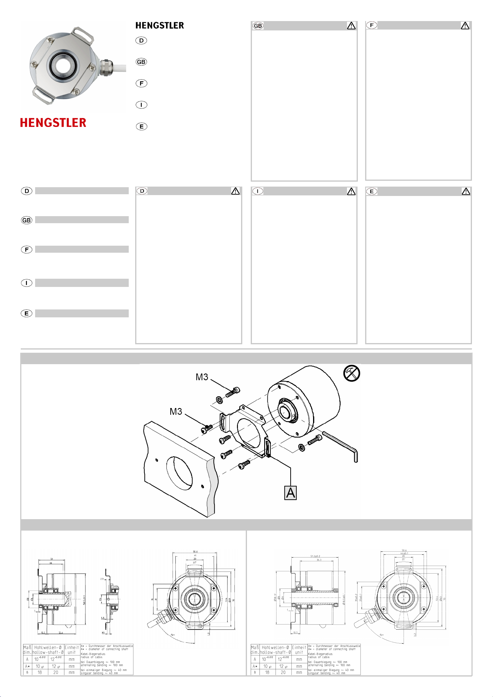
3. Montage
Assembly
Montage
Montaggio
Montaje
4. Maßzeichnung
Dimensioned Drawings
Schema d‘encombrement
Dimensioni
lano acotado
( A ) Federblech
Spring plate
Tôle élastique à ressorts
Lamiera elastica
Chapa para láminas de
Einseitig offene Hohlwelle (Typ ”F“; Klemmring vorne)
Hub shaft (Type ”F“; Clamping ring ahead)
Durchgehende Hohlwelle (Typ ”B“; Klemmring vorne oder hinten)
Through hollow shaft (Type ”B“; Clamping ring ahead or rear)
øA > 10 mm øA ≤10 mm
Maße in mm/ Dimensions in mm Maße in mm/ Dimensions in mm
Md = 0,6
±
0,1 Nm


