Safety and Operating Instructions
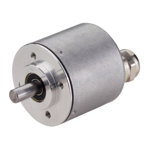
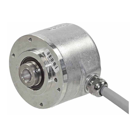
• The absolute shaft encoders of the type RA 58-P/RA 59-P model series are
quality products manufactured in accordance with established electrical
engineering standards.
The units have been delivered from the factory in perfect conformance to
safety regulations.
To maintain this condition and to ensure trouble-free operation, please ob-
serve the technical specifications of this document.
• Installation and mounting may only be performed by an electrotechnical
expert!
• The units may only be operated within the limits specified by the technical
data.
•Maximum operating voltages must not be exceeded!
The units are designed complying with DIN EN 61010-part 1, protection class III.
To prevent dangerous structure-borne currents, the equipment has to be run
on safety extra-low voltage (SELV) and must be in an area of equipotential
bonding.
Please use an external fuse for protection (see Electrical Data).
• Fields of application: industrial processes and controls.
Overvoltage at the connecting terminals must be limited to overvoltage-
class-II values.
• Please avoid shocks to the housing – especially to the encoder shaft – and
axial or radial overload to the encoder shaft.
• Maximum accuracy and durability of our shaft encoders are only granted
when using suitable couplings.
• The high-quality EMC-specifications are only valid together with standard-
type cables and plugs. When using screened cables, the screen must broadly
be connected with ground on both ends. Likewise, the voltage-supply cables
should entirely be screened. If this is not possible you will have to take
appropriate filtering measures.
• Installation environment and wiring are influential on the encoder's EMC:
Thus the installer must secure EMC of the whole facility (device).
• In electrostaticly threatened areas please take care for neat ESD-protection
of plug and connecting cable during installation work.
• Specified maximum shaft loads are only given under restrictions:
– Full bearing life of 1 x 10¹⁰ revolutions (typ.) will be reached at 35% of
full rated shaft load
– a bearing life of 1 x 10⁸revolutions (typ.) will be reached at 100% of full
rated shaft load.
Installation instructions
Absolute Shaft Encoders RA 58-P/RA 59-P,
Interbus (K3)
Item No. 2 543 043 Edition: 25.02.99
Hengstler GmbH
Postfach 11 51 Tel. 07424 – 890
D-78550 Aldingen Fax 07424 – 89370
Introduction
These installation instructions are provided for the connection and starting
procedure of your shaft encoder.
For further informations see user guide:
•RA 58-P/RA 59-P with Interbus (K3): Item No. 2 543 003
General aspects
The shaft encoder of the type RA 58-P/RA 59-P can be programmed via the
Interbus. Due to this function the encoder may be used universally; thus the
range of variants as well as the storage will be reduced for the customer.
A lot of calculating time and expense on the host system will be saved by
data processing within the encoder.
The RA 58-P/RA 59-P is equipped with an EEPROM for remanent storage of
the parameters. When the device is turned on the parameters are transferred
automatically to the memory.
This sign marks paragraphs particularly to be observed to assure
proper use and to avoid risks.
Mechanical data
Shaft diameter 6 mm (synchro flange) / 10 mm (clamping flange)
Max. shaft load ∅6 mm: axial 60 N (13 lbs), radial 110 N (24 lbs)
∅ 10 mm: axial 107 N (24 lbs), radial 160 N (35 lbs)
Speed 10000 RPM (short term), 6000 RPM (continuous duty)
Torque ≤ 0.5 Ncm
Moment of inertia synchro flange approx. 14 gcm2,
clamping flange approx. 20 gcm2
Protection class (EN 60529) housing IP 65*, bearing IP64*
Operating temperature –10 … +60 °C
Storage temperature –25 … +85 °C
Vibration performance (IEC 68-2-6) 100 m/s2(10 … 500 Hz)
Shock resistance (IEC 68-2-27) 1000 m/s2(6 ms)
Types of connection cable axial/radial, connector axial/radial,
connector 2-fold radial, bus terminal box
Housing aluminium
Flange S = synchro flange**, K = clamping flange***
Weight 350 g approx.
Bearing life 1 x 10¹⁰ revolutions (typ.) at 35 % of full rated shaft load
1 x 10⁹revolutions (typ.) at 75 % of full rated shaft load
1 x 10⁸revolutions (typ.) at 100 % of full rated shaft load
* IP 67 for singleturn versions on request
** Mounting with screws M4 *** Mounting with screws M3 or M4
General design as per EN 61010-part 1, protection class III,
contamination level 2, overvoltage class II
Supply voltage1) 10 ... 30 VDC (SELV) with pole protection
Power consumption max. 0.2 A
Recommended external fuse T 0.25 A
Max. current for througoing max. 4.5 A (connector 2-fold),
voltage supply; max. 2 A (bus terminal box);
recommended external fuse T 4.5 A (connector 2-fold), T 2 A (bus terminal box)
EMC Noise emission as per EN 50081-2,
noise immunity as per EN 50082-2
Linearity ± ½ LSB
Type of code Binary
Interface RS 485 for installation remote bus
Protocol Interbus with ENCOM profile K3 (can be parameterised)
Signal lines 5 V difference signals, with potential-free
power supply
Baud rate 500 KB
Update every 600 µs
Physical resolution2) 1024 increments (10 Bit)
4096 increments (12 Bit)
1024 increments/4096 revolutions (22 Bit)
4096 increments/4096 revolutions (24 Bit)
Programmable functions Code sequence, scaling factor, preset, offset
Max. cable length 50 m
1) Real code-disc resolution; in addition, the desired resolution can be reduced by programming
of the encoder parameters
2) Power unit within encoder: potential-free DC/DC converter, 500 V AC withstand voltage between
mains input and electronics
Electrical data
Function (programming directly Preset values Customer-specific
by bus, using configuration- (manufacturer’s parameters
parameter transfer) standard settings)
Code sequence for clockwise rotation ascending
Offset (CP-No. 05) 0
Preset value (CP-No. 04) 0
Scaling factor (CP-No. 08) 1*
* maximal resolution
Programmable functions
Item No. 2 543 043, Edition: 25.02.99
Subject to technical modifications and improvements serving the progress of our devices.

