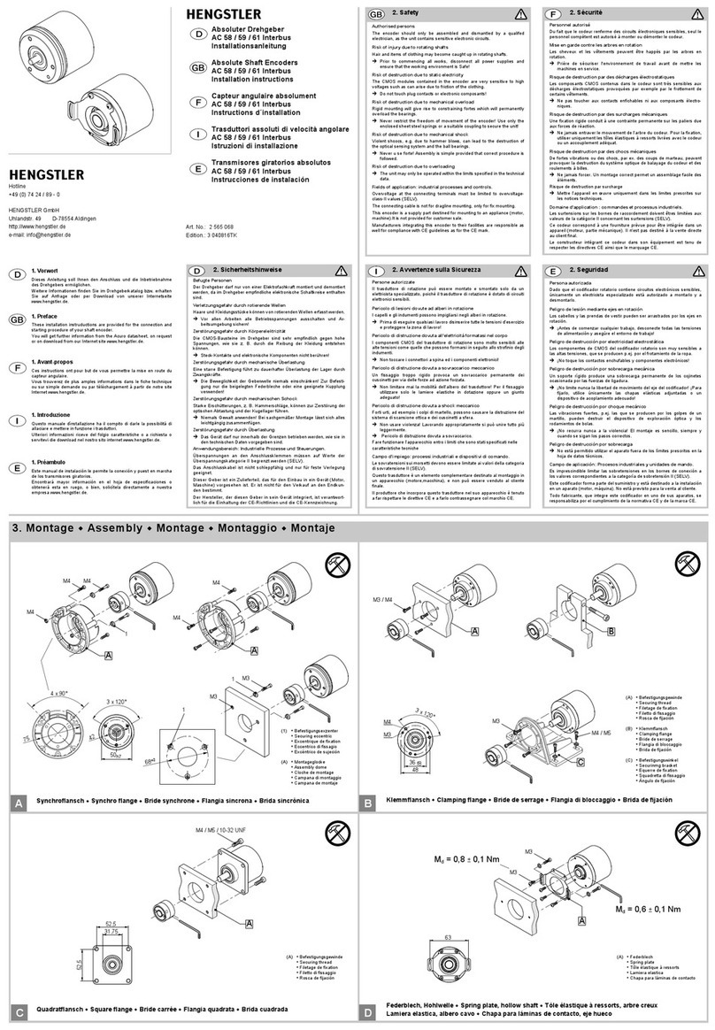
Mechanical installation
General information
Safety instructions
• All installation work must be carried out according to applicable safety
instructions!
• During installation work all appliances worked on must be disconnected
from electric current!
Ensure that these appliances cannot be powered up during the installation
work!
• In order to compensate for axial or radial angular offset of the actuating
shaft, flange and case of the shaft encoder must remain movable!
The shaft encoder case must not rotate:
Fix the flange by means of
– a stator coupling (e.g. spring steel plate) (Accessories: Ord. code 1 531 162)
– or a cylindrical pin. A torque spring (at the encoder flange) in conjunctions
with a cylindrical pin (at the actuating device) provides for the transmission
of torque between encoder and actuating device.
Installation instructions
Incremental Hollow Shaft Encoder RI 58-D, RI 58TD
Page 2/2
Checking the clamping device (D, F, and H versions)
The clamping device of versions D, F, and H contains a clamping ring with a
hexagon-socket screw.
Versions D and F: Clamping ring and torque spring are located on the front
side of the shaft encoder. This side will later on point to the actuator.
With version H, the clamping ring is located in the back, the torque spring is
in front.
The front side will later on point to the actuator.
Check first whether the clamping ring is open:
• Hold the encoder in such a position that you can see the clamping ring from
the side: The hexagon-socket screw is inserted into the side of the clamping
ring.
• Check whether the clamping device of the hollow shaft is released by insert-
ing the actuating shaft into the hollow shaft.
The shaft must slide into the hollow shaft smoothly!
Do not use force and do not try to drive the shaft into the hollow with
hammer blows!
This would damage the shaft encoder!
• If the shaft cannot be inserted: check the shaft diameter and/or release the
clamping device.
Releasing the clamping device (D, F, and H versions)
• Open the clamping ring:
Use a hex key (size 2); turn the screw to the left (counter-clockwise).
Mounting the encoder at the actuating shaft
For clamping shaft/clamping device versions (D, F, and H):
• For mounting with stator coupling:
Fasten the spring steel plate to the encoders flange.
• Slide the encoder onto the actuating shaft.
• For mounting with cylindrical pin:
Align the encoder in such a position that the torque spring and the cylindri-
cal pin oppose each other. Engage the cylindrical pin in the torque spring.
• For mounting with stator coupling:
Align the encoder in such a position that the bores of the spring steel plate
and of the actuator housing oppose each other.
• Close the clamping ring:
Use a hex key (size 2); turn the screw to the right (clockwise).
Tightening torque of the clamping-ring screw: 90 … 100 Ncm!
• For mounting with stator coupling:
Screw together the spring steel plate and the actuator housing.
For blind shaft version (E):
• For mounting with stator coupling:
Fasten the spring steel plate to the encoders flange.
• Put the O-ring* into the hollow shaft and slide the encoder onto the actuat-
ing shaft.
• For mounting with cylindrical pin:
Align the encoder in such a position that the torque spring and the cylindri-
cal pin oppose each other. Engage the cylindrical pin in the torque spring.
• For mounting with stator coupling:
Align the encoder in such a position that the bores of the spring steel plate
and of the actuator housing oppose each other.
• Put the spring washer* on the Phillips screw (M4x12)*.
Hold the spring washer to the screw head.
• Push the screw with the spring washer through the case opening and the
shaft bore of the encoder into the threaded bore at the end of the actuating
shaft.
• Secure the encoder on the actuating shaft:
Use a Phillips screwdriver;
Turn the screw to the right (clockwise) and tighten it moderately.
• Push the cap* into the case opening.
• For mounting with stator coupling:
Screw together the spring steel plate and the actuator housing.
* supplied with the encoder
The encoder is now ready for connection.
Ensure that no external forces act on the shaft encoder during installation
and operation!
Prerequisites for installation
at the actuating shaft (only in version E):
The actuating shaft must be provided with a threaded bore M4x10:
This bore accepts the fastening screw of the shaft encoder.
at the actuator case (for mounting with cylindrical pin):
A cylindrical pin must be installed in the actuator housing (pin diameter ver-
sions E and H: 4x16; versions D and F: 4x20; always DIN 6325).
This pin is required as a torque support (refer also to safety instructions)
Please observe the following dimensioned drawings.
2 531 069, 3 160604 Ste1
Legend for versions D, F, and H Legend for version E
1Torque spring 1Torque spring
2a Clamping ring with hexagon-socket screw, 2O-ring
front (D+F) 3Cylindrical pin
2b Clamping ring with hexagon-socket screw, 4Actuating shaft with threaded bore
back (H) 5M4-screw with spring washer
3Cylindrical pin 6Cap
4Actuating shaft
Versions D and F (front clamping ring) Version H (back clamping ring)
Version E (blind shaft)
Mounting of versions D, F, and H Mounting of version E
* D 10/12/14 mm (versions D + H)
* D 10/12/14/15 mm (versions E + F)
Assembly drawings
Subject to technical modifications and improvements serving the progress of our devices.

