manuals.online logo
Brands
  1. Home
  2. •
  3. Brands
  4. •
  5. Hengstler
  6. •
  7. Media Converter
  8. •
  9. Hengstler AC 58 User manual

Hengstler AC 58 User manual

2. Safety
Authorised persons
The encoder should only be assembled and dismantled by a qualifed
electrician, as the unit contains sensitive electronic circuits.
Risk of injury due to rotating shafts
Hair and items of clothing may become caught up in rotating shafts.
Prior to commencing all works, disconnect all power supplies and
ensure that the working environment is Safe!
Risk of destruction due to static electricity
The CMOS modules contained in the encoder are very sensitive to high
voltages such as can arise due to friction of the clothing.
Do not touch plug contacts or electronic composants!
Risk of destruction due to mechanical overload
Rigid mounting will give rise to constraining fortes which will permanently
overload the bearings.
Never restrict the freedom of movement of the encoder! Use only the
enclosed sheet steel springs or a suitable coupling to secure the unit!
Risk of destruction due to mechanical shock
Violent shoocs, e.g. due to hammer blows, can lead to the destruction of
the optical sensing system and the ball bearings.
 Never u se forte! Assembly is simple provided that correct procedure is
followed.
Risk of destruction due to overloading
 The unit may only be operated within the limits specified in the technical
data.
Fields of application: industrial processes and controls.
Overvoltage at the connecting terminals must be limited to overvoltage-
class-II values (SELV).
The connecting cable is not for dragline mounting, only for fix mounting.
This encoder is a supply part destined for mounting to an appliance (motor,
machine).It is not provided for customer sale.
Manufacturers integrating this encoder to their facilities are responsible as
well for compliance with CE guidelines as for the CE mark.
2. Sicherheitshinweise
Befugte Personen
Der Drehgeber darf nur von einer Elektrofachkraft montiert und demontiert
werden, da im Drehgeber empfindliche elektronische Schaltkreise enthalten
sind.
Verletzungsgefahr durch rotierende Wellen
Haare und Kleidungsstücke können von rotierenden Wellen erfasst werden.
 Vor allen Arbeiten alle Betriebsspannungen ausschalten und Ar-
beitsumgebung sichern!
Zerstörungsgefahr durch Körperelektrizität
Die CMOS-Bausteine im Drehgeber sind sehr empfindlich gegen hohe
Spannungen, wie sie z. B. durch die Reibung der Kleidung entstehen
können.
 Steck-Kontakte und elektronische Komponenten nicht berühren!
Zerstörungsgefahr durch mechanische Überlastung
Eine starre Befestigung führt zu dauerhafter Überlastung der Lager durch
Zwangskräfte.
Die Beweglichkeit der Geberwelle niemals einschränken! Zur Befesti-
gung nur die beigelegten Federbleche oder eine geeignete Kupplung
verwenden!
Zerstörungsgefahr durch mechanischen Schock
Starke Erschütterungen, z. B. Hammerschläge, können zur Zerstörung der
optischen Abtastung und der Kugellager führen.
Niemals Gewalt anwenden! Bei sachgemäßer Montage lässt sich alles
leichtgängig zusammenfügen.
Zerstörungsgefahr durch Überlastung
Das Gerät darf nur innerhalb der Grenzen betrieben werden, wie sie in
den technischen Daten vorgegeben sind.
Anwendungsbereich: Industrielle Prozesse und Steuerungen.
Überspannungen an den Anschlussklemmen müssen auf Werte der
Überspannungskategorie II begrenzt werden (SELV).
Das Anschlusskabel ist nicht schleppfähig und nur für feste Verlegung
geeignet.
Dieser Geber ist ein Zulieferteil, das für den Einbau in ein Gerät (Motor,
Maschine) vorgesehen ist. Er ist nicht für den Verkauf an den Endkun-
den bestimmt.
Der Hersteller, der diesen Geber in sein Gerät integriert, ist verantwort-
lich für die Einhaltung der CE-Richtlinien und die CE-Kennzeichnung.
1. Vorwort
Dieses Anleitung soll Ihnen den Anschluss und die Inbetriebnahme
des Drehgebers ermöglichen.
Weitere Informationen finden Sie im Drehgeberkatalog bzw. erhalten
Sie auf Anfrage oder per Download von unserer Internetseite.
www.hengstler.de
1. Preface
These installation instruductions are provided for the connection and
starting procedure of your shaft encoder.
You will get further information from the Acuro datasheet, on request
or on download from our Internet site.
www.hengstler.de
1. Avant-propos
Ces instructions ont pour but de vous permettre la mise en route du
capteur angulaire.
Vous trouverez de plus amples informations dans le fiche technique
ou sur simple demande ou par téléchargement à partir de notre site
Internet.
www.hengstler.de
1. Introduzione
Questo manuale dínstallazione ha il compito di darle la possibilità di
allaciare e mettere in funzione i trasduttori.
Ulteriori informazioni riceve del folgio caratteristiche o a richiesta o
servitevi die download nel nostro sito internet.
www.hengstler.de
1. Préambulo
Este manual de instalación le permite la conexión y puest en marcha
de los transmisores giratorios.
Encontrará mayor información en el hoja de especificaciones o
obtenerá esta en ruego, o bien, solicítela directamente a nuestra
empresa.
www.hengstler.de
Hotline
+49 (0) 74 24 / 89 - 0
HENGSTLER GmbH
Uhlandstr. 49 D-78554 Aldingen
http://www.hengstler.de
e-mail: [email protected]
Absoluter Drehgeber
AC 58 / 59 / 61 SSI + BiSS
Installationsanleitung
Absolute Shaft Encoders
AC 58 / 59 / 61 SSI + BiSS
Installation instructions
Capteur angulaire absolu
AC 58 / 59 / 61 SSI + BiSS
Instructions d´installation
Trasduttori assoluti di velocità angolare
AC 58 / 59 / 61 SSI + BiSS
Istruzioni di installazione
Transmisores giratorios absolutos
AC 58 / 59 / 61 SSI + BiSS
Instrucciones de instalación
Art. No.: 2 565 065
Edition.: 3 040816TK
A
M4
M4
M4
1
52,5
52,5
31,75
63
A
M4 / M5 / 10-32 UNF
A
M3
M3
C
M3
M4 / M5
36 f8
3 x 120°
M4
M3
48
4 x 90°
75
3 x 120°
42
50
h7
1
68
+2
B
A
M3 / M4
M3
M3
1
A
M4
M4
2. Sécurité
Personnel autorisé
Du fait que le codeur renferme des circuits électroniques sensibles, seul le
personnel compétent est autorisé à monter ou démonter le codeur.
Mise en garde contre les arbres en rotation
Les cheveux et les vêtements peuvent être happés par les arbres en
rotation.
 Prière de sécuriser I'environnement de travail avant de mettre les
machines en service.
Risque de destruction par des décharges électrostatiques
Les composants CMOS contenus dans le codeur sont très sensibles aux
décharges électrostatiques provoquées par exemple par le frottement de
certains vêtements.
 Ne pas toucher aux contacts enfichables ni aux composants électro-
niques.
Risque de destruction par des surcharges mécaniques
Une fixation rigide conduit à une contrainte permanente sur les paliers due
aux forces de réaction.
 Ne jamais entraver le mouvement de l’arbre du codeur. Pour la fixation,
utiliser uniquement les tôles élastiques à ressorts livrées avec le codeur
ou un accouplement adéquat.
Risque de destruction par des chocs mécaniques
De fortes vibrations ou des chocs, par ex. des coups de marteau, peuvent
provoquer la destruction du système optique de balayage du codeur et des
roulements à billes.
Ne jamais forcer. Un montage correct permet un assemblage facile des
éléments.
Risque de destruction par surcharge
 Mettre l’appareil en œuvre uniquement dans les limites prescrites sur
les notices techniques.
Domaine d'application : commandes et processus industriels.
Les surtensions sur les bornes de raccordement doivent êtres limitées aux
valeurs de la catégorie II concernant les surtensions (SELV).
Ce codeur correspond à une fourniture prévue pour être intégrée dans un
appareil (moteur, partie mécanique). II n'est pas destiné à la vente directe
au client final.
Le constructeur intégrant ce codeur dans son équipement est tenu de
respecter les directives CE ainsi que le marquage CE.
2. Seguridad
Persona autorizada
Dado que el codificador rotatorio contiene circuitos electrónicos sensibles,
únicamente un electricista especializado está autorizado a montarlo y a
desmontarlo.
Peligro de lesión mediante ejes en rotación
Los cabellos y las prendas de vestir pueden ser arrastrados por los ejes en
rotación.
¡Antes de comenzar cualquier trabajo, desconecte todas las tensiones
de alimentación y asegúre el entorno de trabajo!
Peligro de destrucción por electricidad electrostática
Los componentes de CMOS del codificador rotatorio son muy sensibles a
las altas tensiones, que se producen p.ej. por el frotamiento de la ropa.
¡No toque los contactos enchufables y componentes electrónicos!
Peligro de destrucción por sobrecarga mecánica
Un soporte rígido produce una sobrecarga permanente de los cojinetes
ocasionada por las fuerzas de ligadura.
 ¡No limite nunca la libertad de movimiento del eje del codificador! ¡Para
fijarlo, utilice únicamente las chapas elásticas adjuntadas o un
dispositivo de acoplamiento adecuado!
Peligro de destrucción por choque mecánico
Las vibraciones fuertes, p.ej. las que se producen por los golpes de un
martillo, pueden destruir el dispositivo de exploración óptica y los
rodamientos de bolas.
¡No recurra nunca a la violencia! El montaje es sencillo, siempre y
cuando se sigan los pasos correctos.
Peligro de destrucción por sobrecarga
No está permitido utilizar el aparato fuera de los límites prescritos en la
hoja de datos técnicos.
Campo de aplicación: Procesos industriales y unidades de mando.
Es imprescindible limitar las sobretensiones en los bornes de conexión a
los valores correspondientes a la categoría de sobretensión II (SELV).
Este codificador forma parte del suministro y está destinado a la instalación
en un aparato (motor, máquina). No está previsto para la venta al cliente.
Todo fabricante, que integre este codificador en uno de sus aparatos, se
responsabiliza por el cumplimiento de la normativa CE y de la marca CE.
2. Avvertenze sulla Sicurezza
Persone autorizzate
Il trasduttore di rotazione può essere montato e smontato solo da un
elettricista specializzato, poiché il trasduttore di rotazione è dotato di circuiti
elettronici sensibili.
Pericolo di lesioni dovute ad alberi in rotazione
I capelli e gli indumenti possono impigliarsi negli alberi in rotazione.
Prima di eseguire qualsiasi lavoro disinserire tutte le tensioni d’esercizio
e proteggere la zona di lavoro!
Pericolo di distruzione dovuta all'elettricità formatasi nel corpo
I componenti CMOS del trasduttore di rotazione sono molto sensibili alle
alte tensioni come quelle che possono formarsi in seguito allo strofinio degli
indumenti.
 Non toccare i connettori a spina ed i componenti elettronici!
Pericolo di distruzione dovuta a sovraccarico meccanico
Un fissaggio troppo rigido provoca un sovraccarico permanente dei
cuscinetti per via delle forze ad azione forzata.
 Non limitare mai la mobilità dell’albero del trasduttore! Per il fissaggio
utilizzare solo le lamiere elastiche in dotazione oppure un giunto
adeguato!
Pericolo di distruzione dovuta a shock meccanico
Forti urti, ad esempio i colpi di martello, possono causare la distruzione del
sistema di scansione ottica e dei cuscinetti a sfera.
 Non usare violenza! Lavorando appropriatamente si può unire tutto più
leggermente.
 Pericolo di distruzione dovuta a sovraccarico.
Fare funzionare l’apparecchio entro i limiti che sono stati specificati nelle
caratteristiche tecniche
Campo d'impiego: processi industriali e dispositivi di comando.
Le sovratensioni sui morsetti devono essere limitate ai valori della categoria
di sovratensione II (SELV).
Questo trasduttore è un elemento complementare destinato al montaggio in
un apparecchio (motore,macchina), e non può essere venduto al cliente
finale.
Il produttore che incorpora questo trasduttore nel suo apparecchio è tenuto
a far rispettare le direttive CE e a farlo contrassegnare col marchio CE.
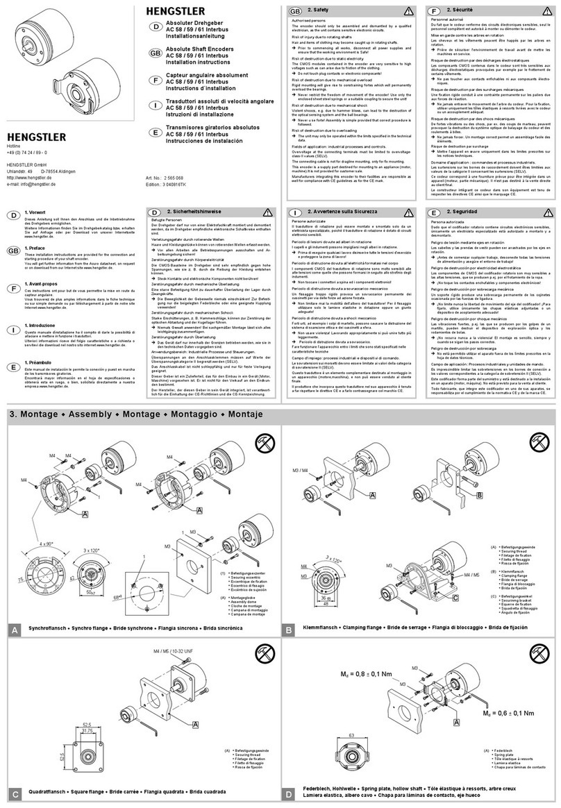
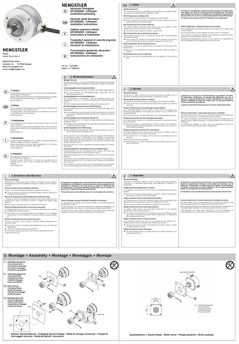
3. Montage  Assembly  Montage  Montaggio  Montaje
Quadratflansch  Square flange  Bride carrée  Flangia quadrata  Brida cuadrada Federblech, Hohlwelle  Spring plate, hollow shaft  Tôle élastique à ressorts, arbre creux
Lamiera elastica, albero cavo  Chapa para láminas de contacto, eje hueco
(1)  Befestigungsexzenter
 Securing eccentric
 Excentrique de fixation
 Eccentrico di fissagio
 Excéntrico de sujeción
(A)  Montageglocke
 Assembly dome
 Cloche de montage
 Campana di montaggio
 Campana de montaje
CD
(A)  Federblech
 Spring plate
 Tôle élastique à ressorts
 Lamiera elastica
 Chapa para láminas de contacto
(A)  Befestigungsgewinde
 Securing thread
 Filetage de fixation
 Filetto di fissaggio
 Rosca de fijación
(A)  Befestigungsgewinde
 Securing thread
 Filetage de fixation
 Filetto di fissaggio
 Rosca de fijación
(B)  Klemmflansch
 Clamping flange
 Bride de serrage
 Flangia di bloccaggio
 Brida de fijación
(C)  Befestigungswinkel
 Securinmg bracket
 Equerre de fixation
 Squadretta di fissaggio
 Ángulo de fijación
Klemmflansch  Clamping flange  Bride de serrage  Flangia di bloccaggio  Brida de fijación
AB
Synchroflansch  Synchro flange  Bride synchrone  Flangia sincrona  Brida sincrónica
Md= 0,6 ± 0,1 Nm
Md= 0,8 ± 0,1 Nm
4. Mechanische Daten
Mechanical data • Caractéristiques mécaniques
Dati meccanici • Datos mecánicos
d = 6 mm
d = 9,52/10 mm
- kurzzeitig
- short term
- brièvement
- per breve durata
- de corta dura-
ción
= 12 000 min-1
- Dauerbetrieb
- continuous duty
- Fonctionnement
ininterrompu
- Servizio continuo
- Funcionamiento
continuo
= 10 000 min-1
-40 ... +100 °C
- Vibration
- Shock
100 m/s² (10 ... 2 000 Hz)
1 000 m/s² (6 ms)
6.2 Begriffserläuterungen
Explanation of terms • Terminologie
Spiegazioni sui termini • Explicaciones de conceptos
Direction +UB2) =Aufsteigende Codewerte bei Drehung cw
Ascending code value when turning cw
Valeurs de code croissantes en rotation cw
Valori codice crescenti per giro in senso orario
Valores de código descendentes
0 V = Fallende Codewerte bei Drehung cw
Descending code value when turning cw
Valeurs de code décroissantes en rotation cw
Valori codice decrescenti per giro in senso orario
Girando en sentido de las manecillas de reloj
N.C. =Nicht belegt
Not Connected
Libre
Non collegato
Desconectado
LSB =Least Significant Bit
Least Significant Bit
Bit de poids faible
Least Significant Bit
Bit menos significativo
MSB =Most Significant Bit
Most Significant Bit
Bit de poids fort
Most Significant Bit
Bit más significativo
S0, S1, ... =Datenbits für Auflösung pro Umdrehung
Data bits for resolution per turn
Bits de données pour résolution par rotation
Bit-data per risoluzione al giro
Bits de datos para resolución por giro
M0, M1, ...
(Multiturn)
=Datenbits für die Anzahl der Umdrehungen
Data bits for number of turns
Bits de données pour le nombre de rotation
Bit-data per numero giro
Bits de datos para número de giros
6. Anschlussbilder
Connection diagrams • Symboles de raccrdement
Denominazione collegamento • Denominación de los
cables
6.1 Farbkürzel für Kabel
Colour code for cable • Abréviation de couleur de câble
Abbreviature per cavi • Abreviatura de color para cable
ID
bl blau blue bleu blu azul
br braun brown brun marrone marrón
ge gelb yellow jaune giallo amarillo
gn grün green vert verde verde
gr grau grey gris grigio gris
rs rosa pink rose rosa rosa
rt rot red rouge rosso rojo
sw schwarz black noir nero negro
vi violett violett violet viola violeta
ws weiß white blanc bianco blanco
2) LBaudrate
< 25 m < 1 MHz
< 50 m < 400 kHz
< 100 m <300 kHz
< 200 m <200 kHz
< 400 m <100 kHz
6.3 Kabel • cable • câble • Cavo • cable
Flanschdose 12p • Connector 12p • Boîte à bride 12p •
Connettore 12p • Caja de enchufe de brida 12p (CONIN)
Farbe / Colour Pin Signal
br 10V
rs 2Data
ge 3Clock
ws/ gn 4A+ (when ordering SC, BC)
bl 5Direction
rt/ bl 6B+ (when ordering SC, BC)
br/ gn 7A- (when ordering SC, BC)
ws 85V / 10-30V
gr/ rs 9B- (when ordering SC, BC)
gr 10 Data
gn 11 Clock
sw 12 0 V-signal output
Pin 1 und 2 verseilt • Pin 1 and 2 twisted pair
Pin 4 und 6 verseilt • Pin 4 and 6 twisted pair
Pin 3 und 7 verseilt • Pin 3 and 7 twisted pair
Pin 5 und 8 verseilt • Pin 5 and 8 twisted pair
Kabel • Cable
Art. No.: 3 280 251
M12 Stecker • M 12 Connector
Art. No.: 3 539 597
9. Identifikationscode
Ordering data • Code d´identification
Chiave per l´ordinazione • Código de pedido
2) oder unbeschaltet
or unattached
ou sans affectation
o non connesso
o non conectado
7. Störmeldung
Malfunction • Message d’erreur
Avviso di malfunzionamento • Aviso de falla
Die Betriebsbereitschaft des Drehgebers wird durch eine grüne LED
angezeigt. Nach Auftreten einer Störung wird diese durch eine rote
LED angezeigt.
Preset
Durch Drücken mit einem stumpfen Gegenstand auf die Preset-Taste
wird die Absolutposition ohne Zeitverzögerung auf den Presetwert
gesetzt. Das Verhalten ist dynamisch, d.h. der Preset Befehl wird
unabhängig davon, wie lange die Taste gehalten wird einmal beim
Beginn des Drückens wirksam. Die LED signalisiert jedoch das
Betätigen der Taste durch dauerndes rotes und grünes Leuchten für
die Dauer des Drückens.
The operational state of the encoder is displayed by a green LED. The
occurrence of a malfunction will be indicated by a red LED.
Preset
Press the Preset button with a blunt item to set the absolute position
without a time delay to the preset value. Behaviour is dynamic, i.e. the
preset command is independent of how long the button is held down
and is effective once the button is pressed. The LED however signals
the actuation of the button by a continuous red and green light while
the button is pressed.
LED
RESET
LED Encoder
Grün / Rot O.K. / Fehler
Green / Red O.K. / Error
Verte / Rouge O.K. / Erreur
Verde / Rosso O.K. / Malftn.
Verde / rojo O.K. / Falla
5. Elektrische Daten
Electrical data • Caractéristiques électriques
Dati elettrici • Datos eléctricos
Singleturn Multiturn
UB1) DC 5 V –5%/+10%
DC 10 ... 30 V
Imax (only Encoder) = 50 mA 100 mA
Imax (incl. Output) =
Fuse
150mAT 200 mAT
- Alarmausgang
- Alarm output
- Sortie d´alarme
- Carico dúscita
- Salida de alarma
SSI Alarm Bit
- Kabellänge3)
- Cable length3)
- Longueur de câble3)
- Lunghezza cavo3)
- Longitud de cable3)
DC 5 V max .10 m
DC 10 … 30 V max. 400 m 1) 2)
ESD
Verlängerungskabel mit Stecker • Extension cable with connector
3m Art.No. 1 565 313
5m Art.No. 1 565 314
10m Art.No. 1 565 315
Gegenstecker • Mating Connector: 12pin Conin
rechtsdrehend • clockwise Art.No. 3 539 202
linksdrehend • counterclockwise Art.No. 3 539 229
Kabel • Cable
Art. No.: 3 280 220
Verlängerungskabel mit Stecker • Extension cable with connector
rechtsdrehend • clockwise linksdrehend • counterclockwise
3m Art.No. 1 542 003 3m Art.No. 1 542 010
5m Art.No. 1 542 004 5m Art.No. 1 542 011
10m Art.No. 1 542 005 10m Art.No. 1 542 012
12
3
4
6
5
7
8
6.4 M12 Steckverbindung 8polig • M12 Eurofast Connector
8pole
Farbe / Colour Pin Signal
ws 110....30 Volt
br 20 Volt
3N.C.
gn 4Clock
rs 5Data
ge 6Clock
bl 7Direction
gr 8Data
PRESET
La disposición de servicio del codificador rotatorio se indica mediante
un diodo emisor de luz de color verde. La aparición de una falla se
indica mediante un diodo emisor de luz de color rojo.
Preset
Pulsando la tecla preset con un objeto sin punta, se efectúa la reposi-
ción sin posición absoluta del aviso de falla. El comportamiento es
dinámico, es decir, la orden de preset surte efecto una vez en el
momento de comenzar a pulsar, independientemente del tiempo que
se mantenga pulsada la tecla. Sin embargo, el diodo emisor de luz
indica, mediante una luz continua de color rojo o verde, que se ha
pulsado la tecla, emitiendo la luz durante el tiempo que se esté
pulsando la tecla.
Un led verde indica che il trasduttore di rotazione è pronto a funziona-
re. Alla comparsa di un malfunzionamento lo stesso viene segnalato
da un led rosso.
Preset
Premendo il pulsante di preset con un oggetto spuntato, l’avviso di
posizione assoluta viene immediatamente resettato. La reazione è
dinamica, sarebbe a dire che il comando di preset è valido al momento
in cui si agisce sul pulsante e non dipende da quanto tempo che lo si
tiene premuto. Tuttavia Il led segnala che è stato azionato il pulsante
con luce rossa o verde continua e per tutto il tempo che lo si tiene
premuto.
Une DEL verte indique que le codeur est prêt à fonctionner. Une DEL
rouge indique qu’une erreur est survenue.
Preset
La position absolue est remis à zéro sans retard en appuyant sur la
touche Preset au moyen d’un objet émoussé. Ce comportement est
dynamique, c.-à-d. que l’ordre de remise à zéro est effectif dès qu’on
appuie sur la touche, sans tenir compte de la durée d’actionnement. La
DEL signale toutefois que la touche est maintenue enfoncée en restant
allumée en permanence en rouge et en vert.
L
9.1 Deutsch
9.1 English
ADDRESS MAP
Bank 0: configuration Memory
Bank 1: manufactory Memory
Bank 2: manufactory EDS General
Bank 3: manufactory EDS Profile BP1
Bank 4 - 7: OEM Memory
Speicher kann überschrieben werden!
Bitte beachten, dass Bank 0, 1, 2 und 3 nicht beschrieben werden dürfen.
Memory can be overwritten!
Please not that Bank 0, 1, 2 and 3 are not allowed to be accessed.
Attention
Für BiSS-C / For BiSS-C
Typ Auflösung1) 2) 3) Versorgung4) Flansch, Schutzart, Welle5) 6) Schnittstelle7) 8) Anschluss9)
AC58
0010 10 Bit ST
0012 12 Bit ST
0013 13 Bit ST
0014 14 Bit ST
0017 17 Bit ST
0019 19 Bit ST
0022 22 Bit ST
0360 360 Schritte ST
0720 720 Schritte ST
1212 12 Bit MT +
12 Bit ST
1213 12 Bit MT +
13 Bit ST
1214 12 Bit MT +
14 Bit ST
1217 12 Bit MT +
17 Bit ST
1219 12 Bit MT +
19 Bit ST
1222 12 Bit MT +
22 Bit ST
A DC 5 V
E DC 10 - 30 V
S.41 Synchro, IP64, 6 mm
S.71 Synchro, IP67, 6 mm
K.42 Klemm, IP64, 10 mm
K.46 Klemm, IP64, 9.52 mm
K.72 Klemm, IP67, 10 mm
K.76 Klemm, IP67, 9,52 mm
F.42 Federblech, IP64, einseitig
offene Hohlwelle 10 mm,
Befestigung durch Klemmring
F.46 Federblech, IP64, einseitig
offene Hohlwelle 9.52 mm,
Befestigung durch Klemmring
F.47 Federblech, IP64, einseitig
offene Hohlwelle 12 mm,
Befestigung durch Klemmring
Q.42 Quadrat, IP64, 10 mm
Q.46 Quadrat, IP64, 9.52 mm
Q.72 Quadrat, IP67, 10 mm
Q.76 Quadrat, IP67, 9.52 mm
BI BiSS-B
BC BiSS-B + SinCos 1Vss
BE BiSS-C
BV BiSS-C + SinCos 1Vss
SG SSI Gray
SC SSI Gray + SinCos 1Vss
SB SSI Binär
SD SSI Binär + SinCos
1Vss
SR SSI Binär + high active
Preset
SH SSI Gray + high active
Preset
A Kabel axial
B Kabel radial
C M23-Stecker (Conin), 12-polig,
axial, cw
D M23-Stecker (Conin), 12-polig,
radial, cw
G M23-Stecker (Conin), 12-polig,
axial, ccw
H M23-Stecker (Conin), 12-polig,
radial, ccw
7 M12-Stecker, 8-polig, axial
8 M12-Stecker, 8-polig, radial
1)Auflösung 360 Schritte ST mit Offset 76 (Wertebereich 76...435)
2)Auflösung 720 Schritte ST mit Offset 152 (Wertebereich 152...871)
3)Preset bei Auflösung 360 und 720 Schritte ST nicht zulässig
4)Max. Kabellänge bei DC 5 V: 10 m
5)Schutzart IP67 nicht erhältlich in Kombination mit Presettaste und LED-Anzeige
6)Schutzart IP67 in Kombination mit Stecker wird nur garantiert bei ordnungsgemäßem Anschluss eines IP67 Gegensteckers
7)Alarm und Parity Bit auf Anfrage
8)Schnittstelle BC, BV, SC oder SD nicht mit Anschluss 7 und 8 (M12)
9)Anschluss 7 und 8 (M12) bei Quadratflansch nur für IP64 und 10x19,5 mm - Welle
Type Resolution1) 2) 3) Supply
Voltage4) Flange, Protection, Shaft 5) 6) Interface7) 8) Connection9)
AC58
0010 10 Bit ST
0012 12 Bit ST
0013 13 Bit ST
0014 14 Bit ST
0017 17 Bit ST
0019 19 Bit ST
0022 22 Bit ST
0360 360 increments ST
0720 720 increments ST
1212 12 Bit MT +
12 Bit ST
1213 12 Bit MT +
13 Bit ST
1214 12 Bit MT +
14 Bit ST
1217 12 Bit MT +
17 Bit ST
1219 12 Bit MT +
19 Bit ST
1222 12 Bit MT +
22 Bit ST
A DC 5 V
E DC 10 - 30 V
S.41 Synchro, IP64, 6 mm
S.71 Synchro, IP67, 6 mm
K.42 Clamping, IP64, 10 mm
K.46 Clamping, IP64, 9.52 mm
K.72 Clamping, IP67, 10 mm
K.76 Clamping, IP67, 9.52 mm
F.42 Spring tether, IP64, hub shaft
10 mm, mounting with front
clamping ring
F.46 Spring tether, IP64, hub shaft
9.52 mm, mounting with front
clamping ring
F.47 Spring tether, IP64, hub shaft
12 mm, mounting with front
clamping ring
Q.42 Square, IP64, 10 mm
Q.46 Square, IP64, 9.52 mm
Q.72 Square, IP67, 10 mm
Q.76 Square, IP67, 9.52 mm
BI BiSS-B
BC BiSS-B + SinCos 1Vpp
BE BiSS-C
BV BiSS-C + SinCos 1Vpp
SG SSI Gray
SC SSI Gray + SinCos 1Vpp
SB SSI Binary
SD SSI Binary + SinCos
1Vpp
SR SSI Binary + high active
Preset
SH SSI Gray + high active
Preset
A Cable axial
B Cable radial
C M23 connector (Conin),
12 pole, axial, cw
D M23 connector (Conin),
12 pole, radial, cw
G M23 connector (Conin),
12 pole, axial, ccw
H M23 connector (Conin),
12 pole, radial, ccw
7 M12 connector, 8 pole, axial
8 M12 connector, 8 pole, radial
1)Resolution 360 increments ST with Offset 76 (value range 76...435)
2)Resolution 720 increments ST with Offset 152 (value range 152...871)
3)Preset not allowed at resolutions of 360 and 720 increments ST
4)Max. cable length for DC 5 V: 10 m
5)Protection class IP67 not available in combination with preset key and LED display
6)Protection class IP67 on cover with connector only if IP67 mating connector mounted properly
7)Alarm- and/ or Parity-Bit on request.
8)Interface “BC“, „BV“, „SC“ or „SD“ not with connection "7" and "8" (M12)
9)Connection code "7" and "8" (M12) with square flange only for IP64 and 10x19.5 mm shaft
All specifications are subject to change without prior notice.
Attention
1) Der Encoder ist zum Anschluss an ein SELV Netzteil vorgesehen.
Es ist nicht zulässig, dass der Encoder direkt an ein Gleichspannungsnetz angeschlos-
sen wird.
This encoder is designed for a connection to a SELV power supply.
It is not allowed to connect the encoder to a direct current line voltage.

This manual suits for next models

2

Other Hengstler Media Converter manuals

Hengstler RI 32 User manual

Hengstler

Hengstler RI 32 User manual

Hengstler AC 58-I SSI User manual

Hengstler

Hengstler AC 58-I SSI User manual

Hengstler AC 58 Profibus User manual

Hengstler

Hengstler AC 58 Profibus User manual

Hengstler AC 58 Interbus User manual

Hengstler

Hengstler AC 58 Interbus User manual

Hengstler AC 58 Parallel User manual

Hengstler

Hengstler AC 58 Parallel User manual

Hengstler RI 42 User manual

Hengstler

Hengstler RI 42 User manual

Hengstler AD58 DRIVE-CliQ User manual

Hengstler

Hengstler AD58 DRIVE-CliQ User manual

Hengstler RI 36-H User manual

Hengstler

Hengstler RI 36-H User manual

Hengstler AX71 Series User manual

Hengstler

Hengstler AX71 Series User manual

Hengstler RI 58-D User manual

Hengstler

Hengstler RI 58-D User manual

Hengstler AC 58 SUCOnet User manual

Hengstler

Hengstler AC 58 SUCOnet User manual

Hengstler RX70TPRX /RX 71TP User manual

Hengstler

Hengstler RX70TPRX /RX 71TP User manual

Hengstler AX65 User manual

Hengstler

Hengstler AX65 User manual

Hengstler AX73 User manual

Hengstler

Hengstler AX73 User manual

Hengstler AC 58 DeviceNet User manual

Hengstler

Hengstler AC 58 DeviceNet User manual

Hengstler DRIVE-CliQ AD58S User manual

Hengstler

Hengstler DRIVE-CliQ AD58S User manual

Hengstler AC58 User manual

Hengstler

Hengstler AC58 User manual

Hengstler RI 36 User manual

Hengstler

Hengstler RI 36 User manual

Hengstler RI 58-F User manual

Hengstler

Hengstler RI 58-F User manual

Hengstler AR 60 Series User manual

Hengstler

Hengstler AR 60 Series User manual

Hengstler AC 58 User manual

Hengstler

Hengstler AC 58 User manual

Hengstler ACURO AR 60 User manual

Hengstler

Hengstler ACURO AR 60 User manual

Hengstler RA 58-P User manual

Hengstler

Hengstler RA 58-P User manual

Hengstler RA 58-P User manual

Hengstler

Hengstler RA 58-P User manual

Popular Media Converter manuals by other brands

Inline 76670I user manual

Inline

Inline 76670I user manual

EuroLite Node 8 user manual

EuroLite

EuroLite Node 8 user manual

Digi One SP quick start guide

Digi

Digi One SP quick start guide

prophecy gofanco PRO-MSTDP3HD user guide

prophecy

prophecy gofanco PRO-MSTDP3HD user guide

Audio Note DAC 0.1x Homeowner's information

Audio Note

Audio Note DAC 0.1x Homeowner's information

Behringer DS2800 quick start guide

Behringer

Behringer DS2800 quick start guide

Yamaha YMC10 owner's manual

Yamaha

Yamaha YMC10 owner's manual

Cabletime Mediastar 798 quick start guide

Cabletime

Cabletime Mediastar 798 quick start guide

Drok LM2596 quick start guide

Drok

Drok LM2596 quick start guide

Becker BD406 Operator's manual

Becker

Becker BD406 Operator's manual

Baumer HOG 75 K Installation and operating instructions

Baumer

Baumer HOG 75 K Installation and operating instructions

Cypress CDL-125 Operation manual

Cypress

Cypress CDL-125 Operation manual

Monoprice Blackbird 15252 user manual

Monoprice

Monoprice Blackbird 15252 user manual

Midian Electronics MTSD-3 manual

Midian Electronics

Midian Electronics MTSD-3 manual

Scopus CODICO IRD-2600 user manual

Scopus

Scopus CODICO IRD-2600 user manual

Lake People DAC RS 06 user manual

Lake People

Lake People DAC RS 06 user manual

B&B ILinx 485DRCI-PH quick start guide

B&B

B&B ILinx 485DRCI-PH quick start guide

Full Gauge TCP-485 instruction manual

Full Gauge

Full Gauge TCP-485 instruction manual

manuals.online logo
manuals.online logoBrands
  • About & Mission
  • Contact us
  • Privacy Policy
  • Terms and Conditions

Copyright 2025 Manuals.Online. All Rights Reserved.