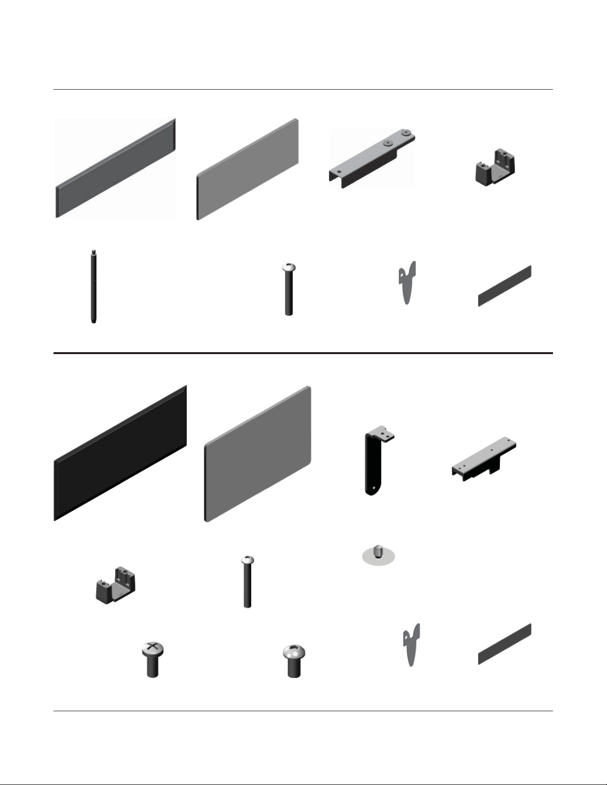
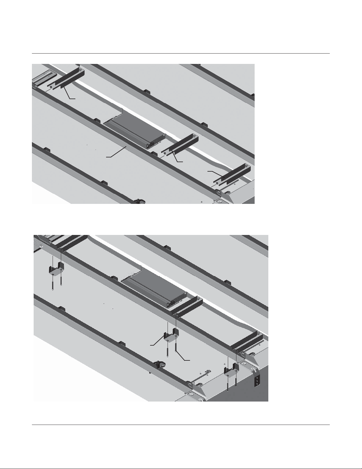
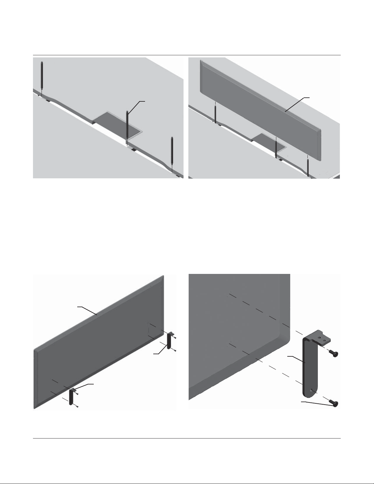
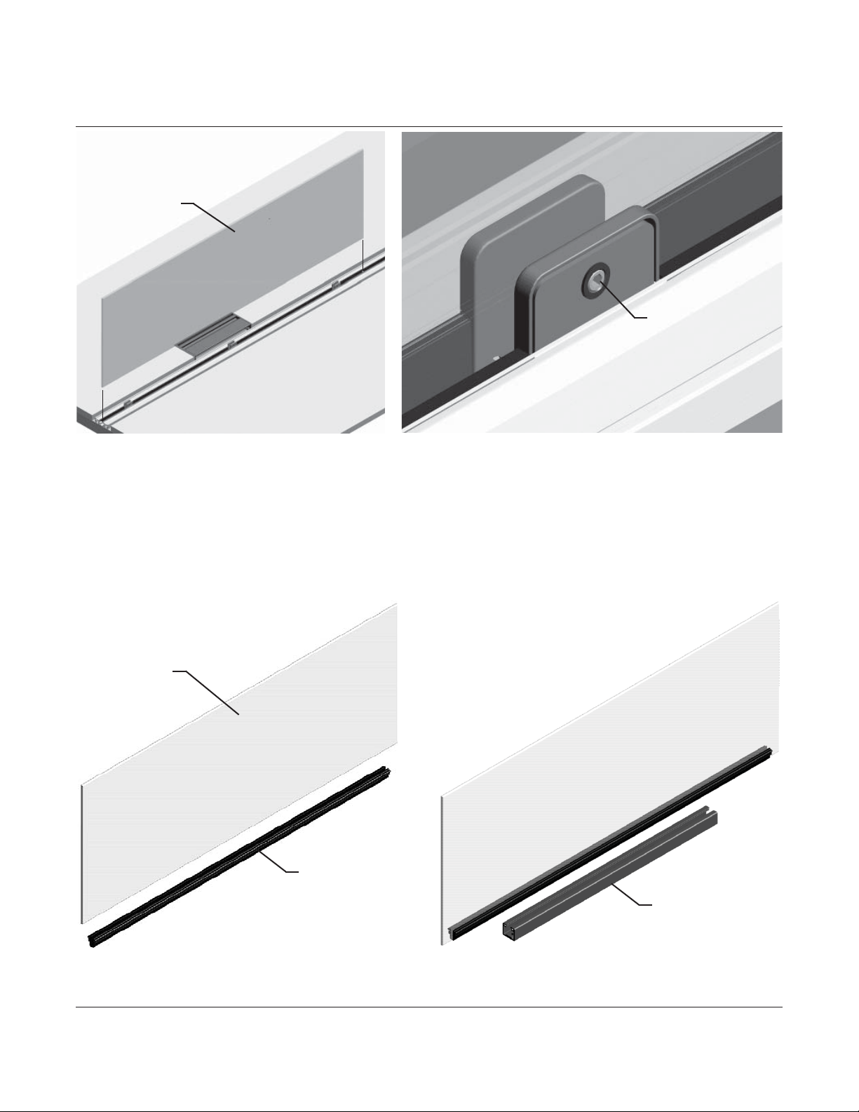
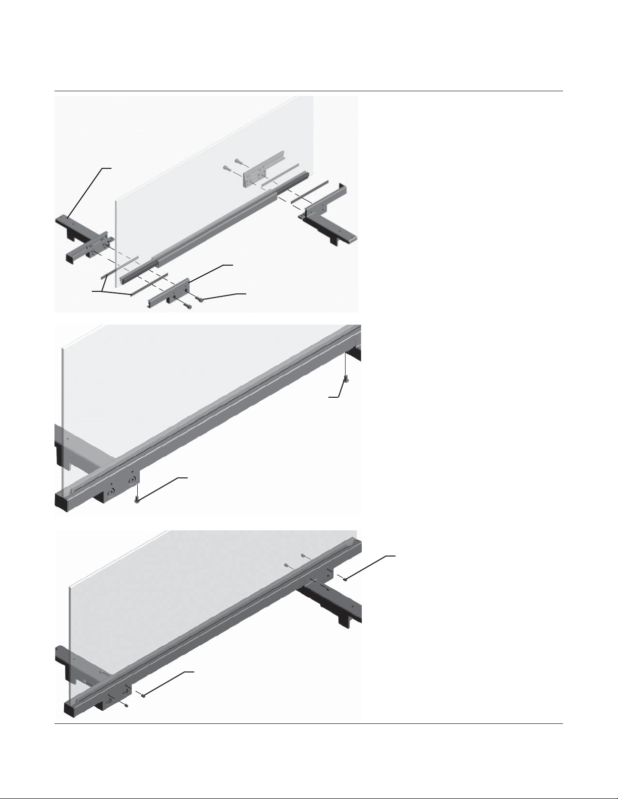
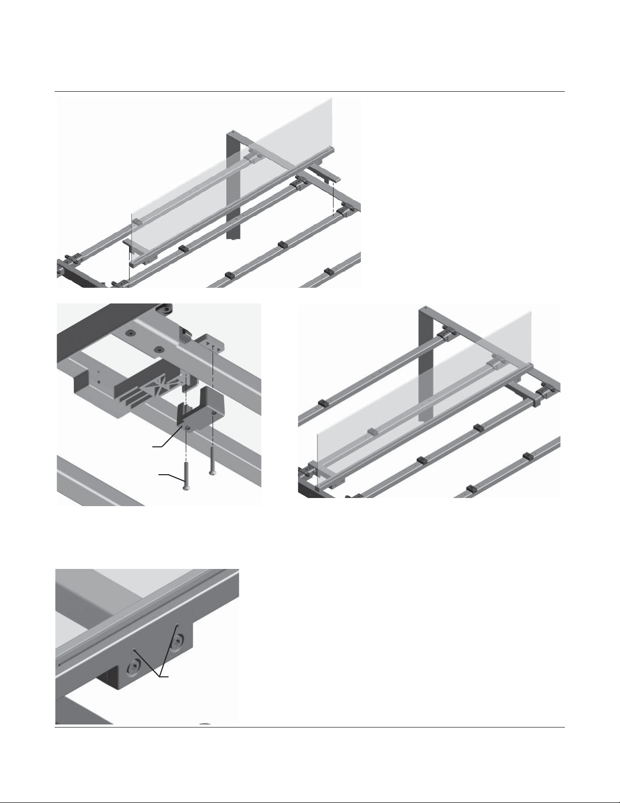
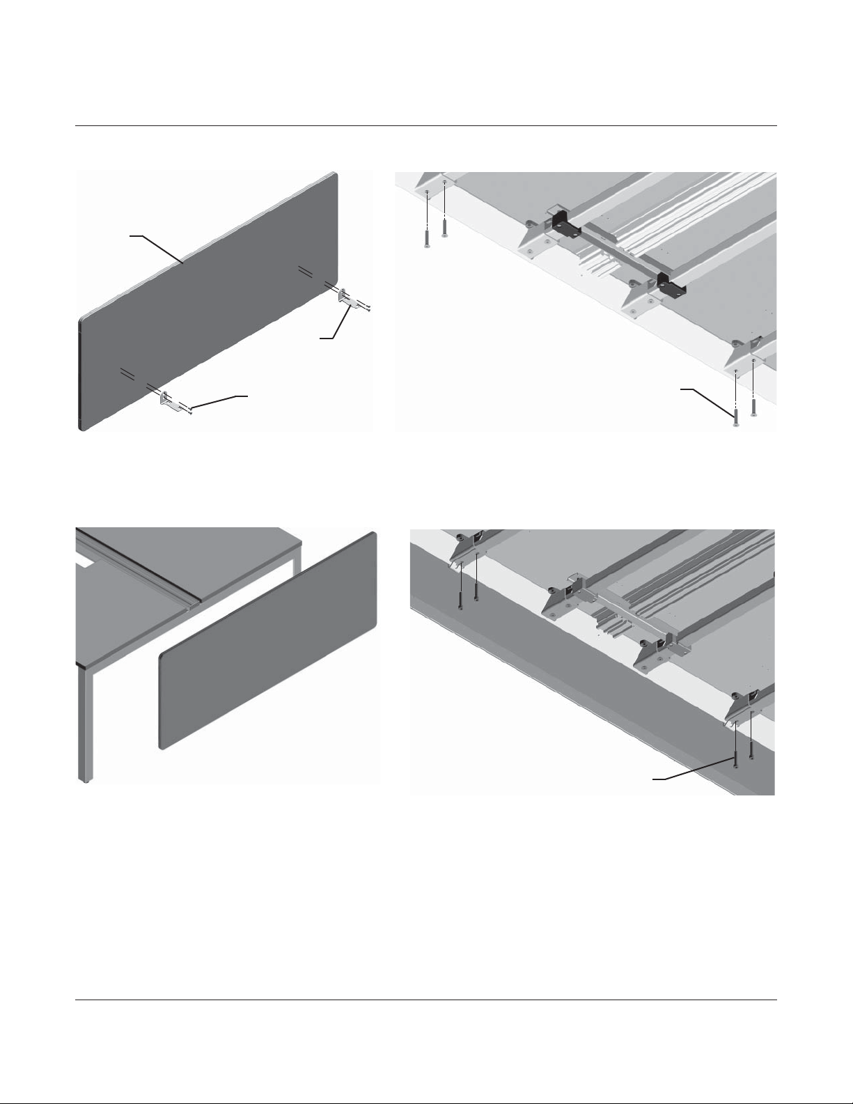
Herman Miller Layout Studio GNSDXT Series Installation instructions


This manual suits for next models
12
Other Herman Miller Indoor Furnishing manuals

Herman Miller
Herman Miller Renew User manual

Herman Miller
Herman Miller Nevi Link Guide

Herman Miller
Herman Miller 1BNX5K - J User manual

Herman Miller
Herman Miller Aeron Installation instructions

Herman Miller
Herman Miller Aeron User manual

Herman Miller
Herman Miller Vista Installation instructions

Herman Miller
Herman Miller Envelop User manual

Herman Miller
Herman Miller Canvas Office Landscape Installation instructions

Herman Miller
Herman Miller Canvas Office Landscape Installation instructions

Herman Miller
Herman Miller Sayl User manual

Herman Miller
Herman Miller Aria Desk User manual

Herman Miller
Herman Miller Canvas Vista Credenza Installation instructions

Herman Miller
Herman Miller OE1 User manual

Herman Miller
Herman Miller Ubi Work Tools Installation instructions

Herman Miller
Herman Miller Layout Studio Installation instructions

Herman Miller
Herman Miller Verus Task Chair Installation instructions

Herman Miller
Herman Miller Noguchi Rudder Coffee Table User manual

Herman Miller
Herman Miller Setu Maintenance manual

Herman Miller
Herman Miller Sayl User manual

Herman Miller
Herman Miller Verus Task Chair Installation instructions


Popular Indoor Furnishing manuals by other brands


Living Spaces
Living Spaces Willow Creek Nightstand Assembly instructions

Salamander Designs
Salamander Designs SYNERGY DOUBLE-WIDTH SHELF SA/DS quick start guide

Keter
Keter 416L 110 US GAL Assembly instructions

Otto
Otto LKZ 41332 quick start guide

IKEA
IKEA KULLABERG manual

bauhaus
bauhaus EDGE installation instructions

Hinkle Chair Company
Hinkle Chair Company Glider 854 instruction manual

Gima
Gima 28516 Use and maintenance book

INTER LINK SAS
INTER LINK SAS 19 300 340 Assembling Instruction

Winners Only
Winners Only BFC2001CK Assembly instructions

Somopar
Somopar HOME ATACAMA 2.0 instruction manual

WIEMANN
WIEMANN 991345 quick start guide