HMS TYTAN 15 User manual

MANUAL INSTRUCTION
TYTAN 15
HOME GYM
EN
hms-tness.com

2hms-tness.com
NOTES CONCERNIGN SAFETY
This product is intended only for home use and has been designed to ensure opmal safety.
The following rules shall be obeyed:
1. Before starng your workout, consult your physician to check if there are any reasons prevenng the use of this tness equip-
ment. The doctor’s decision is required if you take medicines that aect your heart work, blood pressure and levels of cholesterol.
It is also necessary in the case of persons aged over 35 and people with health problems.
2. Always do your warm-up before training.
3. During exercise and aer its compleon the training equipment should be protected from children and animals.
4. The equipment shall be placed on dry, stable and properly levelled surface. All sharp objects shall be removed from its direct
vicinity. The equipment should be protected from humidity. Possible surface irregularies should be levelled. It is recommended
to use special an-slip base to prevent the equipment displacement during workout.
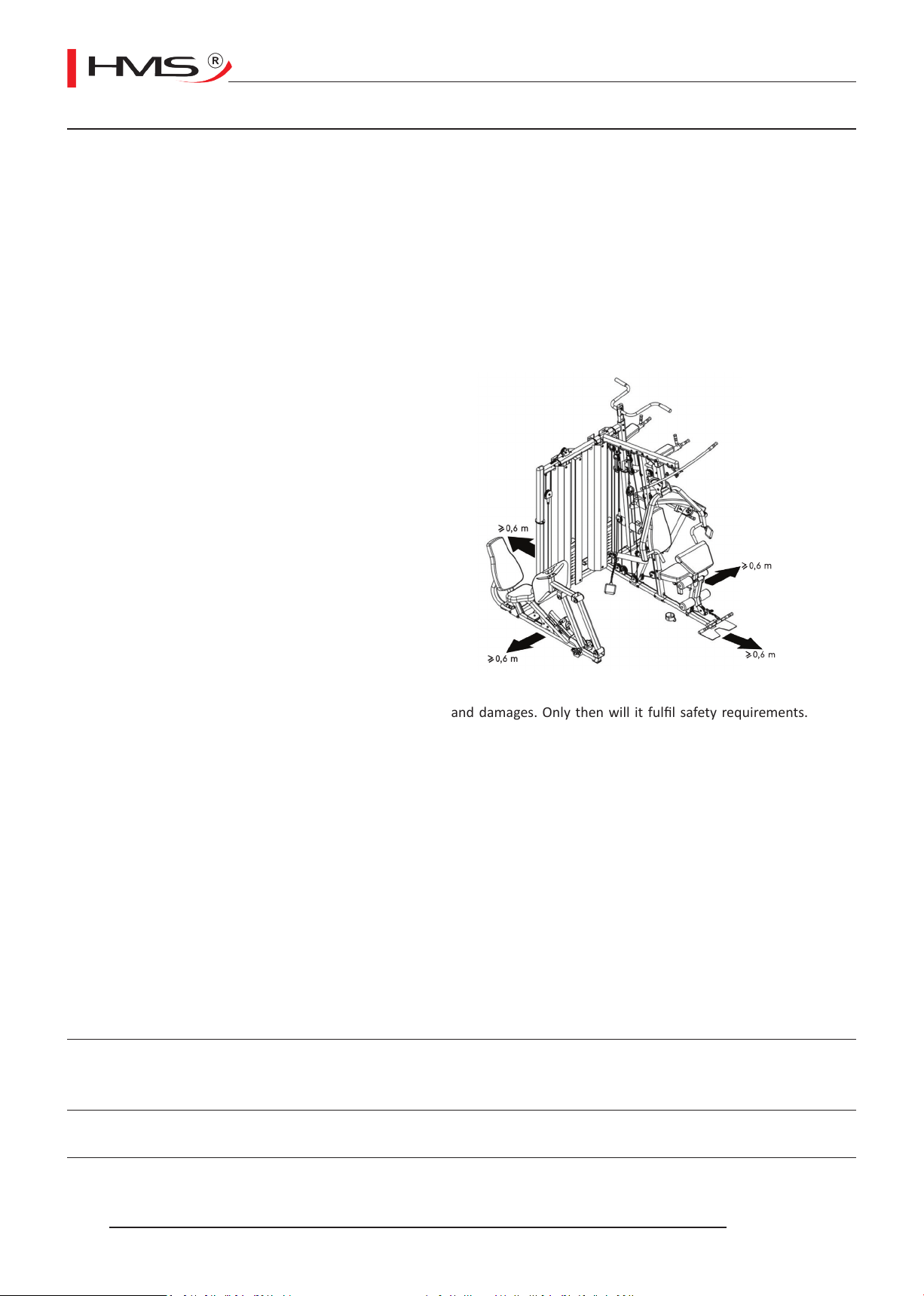
5. Free space should not be smaller than 0.6 m and
greater. Pay aenon to worrying signals. Incor-
rect or excessive exercising means health hazard.
If headache or dizziness, chest pain, irregular heart
rhythm or other worrying symptoms appear during
training, the workout shall be stopped immediately
and a doctor shall be consulted. Incorrect or over-in-
tensive training can lead to traumas.
6. than the training space available in direcons of
the equipment accessibility. Free space must also
include space for emergency quing. If dierent
pieces of equipment are located side by side, the
size of free space can be divided.
7. Before the rst use, and later at regular intervals,
ghtness of all screws, bolts and other joints shall
be checked.
8. Before starng your exercise, check xing of parts
and joints between them. Workout can be started
only if the equipment is fully operaonal.
9. The equipment shall be regularly checked for wearing-out and damages. Only then will it full safety requirements. Special
aenon shall be paid to foam grips, caps on legs and upholstery, which are all fast wearing parts. Damaged parts shall be imme-
diately repaired or replaced. Unl then, the training equipment cannot be used.
10. Do not put any elements into openings.
11. Pay aenon to protruding adjustment devices and other structural elements that might hinder exercise.
12. The equipment can only be used according to its intended purpose. If any parts wears out or is damaged, or if you hear wor-
rying sounds when using the equipment, you should immediately stop exercising. Do not use the equipment again unl the pro-
blem is removed.
13. Wear comfortable clothes and sport shoes for training. Avoid loose clothes that might catch protruding parts of the equipment
or limit your mobility.
14. The equipment falls into class H according to standard EN ISO 20957-1 and is intended for home use only. It cannot serve the-
rapeuc, rehab or commercial purposes.
15. When liing or moving the equipment, maintain correct posture to avoid spine injuries.
16. The product is intended for adults only. Keep children without supervision away from the equipment.
17. During installaon, follow closely the aached manual instrucon and use only such parts that have been included in the pac-
kage. Before installaon, check if all parts from the list are included in the package.
WARNING: READ THE INSTRUCTION BEFORE USING THE EQUIPMENT.
WE ARE NOT REPONSIBLE FOR INJURIES OR DAMAGES TO OBJECTS CAUSED BY INCORRECT USE OF THE PRODUCT
MAINTENANCE: No aggressive cleaning agents shall be used to clean the equipment. Use a so, wet cloth to remove dirt and dust. The
equipment shall be kept in dry places and protected from humidity and corrosion.
TECHNICAL DATA: Net weight – 370 kg
Dimensions when unfolded – 246 x 332 x 218 cm
Maximum permissible loading of the product – 140 kg

3
hms-tness.com
LIST OF PARTS

4hms-tness.com

5
hms-tness.com
ASSEMBLY
1. A washer should be placed on both ends of all bolts (bolt heads and nuts) unless otherwise specied in this instrucon.
2. Tighten all bolts manually at inial stage. Use relevant tool to ghten the screws only when a given element has been fully
assembled.
3. Some elements may be pre-assembled at the factory.
4. 2 persons are required to assemble the machine.

6hms-tness.com
STEP 1
STEP 2
1. Fasten the buer (89) to parts (2 and 123) with screw (108).
2. Insert the guide (11) into openings of part (123) and fasten with bolts (96).
1. Fix the buer (89) to the boom main frame (3) with a bolt (108).
2. Insert the tube (22) into the opening in the side secon of the plaorm (21) and boom part of the fra-
me (3).
3. Level the openings in both parts (22 and 3) and drive in the pin (35).
4. Put end caps (67) on both ends of the tube (21) and end caps (70) of the frame (3).

7
hms-tness.com
STEP 3
1. Connect the frame (123) with the frame (2) using a bolt (103), washers (115) and nut (118).
2. Insert terminals (71) onto the arm (1) and (2).
3. Connect the arm (123) and arm (2) with the frame (3) and arm (1) using screws (103), washers (115) and
nuts (118).
4. Fix the buer (89) to the leg press frame (121).
5. Connect the frame (121) with other frames (123, 2, 1, 3) using screws (154), washers (114) and nuts
(118). Install the plate at the same me.
6. Put the end cap (69) on the frame (121).

8hms-tness.com
STEP 4
1. Put end cap (176) on the frame (158) and the buer (70) on the frame (4).
2. Fix the frame (130) to the frame (123); frame (158) to the frame (2); frame (4) to the frame (3) using
screws (103), washers (114) and nuts (118).

9
hms-tness.com
STEP 5
1. Install absorbers (56) on the guide (11). Next, x the weights (51 and 50).
Cauon: be careful when xing the weights. Do not li more than one weight at a me!
2. Li weight (50) and insert selector (52) into the weights (51).
3. Inset ange (53) on the selector (52) and drive the pin (55) through the ange (53) and selector (52),
carefully placing the weight (50) on the stack. Lock it with the safety pin (36) and insert a washer (54).

10 hms-tness.com
STEP 6
1. Connect the frame (130) with frame (129) using screws, washers and nuts (96, 114, 118).
2. Put the frame (122) on the guide (11) and fasten it with screws (96) with washers (115). Fasten it with
the frame (129) using screws (96), washers (114) and nuts (118), leaving slight clearance on the screws.
3. Put part (173) on frame (157). Next, connect the frame (157) with the frame (158) using screws, washers
and nuts (96, 114, 118).
4. Put boom cover support (17) and absorbers (56) on the frame (2).
5. Insert the guide (12) into the frame (2).
6. Install weights (50 and 51) on the guide (12) with the help from another person.
7. Set elements (52, 53 and 55) and then lock them with safety pin (38). Insert the washer (54).
8. Insert the frame (5) on the guide (12).
9. Fasten the frame (5) to guides (12) using screws (96) and washers (115).
10. Connect the frame (5) with frame (122) using screws, washers and nuts (96, 114, 118), leaving slight cle-
arance on screws. Connect the frame (5) with frame (157) using screws, washers and nuts (101, 114, 118)
and ghten all screws.

11
hms-tness.com
STEP 7
1. Fix elements (14, 120 and 116) to frame (6).
2. Connect the frame (6) with frame (4) and ghten using screws, washers and nuts (100, 114, 118), leaving
slight clearance on screws.
3. Connect the frame (6 and 4) with frame (5) using screws, washers, reinforcing plate and nuts (101, 114,
29, 118).
4. Fasten top cover supports (166) to the frame (5) with screws (94), leaving slight clearance unl the mo-
unng of covers (39) in step 29.
ON COMPLETION OF THESE ACTIVITIES, TIGHTEN ALL SCREWS FROM STEP 6 AND 7 (except
for subpoint 4).

12 hms-tness.com
STEP 8
STEP 9
1. Connect the arm of the pulley tackle (8) with frame (3) using screws, washers and nuts (103, 114 and
118), leaving slight clearance on screws and xing the arm (4) with screws, washers and nuts (100, 114,
118). Next, ghten all screws all the way.
1. 1. Place arms (9) on the frame (8), lubricang the tucked-in part; lock both arms (9) with retaining rings
(86).

13
hms-tness.com
STEP 10
1. Place the arm (24) on the frame (6), levelling the openings between the elements by inserng the roller
(30) and fasten using screws and washers (95, 117).
2. Put foam rollers (165) on the handles of press arm (aer soaking them in warm water). Install part (66
and 69).
3. Put arm (13) on the frame (24). Level the openings and insert the roller (31). Fasten with screws (95) and
washers (117).
4. Insert the end cap (82).

14 hms-tness.com
STEP 11
1. Put sleeves (64) on the seat frame (16).
2. Fasten the frame (16) to frame (4) using screws, washers and nuts (100, 14, 118).
3. Connect with frame (3) using screws, washers and nuts (103, 114, 118). Tighten hard.
4. Drive the buer (72) into the arm (15) and insert the roller (19).
5. Mount the arm (15) on the frame (16). Level the openings and fasten using screws, washers and nuts
(104, 114, 118). Insert end caps (73). Adjust the screws so that the leg press arm (15) can move freely.
1. Fix the backrest (42) to the frame (25) using screws, washers and nuts (96, 114, 73).
2. Install everything on the arm (4) using screws, washers and nuts (105, 116, 119). Put on end caps (74).
Adjust the screws so that the arm can easily be adjusted.
3. Fix end cap (81).
STEP 12

15
hms-tness.com
STEP 13
1. Fasten the seat (40) to support (20) using screws and washers (94, 111). Fix part (68).
2. Please the seat support (20) in the frame (16) and lock it with (61).
1. Fasten the preacher curl pad (41) to support (18) using screws and washers (92, 110).
2. Drive the support (18) along with the preacher curl pad into the frame (16) and secure it with safety
pin (88).
3. Insert the roller (23) into the frame (16) and arm (15); put on end caps (66).
4. Put on foam rollers (63).
STEP 14

16 hms-tness.com
STEP 15
1. Put end cap (69) on the frame (165).
2. Fasten the grips (161) to the frame (165) using
screws, washers and nuts (153, 114, 118).
3. Drive the whole unit into the frame (157) to the de-
sired height and fasten using screws, washers and nuts
(99, 114, 118).
STEP 16
1. Put on end caps with openings (180) and grips (77) on
the le (159) and right (160) bar.
2. Fasten both bars to the frame (157) using screws,
washers and nuts (100, 114, 118).
3. Fix bars (164) and grips (77) to both bars using screws
and washers (96, 115). Carefully ghten all screws.

17
hms-tness.com
STEP 17
1. Fasten the backrest (163) to the frame (157) with screws and washers (182, 112).
2. Fasten the armrests (162) to the bars (159 and 160) with screws and washers (181, 112).
STEP 18
1. Put end caps (174, 178) on the bench frame (167).
2. Fasten the bench backrest (168) bending it slightly to the frame (167) using screws and washers (92,
110).
3. Drive the roller (170) into the frame (167). Put on the grips (77). Set the roller in central posion and
ghten with the knob (177).
4. Drive the roller (169) into the frame (167). Put on end caps (66) and place foam rollers (175).
5. Drive the roller (169) into the frame (158) to the desired height. Put on end caps (66) and foam rollers
(175).

18 hms-tness.com
STEP 19
1. Using two screws (155), four washers (116) and two
nuts (119), x the bearing (144) on the main frame of
the leg press post (121). Note: do not ghten all the
way.
2. Set the openings in bearings (144) with the openings
turned upwards for potenal lubricaon.
STEP 20
1. Put end cap (69) on the frame (131).
2. Level the openings of the bearing (144),
frame (131) and frame (127).
3. Drive the roller (138) into the openings
of the bearing (144), frame (131) and frame
(127), and lock with screw (151).
4. Tighten the Allen screws on the bearing
rings (144).

19
hms-tness.com
STEP 21
1. Fix the oil absorber (136) to the arm (127) and frame (131) using two screws M6*25 (148) and nuts M6
(156).
STEP 22
1. Fasten the screw (149) into openings in parts (127 and 131), aer levelling them.

20 hms-tness.com
STEP 23
1. Drive end cap (146) into the frame
(131).
STEP 24
1. Level the openings in the arm (126) and main frame (121). Insert the roller (137). Put on bushings (139)
on both sides and x with Allen screws (150) and washers (147).
2. Level the openings in the arm (126). Insert the roller (137) and put on bushings (139), xing them with
allen screws and washers (150, 147).
3. Level the openings in the arm (127) and frame (133). Insert the roller (137) and put on bushings (139),
xing them with Allen screws and washers (150, 147).
4. Fix the plaorm (128) on the arm (133) and fasten with screws and washers (96, 114).
Table of contents
Other HMS Home Gym manuals