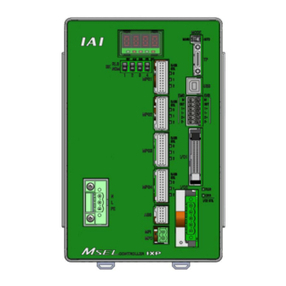
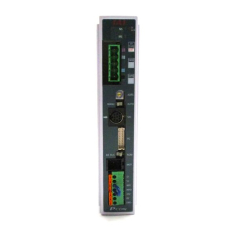
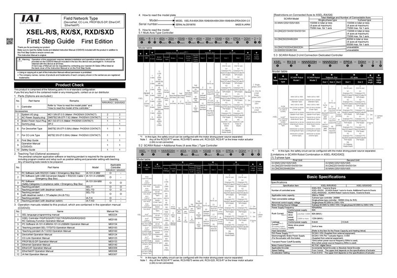
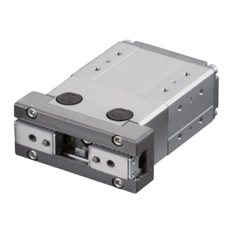
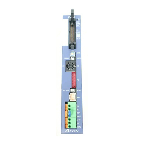
IAI ASEP User manual

ASEP/PSEP/DSEP
First Step Guide Eighth Edition
Thank you for purchasing our product.
Make sure to read the Safety Guide and detailed Instruction Manual (DVD) included with the product in addition to
this First Step Guide to ensure correct use.
This Instruction Manual is original.
Using or copying all or part of this Instruction Manual without permission is prohibited.
The company names, names of products and trademarks of each company shown in the sentences are registered
trademarks.
Product Check
This product is comprised of the following parts if it is of standard configuration.
If you find any fault in the contained model or any missing parts, contacts us or our distributer.
1. Parts
No
.
Part Name Model Reference
1 Controller Refer to “How to read the model plate”,
“How to read the model of the controlle
r
.”
Accessories
2 I/O Flat Cable Standard t
y
pe CB-APSEP-PIO*** ***shows the cable len
g
th
Dust-proof type
(
Equivalent to IP53
)
CB-APSEPW-PIO*** ***shows the cable length
3 Power Connector MC1.5/5-ST-3.5
(
Supplier : PHOENIX CONTACT
)
Applicable Cable Size
0.75 to 2mm2
(
AWG18 to 14
)
4 Space
r
PFP-S
(
Supplie
r
: OMRON
)
5 Absolute Battery Unit
(For Simplified Absolute Type Only) SEP-ABUM
(
Standard t
y
pe
)
SEP-ABUM-W
(
Dust-proof t
y
pe
)
6 First Step Guide ME0266
7 Instruction Manual
(
DVD
)
8 Safet
y
Guide M0194
2. Teaching Tool (to be purchased separately)
For the setups such as position setting and parameter setting using the teaching operation, the teaching
tool is required. Please prepare either of the following teaching tools.
No
.
Part Name Model
1 PC Software
(
Includes RS232C Exchan
g
e Adapter + Peripheral Communication Cable
)
RCM-101-MW
2 PC Software
(
Includes USB Exchan
g
e Adapter + USB Cable + Peripheral Communication Cable
)
RCM-101-USB
3 Touch Panel Teaching Pendant TB-01
(Standard Type / Deadman Switch Attached on the Left side Type / Deadman
Switch Attached on the Ri
g
ht side T
y
pe
)
TB-01/TB-01D/TB-01DR
4 Touch Panel Teaching Pendant TB-02
(
Standard T
y
pe / Deadman Switch T
y
pe
)
TB-02/TB-02D
5 Touch Panel Teachin
g
Pendant TB-03 Wired Lin
k
TB-03
3. Instruction manuals related to this product, which are contained in the instruction manual (DVD).
No
.
Part Name Model
1 ASEP/PSEP/DSEP Instruction Manual ME0267
2 PC Software RCM-101-MW/RCM-101-USB Instruction Manual ME0155
3 Touch Panel Teaching Pendant TB-01/01D/01DR
Applicable fo
r
Position Controller Instruction Manual ME0324
4 Touch Panel Teaching Pendant TB-02/02D
Applicable for Position Controller, ELECYLINDER Instruction Manual ME0355
5 Touch Panel Teaching Pendant TB-03 Position Controller, ELECYLINDER Wired
Link Instruction Manual ME0376
4. How to read the model plate
5. How to read the model of the controller
[ASEP]
[PSEP]
[DSEP]
Basic Specifications
Specifications Item ASEP PSEP DSEP
Number of controlled axes 1-axis
Power-supply voltage 24V DC 10%
Control power capacit
y
0.5A
(
For Simple Absolute T
y
pe,0.8A
)
Load
current
Motor type Rated
Low Power
Consumption
MAX.
(Note 1)
MAX.
(Note 2)
Rated MAX.
2W 0.8A 4.6A
5W 1.0A 6.4A
10W
(
RCL series
)
1.3A 6.4A
10W
(
RCA/RCA2 series
)
1.3A 2.5A 4.4A
20W 1.3A 2.5A 4.4A
20W
(
Model code displa
y
20S
)
1.7A 3.4A 5.1A
30W 1.3A 2.2A 4.0A
20P, 28P, 35P,
42
P
, 56P 2.0A
3W 0.7A 1.5A
Heat
g
eneration 8.4W 9.6W 4W
Rush curren
t
MAX. 10A
Motor control system Sinusoidal wave (AC) driving Weak field-magnet
vector control Square wave (DC) drive
Applicable
encoder
resolution
RCA Series 800 Pulse/rev
RCA2
series
RCA2-***N 1048 Pulse/rev
Except for
RCA2-***N 800 Pulse/rev
RCL
series
RA1L,
SA1L,
SA4L,
SM4L,
715 Pulse/rev
RA2L,
SA2L,
SA5L,
SM5L,
855 Pulse/rev
RA3L,
SA3L,
SA6L,
SM6L,
1145 Pulse/rev
RCP2, RCP3, RCP4 800 Pulse/rev
RCD
400 Pulse
(RA1D/GRSN),
480 Pulse
(
RA1DA/GRSNA
)
Actuator cable len
g
th MAX. 20m MAX. 10m
Serial communication interface
(
SIO port
)
RS485 : 1CH (based on Modbus Protocol RTU/ASCII)
External interface Signal I/O dedicated for 24V DC (selected from NPN/PNP) …Input 4 points max.,
output 4 points max. Cable len
g
th MAX. 10m
Data settin
g
and inpu
t
PC softwa
r
e, teachin
g
pendan
t
Data retention memory Position data and parameters are saved in the nonvolatile memory.
(
Abou
t
100,000 times of reloadin
g
(Note 3)
)
Operation mode/No. of positions Positioner mode Positionin
g
points : 2 to 3 points
LED displa
y
(
mounted on front panel
)
1 point
(
for cont
r
oller status displa
y)
Forcibly releasing of electromagnetic
brake switch
None
Supply 24V DC 150mAto BK on power connector when a
compulsor
y
release of the brake is required.
None
Brake cannot be
compulsoril
y
released.
Dielectric withstanding voltage/
resistance 500V DC 10M
Protection Function against
Electric Shoc
k
Class I basic insulation
Coolin
g
method Natural ai
r
-coolin
g
Environment
Use environmen
t
Pollution de
g
ree 2
Surrounding air
Temperature 0 to 40C
Surroundin
g
humidit
y
85% RH or less
(
non-condensin
g)
Surroundin
g
environmen
t
[Refer to 1.5 Installation Environment.]
Surrounding storage
temperature -25 to 65C (Battery to be stored at 40C or lower)
Usa
g
e altitude 1000m or lower above sea level
Protection code IP20: Equivalent to IP53
(
Option
)
with the installation of the dust-proof cove
r
Vibration durability Frequency 10 to 57Hz / Swing width : 0.075mm
Frequency 57 to 150Hz /Acceleration : 9.8m/ S2
XYZ Each direction Sweep time : 10 minutes Number of sweep : 10 times
Mass 130
g
or less, 160
g
or less
(
INC-Dust-proof t
y
pe
)
External dimensions 30W × 100H × 66.2D
(
mm
)
Note1: Position data and parameters are written to EEPROM. The limitation for the reload is about 100,000 times. Take
the greatest care.
Do not turn OFF the power to the unit during the reloading operation.
ASEP-C-20ILA-NP-0-0-ABUM-**
<Series>
<Type>
C : Standard type
CW : Dust-proof type (Equivalent to IP53)
<Actuator Characteristics>
[Motor Type]
2 : 2W 20S : 20W
5 : 5W (For RCA-R□3, SAR4, RCA2-SA4/TA5)
10 : 10W 30 : 30W
20 : 20W
[Encoder type]
I : Incremental
[Option]
LA : Power Consumption Type
HA : Hi
g
h Acceleration/Deceleration T
y
pe
<Identification for IAI use only>
* There is no identification in some cases
<Applicable to Simplified Absolute>
ABUM : Simplified Absolute Type
(with theAbsolute Battery)
ABUMN :Simplified Absolute Type
(with noAbsolute Battery)
No description:Incremental Type
<Power-supply voltage>
0 : 24V DC
<I/O cable length>
0 : No Cable 3 : 3m
2 : 2m 5 : 5m
<I/O signal pattern>
NP : NPN Specification (Sync. Type) (Standard)
PN : PNP Specification
(
Source T
y
pe
)
Note 1 The current reaches its maximum level when the
servo-motor exciting phase is detected which is to be
performed in the first servo-motor turning ON processing
after the power injection.
(Normal:Approx. 1 to 2 sec, Max.: 10 sec)
Note 2 The excitation detection operation is performed after the
power is input. In such a case, the current becomes
maximum. (normally 100 msec)
However, a current of approx. 6.0A flows if the motor
driving power is turned on again after its shutdown.
(for approx. 1 to 2 msec)
As a + 24V DC power supply, select the
power supply of the “peak load support”
specification or one with sufficient capacity.
In the case that the capacity margin is not
sufficient, voltage might be dropped in a
moment. Especially, the power supply
equipped with remote sensing reacts to the
transient voltage drop and raises the
voltage for adjustment, which may result in
overvoltage error.
PSEP-C-20PI-NP-0-0-ABUM-H-**
<Series>
<Type>
C : Standard type
CW : Dust-proof type (Equivalent to IP53)
<Actuator Characteristics>
[Motor Type]
20P : 20 □Size 35P :35 □Size
28P : 28 □Size 42P :42 □Size
28SP : 28 □Size 56P :56 □Size
(For RA3C)
[Encoder type]
I : Incremental
<I/O signal pattern>
NP : NPN Specification (Sync. Type) (Standard)
PN : PNP Specification (Source Type)
<I/O cable length>
0 : No Cable 3 : 3m
2 : 2m 5 : 5m
<Identification for IAI use only>
* There is no identification in some cases
<Option>
H : High Acceleration
Transportable Type
No description: Standard
<Applicable to SimplifiedAbsolute>
ABUM : Simplified Absolute Type
(with theAbsolute Battery)
ABUMN :Simplified Absolute Type
(with noAbsolute Battery)
No description:Incremental Type
<Power-supply voltage>
0 : 24V DC
Warning : Operation of this equipment requires detailed installation and operation instructions which are
provided on the DVD Manual included in the box this device was packaged in. It should be retained
with this device at all times.
A hardcopy of the Manual can be requested by contacting your nearest IAI Sales Office listed at
the back cove
r
of the Instruction Manual or on the First Step Guide.
Model
Serial numbe
r
DSEP-C-3I-NP-0-0-**
<Series>
<Type>
C : Standard type
CW : Dust-proof type (Equivalent to IP53)
<
Detail of Connected Axis>
[Motor Type]
3 : 3W
[Encoder type]
I : Incremental
* It is not the absolute t
y
pe.
<Identification for IAI use only>
* There is no identification in some cases
<Power-supply voltage>
0 : 24V DC
<I/O cable length>
0 : No Cable 3 : 3m
2 : 2m 5 : 5m
<I/O signal pattern>
NP : NPN Specification (Sync. Type) (Standard)
PN : PNP Specification
(
Source T
y
pe
)
Model
SER NO.
Input
Output
Actuator
**
CAUTION: Connect the wiring correctly and
properly, use IAI specified cables
or min 60°C Cu wire.
IP20
*********
*********
DC24V A
0-24Vac,3ph,0-333Hz, A
*****
8A

2
SYS
SIO
1
0
External Dimensions
[ASEP/PSEP/DSEP] [Absolute Battery Unit (SEP-ABUM) (Option)]
[Dust-Proof Cover (Option)]
Installation Environment
This product is capable for use in the environment of pollution degree 2*1 or equivalent.
*1 Pollution Degree 2 : Environment that may cause non-conductive pollution or transient conductive
pollution by frost (IEC60664-1)
Do not use this product in the following environment.
Location where the surrounding air temperature exceeds the range of 0 to 40C
Location where condensation occurs due to abrupt temperature changes
Relative humidity less than 10%RH or greater than 85%RH
Location exposed to corrosive gases or combustible gases
Location exposed to significant amount of dust, salt or iron powder
Location subject to direct vibration or impact
Location exposed to direct sunlight
Location where the product may come in contact with water, oil or chemical droplets
When using the product in any of the locations specified below, provide a sufficient shield.
Location subject to electrostatic noise
Location where high electrical or magnetic field is present
Location with the mains or power lines passing nearby
For Dust-proof type (Equivalent to IP53)
The protection structure level is enhanced to IP53 with the installation of the dust-proof cover (option).
“5” in IP53 stands for the
structure Where the amount of dust which can affect the normal operation and
safety, can not enter the unit.
“3” in IP53 stands for the
structure Where normal operation and safety is not affected even with the
precipitation from above.
Installation and Noise Elimination
1. Noise Elimination Grounding (Frame Ground)
2. Precautions regarding wiring method
1) Twist the wires for the 24V DC power unit.
2) Separate signal lines and encoder cables from high-power
lines such as the power wire.
3. Noise Sources and Elimination
Carry out noise elimination measures for power devices on the
same power path and in the same equipment.
The following are examples of measures to eliminate noise sources.
1) AC solenoid valves, magnet switches and relays
[Measure] Attach the surge absorber in parallel with the coil.
2) DC solenoid valves, magnet switches and relays
[Measure] Attach the diode in parallel with the coil.
For the DC relay, use the built-in diode type.
4. Heat Radiation and Installation
Conduct design and manufacture in consideration of the control box
size, controller layout and cooling in such a way that the temperature around the controller will be 40C or
less.
Wiring
Connection Example
Actuators Series MPG Cable
□□□ shows the cable length. (Example:0505m) Applicable Controller
RCP2 (except for Small Rotary Type) CB-PSEP-MPA□□□ PSEP
RCP2-RT□(Small Rotary Type)
CB-RPSEP-MPA□□□
RCP3 CB-PCS-MPA□□□
CB-APSEP-MPA□□□
RCA2, RCL CB-ACS-MPA□□□
CB-APSEP-MPA□□□ ASEP
RCA CB-ASEP-MPA□□□
RCD-GRSNA
RCD-RA1DA (Applicable controllers D5)
CB-CAN-MPA□□□ DSEP
RCD-RA1DA (Applicable controllers D3)
CB-CA-MPA□□□
*1 Connection Cable between Controller andAbsolute Battery
CB-APSEP-ABM005·······Applicable Controller : ASEP-C-□-□-□-0-ABUM□
PSEP-C-□-□-□-0-ABUM□
CB-APSEP-AB005 ·········Applicable Controller : ASEP-C-□-□-□-0-ABU□
(Existing models: Not complied with UL) PSEP-C-□-□-□-0-ABU□
LED indication
LED for STATUS teaching
LED forAbsolute Battery STATUS monitoring (in the case of SimplifiedAbsolute Type)
S
y
mbol Indication Status Description
2 Green Li
g
ht is turned ON. S
y
stem Normal
Red Li
g
ht is turned ON. S
y
stem abnormalit
y
1 Green Li
g
ht is turned ON. Absolute Unit Reset Complete
(
ST2 li
g
htin
g
ON in Green
)
Red Light is turned ON. •Absolute Unit Reset Incomplete (ST2 lighting ON in Green)
• Hardware Error
(
ST2 li
g
htin
g
ON in Red
)
0 Green Li
g
ht is turned ON. Bat
t
er
y
Full
y
Char
g
ed
Oran
g
e Li
g
ht is turned ON. In Batter
y
Char
g
in
g
Operation
Red Li
g
ht is turned ON. Batter
y
Disconnected
Power Supply and Emergency Stop Circuit
This is an example for the emergency stop circuit applied to the entire system.
This is an example for the emergency stop when multiple controllers are connected.
Indication Status Description
SYS
Green Li
g
ht is turned ON. Servo ON Status
Flashin
g
in
g
reen
(
1Hz
)
Servo-motor Auto OFF condition
Red Li
g
ht is turned ON. In the alarm issue or emer
g
enc
y
stop
Li
g
ht is turned OFF Servo OFF Status
100mm
30mm 66.2mm
Front View Side View
Bottom View
100mm
30mm 66.2mm
Side View
Front View
Bottom View
107mm
34mm
99.7mm
Side ViewFront View
Bottom View
DIN Rail
DIN Rail
5mm
20mm
20mm
50mm
or more
Spacer :
PFP-S (OMRON) 1 Unit
Note
Install the battery unit
securely under the controller.
Connect it using an earth cable
made of soft copper with the diameter
of AWG16 (1.25mm
2
).
Class D grounding
(Formerly Class-III grounding: Grounding resistance at 100Ωor less)
Do not share the ground wire with or connect
to other equipment. Ground each controller.
Controller
Other
equipment
Controller
Other
equipment
Other
equipment
Surge absorber
+24V
+24V
0V
0V
Relay
coil
Relay coil
R
C
+ -

L
10
21
9
L
10
21
9
Model:CB-APSEPW-PIO□□□···For ASEP-CW, PSEP-CW
(□□□ shows the cable length L Example.020=2m)
Model:CB-APSEP-PIO□□□···For ASEP-C, PSEP-C
(□□□ shows the cable length L Example.020=2m)
PIO Connector
Operation Pattern
The ASEP, PSEP or DSEP controller has the 6 operation patterns (For PIO Pattern, refer to the Item for
Setting). Each of these 6 patterns is described as in the table.Also, the corresponding air cylinder circuit is
described for reference.
Operation Pattern Contents Electric C
y
linder Connection Procedure Air C
y
linder Circuit
(
Reference
)
PIO Pattern 0
Single Solenoid
System
[Standard
Point-to-Point
Movement]
The actuator point-to-point
movement is available using
the same control function as
for the air cylinder.
The target position setting
(forward end and backward
end) is available.
Speed and acceleration
settings in the actuator
movement are available.
The pressing operation is
available.
PLC
+24V
Electric Cylinder
Dedicated
Cable
Movement
Signal
(ST0)
Forward End
Position Detection
(LS1)
Backward End
Position Detection
(LS0) ASEP,
PSEP,
DSEP
R2R1
BA
Spring
Solenoid
Air Cylinder
PLC
P(Air)
Movement
Signal
(ST0)
Forward End
Position Detection
(LS1)
Backward End
Position Detection
(LS0)
PIO Pattern 0
Double Solenoid
System
[Standard
Point-to-Point
Movement]
+24V
Electric Cylinder
Dedicated
Cable
PLC
Backward End
Movement Signal
(ST0)
Forward End
Movement Signal
(ST1)
Forward End
Position Detection
(LS1)
Backward End
Position Detection
(LS0)
ASEP,
PSEP,
DSEP
R2R1
BA
Solenoid
Air Cylinder
Solenoid
PLC
P(Air)
Backward End
Movement Signal
(ST0)
Forward End
Movement Signal
(ST1)
Forward End
Position Detection
(LS1)
Backward End
Position Detection
(LS0)
PIO Pattern 1
Single Solenoid
System
(Point-to-Point
Movement)
[Movement
Speed Setting]
The actuator point-to-point
movement is available using
the same control function as
for the air cylinder.
The speed change in the
movement operation is
available.
The target position setting
(forward end and backward
end) is available.
Speed and acceleration
settings in the actuator
movement are available.
The pressing operation is
available.
+24V
Electric Cylinder
Dedicated
Cable
PLC
Movement Speed
Change Signal
(SPDC)
Movement
Signal
(ST0)
Forward End
Position Detection
(LS1)
Backward End
Position Detection
(LS0) ASEP,
PSEP,
DSEP
Spring
R2
R1
BA
Solenoid
Air Cylinder
PLC
P(Air)
Forward End
Position Detection
(LS1)
Backward End
Position Detection
(LS0)
Movement Speed
Change Signal
(SPDC)
Movement
Signal
(ST0)
PIO Pattern 1
Double Solenoid
System
(Point-to-Point
Movement)
[Movement
Speed Setting]
+24V
PLC
Electric Cylinder
Dedicated
Cable
Backward End
Movement Signal
(ST0)
Forward End
Movement Signal
(ST1)
Forward End
Position Detection
(LS1)
Backward End
Position Detection
(LS0)
Movement Speed
Change Signal
(SPDC)
ASEP,
PSEP,
DSEP
R2
R1
BA
Solenoid Solenoid
Air Cylinder
PLC
P(Air)
Backward End
Movement Signal
(ST0)
Forward End
Movement Signal
(ST1)
Forward End
Position Detection
(LS1)
Backward End
Position Detection
(LS0)
Movement Speed
Change Signal
(SPDC)
PIO Pattern 2
Single Solenoid
System
(Point-to-Point
Movement)
[Target Position
Setting (Position
Data) Change]
The actuator point-to-point
movement is available using
the same control function as
for the air cylinder.
The change-over between
the positioning and pressing
operations during the
operation is available.
The target position setting
(forward end and backward
end) is available.
Speed and acceleration
settings in the actuator
movement are available.
The pressing operation is
available.
+24V
Electric Cylinder
Dedicated
Cable
PLC
Forward End
Position Detection
(LS1)
Backward End
Position Detection
(LS0)
Target Position
Change Signal
(CN1)
Movement
Signal
(ST0)
ASEP,
PSEP,
DSEP
R2
R1
BA
Air Cylinder
PLC
P(Air)
P(Air)
Forward End
Position Detection
(LS1)
Backward End
Position Detection
(LS0)
Target Position
Change Signal
(CN1)
Movement
Signal
(ST0)
PIO Pattern 2
Double Solenoid
System
(Point-to-Point
Movement)
[Target Position
Setting (Position
Data) Change]
+24V
PLC
Electric Cylinder
Dedicated
Cable
Backward End
Movement Signal
(ST0)
Forward End
Movement Signal
(ST1)
Forward End
Position Detection
(LS1)
Backward End
Position Detection
(LS0)
Target Position
Change Signal
(CN1)
ASEP,
PSEP,
DSEP
R2
R1
B
A
Air Cylinder
PLC
P(Air)
P(Air)
Backward End
Movement Signal
(ST0)
Forward End
Movement Signal
(ST1)
Forward End
Position Detection
(LS1)
Backward End
Position Detection
(LS0)
Target Position
Change Signal
(CN1)
PIO Pattern 3
[2-Input, 3-Point
Movement]
The actuator 3-Point
Movement is available using
the same control function as
for the air cylinder.
The target position setting
(forward end, backward end
and Intermediate Point) is
available.
Speed and acceleration
settings in the actuator
movement are available.
The pressing operation at
the positions except for the
intermediate position is
available.
+24V
Electric Cylinder
Dedicated
Cable
PLC
Backward End
Movement Signal
(ST0)
Forward End
Movement Signal
(ST1)
Forward End
Position Detection
(LS1)
Backward End
Position Detection
(LS0)
Intermediate
Point Detection
(LS2)
ASEP,
PSEP,
DSEP
Air Cylinder
PLC
P(Air)
P(Air)
P(Air)
Backward End
Movement Signal
(ST0)
Forward End
Movement Signal
(ST1)
Forward End
Position Detection
(LS1)
Backward End
Position Detection
(LS0)
Intermediate
Point Detection
(LS2)
PIO Pattern 4
[3-Input, 3-Point
Movement]
The actuator 3-Point
Movement is available using
the same control function as
for the air cylinder.
The target position setting
(forward end, backward end
and Intermediate Point) is
available.
Speed and acceleration
settings in the actuator
movement are available.
The pressing operation at
the positions except for the
intermediate position is
available.
+24V
Dedicated
Cable
PLC
Electric Cylinder
Backward End
Movement Signal
(ST0)
Forward End
Movement Signal
(ST1)
Forward End
Position Detection
(LS1)
Backward End
Position Detection
(LS0)
Intermediate
Point Detection
(LS2)
Intermediate Point
Movement Signal
(ST2)
ASEP,
PSEP,
DSEP
Air Cylinder
PLC
P(Air)
P(Air)
P(Air)
Backward End
Movement Signal
(ST0)
Forward End
Movement Signal
(ST1)
Forward End
Position Detection
(LS1)
Backward End
Position Detection
(LS0)
Intermediate
Point Detection
(LS2)
Intermediate Point
Movement Signal
(ST2)
Operation Pattern Contents Electric C
y
linder Connection Procedure Air C
y
linder Circuit
(
Reference
)
PIO Pattern 5
[Continuous
Reciprocating
Operation]
The actuator’s point-to-point
reciprocating operation is
performed between the
forward end and backward
end.
The target position setting
(forward end and backward
end) is available.
Speed and acceleration
settings in the actuator
movement are available.
The pressing operation is
available.
(Note) The air cylinder circuit is described with the symbols for the signals corresponding to those in ASEP/PSEP/DSEP.
Refer to “Details of Each I/O Si
g
nal”.
PIO Connector SignalAllocation to Each PIO Pattern
Pattern 0 1 2 3 4 5
Point-to-Point
Movement
(standard)
Point-to-Point
Movement
(Movement
Speed Setting)
Point-to-Point
Movement
(Target Position
Setting Change)
3-Point
Movement
(2-Input)
3-Point
Movement
(3-Input)
Point-to-Point
Reciprocating
Movement
(Continuous
Reciprocating
Operation
)
Pin
No. Cable
Colo
r
Input/
Outpu
t
Single Double Single Double Single Double - Double -
1 BR COM 24V 24V 24V 24V 24V 24V
2 RD COM 0V 0V 0V 0V 0V 0V
3 OR
I
N
0 ST0 ST0 ST0 ST0 ST0 ST0 ST0 ST0 ASTR
4 YW 1 *STP
ST1() *STP ST1() *STP ST1() ST1 ST1() *STP
5 GN 2 RES SPDC
(
RES
)
CN1
(
RES
)
RES ST2
(
RES
)
RES
6 BL 3 /SON /SON /SON /SON /SON /SON
7 PL
O
U
T
0 LS0/PE0 LS0/PE0 LS0/PE0 LS0/PE0 LS0/PE0 LS0/PE0
8 GY 1 LS1/PE1 LS1/PE1 LS1/PE1 LS1/PE1 LS1/PE1 LS1/PE1
9 WT 2 HEND/SV HEND/SV HEND/SV LS2/PE2 LS2/PE2 HEND/SV
10 BK 3 *ALM/SV *ALM/SV *ALM/SV *ALM/SV *ALM/SV *ALM/SV
The description in the brackets shows the condition before the home return operation.
Details of Each I/O Signal
Si
g
nal T
y
pe S
y
mbol Si
g
nal Name Function
Power
Input
24V I/O Power supply It is the common power source for I/O circuit.The positive () side of
24V DC is connected.
0V I/O Power supply It is the common power source for I/O circuit.The positive () side of
24V DC is connected.
PLC
Output
ST0 •Movement Signal
[Single Solenoid System]
•
Backward End Movement Signal
[Double Solenoid System]
•Movement Signal 1
[PIO Pattern 3]
The positioning to the corresponding target position is performed,
when the signal leading edge created in the mode change from OFF
to ON, or ON level is detected.
ST1 •
Forward End Movement Signal
•Movement Signal 2
[PIO Pattern 3]
ST2 Intermediate Point
Movement Si
g
nal
*STP Pause Signal When this signal is turned OFF the deceleration is stopped.When the
si
g
nal is turned ON a
g
ain, the movement is re-started.
RES Reset Signal When the signal leading edge created in the mode change from OFF
to ON, is detected, the currently issued alarm is reset.
* Depending on the alarm level, alarm reset might not be available.
[Refer to the Trouble Shootin
g
for the details.]
SON Servo ON signal During the time when this signal is turned ON, the servo-motor is in the ON
mode.
SPDC
Movement Speed Change Signal
When the movement speed is changed during the movement, do it
with this signal turned ON.
* This si
g
nal is effective when the PIO pattern 1 has been set.
CN1 Target Position Change
Signal When the conditions for the positioning operation or pressing operation,
etc., are changed to operate the system, turn ON this signal.
When this signal is turned ON or OFF during the operation, the
position data is changed.
* This si
g
nal is effective when the PIO pattern 2 has been set.
ASTR Continuous Reciprocating
Operation Signal During the time when this signal is turned ON, the actuator’s continuous
reciprocating operation is performed between the forward end and the
backward and. When this signal is turned OFF during the movement
operation, after the actuator is positioned to the current target, it is
stopped.
* This si
g
nal is effective when the PIO pattern 5 has been set.
PLC
Input
LS0 Backward End Position
Detection The same operation as of the limit switch of the air cylinder is
performed.
It is turned ON when the current position is within the positioning
width for each position detection output.
LS1 Forward End Position
Detection
LS2 Intermediate Point
Detection
PE0 Backward End Point
Positionin
g
Completion This signal is turned ON when the current position goes within the
positioning width, and the positioning to the target position is
complete.
It is turned OFF in the Servo-Motor OFF mode or the Emergency
Stop Mode.
PE1 Forward End Point
Positionin
g
Completion
PE2 Intermediate Point
Positionin
g
Completion
HEND Home return completion This si
g
nal is turned ON when the home return operation is completed.
SV Servo ON signal This signal is turned ON when the servo-motor is turned ON and
drivin
g
is enabled.
*ALM Alarm Output Signal This signal is turned ON when the controller is in the normal condition
and turned OFF when the controller is in the alarm condition. In such
case, monitor this signal in the PLC and take an appropriate
measure.
Note : For the PLC output signal, keep it ON for at least 7ms or more.
I/O Circuit Section
Input section Output section
Specifi
-cation
Input voltage 24V DC 10% Load voltage 24V DC
Input current 4mA1circuit Peak load electric current 50mA/1point
ON/OFF voltage ON voltage MIN. 18V DC
OFF voltage MAX. 6V DC Leakage Current MAX.0.1mA/1point
NPN
PNP
NPN Type PNP Type
Connecto
r
51353-1000
(
Manufactured b
y
MOLEX
)
No. Color Signal Name
CB-APSEP-PIO□□□ CB-APSEP-PW□□□
1 BR BR 24V
2 RD BR, WT 0V
3 OR RD IN0
4 YW RD, WT IN1
5 GN YW IN2
6 BL YW, WT IN3
7 PL GN OUT0
8 GY GN, WT OUT1
9 WT BK OUT2
10 BK BK, WT OUT3
0V 24V
Pin No.
1
2
3
4
5
6
7
8
9
10
Load
24V 0V
Pin No.
1
2
3
4
5
6
7
8
9
10
Load

Timing Chart
[1]Supply Power →Operation Ready
1) Cancel the emergency stop condition or make the motor drive power supply available to turn on.
2) Supply 24V DC I/O power.
3) Supply 24V DC for the controller.
4) Input Servo-on Signal from PLC side*3.
5) Input the backward position movement signal from PLC side, first (to perform home-return operation).
*1.When the home-return operation is set to “MANU” in the initial setting and the first ST0 is turned ON, the actuator is
returned to the home position and the operation is started.
When it is set to “AUTO”, the actuator is returned to the home position automatically after the Servo-on is input.
The above are effective only when the actuator is incremental type (for the absolute type, the home return operation
is not required).
*2.When the Servo-on signal is input for the first time after the power is supplied, input the movement command after
the delay time of 1.6sec or more. In the second time or later, make the delay time for 60ms or more.
*3.When the servo control is set to “Enable” in the initial setting, the servo is turned on by means of inputting the SON
signal. When it is set to “Disable” the servo is turned on automatically.
[2]Point-to-Point Movement ···PIO Pattern 0 to 2
With the combination of ST0 and ST1, the actuator moves to the target position.
Solenoid
T
y
pe Input Signal Forward Position
Movemen
t
Backward Position
Movemen
t
Single ST0 ON OFF
ST1 Not for use
Double ST0 OFF ON
ST1 ON OFF
(
Note
)
Make sure ST0 and ST1 are not set to ON at the same time.
[3]Pause during Movement ···PIO Pattern 0 to 2
*Actuator movement can be paused by STP input or with the combination of ST0 and ST1.
Shown below is an example for the forward position movement.
Solenoid
T
y
pe Input Signal Executing Pause
Command
Single *STP ON
No relation to ST0 condition
Double ST0 OFF
ST1 OFF
[4]Speed Change during Movement ···PIO Pattern 1
Movement speed can be changed while the actuator is in a movement to the target position.
If SPDC is turned on and a movement command is issued, the actuator is moved at the changed speed
from the position specified in the position setting. Shown below is an example for the forward position
movement.
Solenoid
T
y
pe Input Signal Forward Position
Movemen
t
Backward Position
Movemen
t
Single ST0 ON OFF
ST1 Not for use
Double ST0 OFF ON
ST1 ON OFF
(
Note
)
Make sure ST0 and ST1 are not set to ON at the same time.
[5]Target Position Change ···PIO Pattern 2
When the operation is to be performed with the two types of works set differently from each other, the
setting change can be performed only by sending a single signal from PLC.
When the movement command is issued after CN1 is turned on, the actuator is moved using the
Position Setting 3 setting in the case of moving to the forward position. In the case of moving to the
backward position, the Position Setting 2 is applied.
Shown below is an example for the forward position movement.
Solenoid
T
y
pe Input Signal Forward Position
Movemen
t
Backward Position
Movemen
t
Single ST0 ON OFF
ST1 Not for use
Double ST0 OFF ON
ST1 ON OFF
(
Note
)
Make sure ST0 and ST1 are not set to ON at the same time.
[6]3-Point Movement ···PIO Pattern 3, 4
With the combination of ST0, ST1 and ST2, the actuator moves to the target position.
PIO pattern Solenoid
Type Input
Signal
Forward
Position
Movemen
t
Backward
Position
Movemen
t
Intermediate
Position
Movemen
t
3 Single
ST0 OFF ON ON
ST1 ON OFF ON
ST2 Not for use
4 Double
ST0 OFF ON OFF
ST1 ON OFF OFF
ST2 OFF OFF ON
(
Note
)
Make sure ST0 and ST1 are not set to ON at the same time.
Starting Procedures
When using this product for the first time, make sure to avoid mistakes and incorrect wiring by referring to
the procedure below.
Troubleshooting
Shown below are the alarms that you may often see while in a boot. Have an appropriate treatment following
the instructions below.
Please refer to the Instruction Manual for other alarms.
1. Alarm Level
Alarm Level Normal/Error
Lamp
Condition in Error Occurrence
Cancellation Method
Operation
Cancellation Red Light is
turned ON.
Actuator compulsory stop
(Motor power (servo) turns off after
deceleration and stop.)
Perform a reset with the reset signal
(RES) or by using a teaching tool such
as PC software
Cold Start Red Light is
turned ON.
Actuator compulsory stop
(Motor power (servo) turns off after
deceleration and stop. Home-return
completion status will be cancelled.)
Cut and supply the power again
(Home-return operation needs to be
performed again.)
2. Alarm Code
Erro
r
Level
Code Alarm Name Cause/Treatment
Operation
Cancellation 082 Movement Command
in Incomplete Home
Return
Cause: The movement command is input while the home
return has not been completed.
Treatment: Input ST0 signal to perform the home return
operation.
084 Movement Command
during Home Return
Operation
Cause: The movement command is input during the home
return operation.
Treatment: Cancel the movement command, reset the alarm,
and perform the home-return operation again.
Cold Start 0E5 Encoder Receive
Error
Cause: Such a case is considered like the connector inside
the controller is off the position.
Treatment: Supply the power to the controller again, and if the
problem still occurs, please contact us.
0E7 A-, B- and Z-phase
Wire Breaking
The encoder signal is not detected properl
y
.
Cause: Such case is considered like the connector on the
actuator connection cable is loosened or the wire
broke.
Treatment: Check the condition of the actuator connection
cable and have a continuity check. Please contact
us if no abnormality is detected in these checks.
0E8 A and B-phase Wire
Breaking The encoder signal is not detected properl
y
.
Cause: Such case is considered like the connector on the
actuator connection cable is loosened or the wire
broke.
Treatment: Check the condition of the actuator connection
cable and have a continuity check. Please contact
us if no abnormality is detected in these checks.
0E9 A-phase Wire
Breaking
0EA B-phase Wire
Breaking
Backward Position Movement Signal
(ST0)
Forward Position Movement Signal
(ST1)
Forward Position Detection Output
(LS1)
Forward Positioning Completion Output
(PE1)
A
ctuator Operation
Refer to the table below for the combination of movement signals.
Positioning Band
(Parameter No. 1)
Pause Forward Position
Position Set as the Change Position
Backward Position Movement Signal
(ST0)
Forward Position Movement Signal
(ST1)
Movement Speed Change Signal
(SPDC)
Forward Position Detection Output
(LS1)
Forward Positioning Completion Output
(PE1)
A
ctuator Operation
Refer to the table below for the combination of movement signals.
Positioning Band
(Parameter No. 1)
Forward Position
Backward Position Movement Signal
(ST0)
Forward Position Movement Signal
(ST1)
Target Position Change Signal
(CN1)
Forward Position Detection Output
(LS1)
Forward Positioning Completion Output
(PE1)
A
ctuator Operation
Refer to the table below for the combination of movement signals.
Positioning Band
(Parameter No. 1)
Positioning Band
(Parameter No. 1)
Position Setting 1 Position Setting 3
Backward Position Detection Output
(LS0)
Forward Position Detection Output
(LS1)
Backward Positioning Completion Output
(PE0)
Forward Positioning Completion Output
(PE1)
A
ctuator Operation
Backward Position Movement Signal
(ST0)
Forward Position Movement Signal
(ST1)
Refer to the table below for the combination of movement signals.
Positioning Band
(Parameter No. 1)
Positioning Band
(Parameter No. 1)
Forward
Position
Backward
Position
Backward
Position
Backward Position Detection Output
(LS0)
Forward Position Detection Output
(LS1)
Intermediate Position Detection Output
(LS2)
Backward Positioning Completion Output
(PE0)
Forward Positioning Completion Output
(PE1)
Intermediate Positioning Completion Output
(PE2)
A
ctuator Operation
Backward Position Movement Signal
(ST0)
Forward Position Movement Signal
(ST1)
Intermediate Position Movement Signal
(ST2)
Refer to the table below for the combination of movement signals.
*Positioning Band
(Parameter No. 1)
Passing
the Intermediate
Position
Passing
the Intermediate
Position
Forward
Position
Backward
Position
the Intermediate
Position
*
**
←
Check of Packed Items
Are there all the delivered items? Contact our distributor or us.
→
Point Check Item
• Have you performed the installation and the connection
of the frame ground and protective ground?
• Has the noise countermeasure been taken?
Power Supply and Alarm Check
Connect the PC Software unit or touch panel
teaching unit and turn ON the power to the unit.
→
←
↓
→
Check Item
Does the STATUS indicator LED light ON in red?
Servo ON
Turn ON the servo-motor on the PC Software unit or touch panel teaching unit
and confirm that the STATUS indicator LED lights ON in green (SVON).
Target Position Setting
Set the parameters for those such as “Backward Position”, “Forward Position”, “Intermediate Position”
and “Speed” (which differ for each PIO pattern) in the position table on the PC software or the position
setting on the touch panel teaching.
Trial Run Adjustment
Perform the performance check on the Position Table
in the PC software or on the “Performance Check” window
(Sequence: “Touch panel teaching” →“Initial Setting” ).
Is there any vibration
or abnormal noise?
Set-up for operation is
completed, Perform the
system operation adjustment.
No→
←No
Yes→
Confirm that the emergency stop switch has been
cancelled. When the switch has been cancelled,
confirm the alarm description using the PC Software
unit or touch panel teaching unit and settle it.
No→
No→
No→
Yes→
↓Yes
↓Yes
↓Yes
Check of Safety Circuit
Check that the emergency stop circuit (or motor drivepower
cutoff circuit) operates normally to turn off the servo.
↓Yes
Check the emergency stop circuit.
↓No
Confirm that there is no problem
in the actuator installation or the
actuator operation condition
demands more than the rated
voltage.
Installation and Wiring
Perform the installation of and wiring for the controller and
actuator according to the instructions in the Operation
Manual for the actuator and this Operation Manual.
Have you completed the initial settings?
Perform the initial setting according
to the instructions on the window.
Confirm the alarm description using
the
PC Software unit or
touch panel
teaching unit and settle it.
Caution: In the case the actuator is installed in vertical orientation,
the actuator may get slightly dropped by self-weight if servo on
and off is repeatedly performed. Be careful not to pinch
the hand or damage the work.
Warning:Turning the servo on near the mechanical end may disturb the
magnetic pole phase detection work properly, and may cause
such problems as an abnormal operation, the magnetic pole
unconfirmed error or the excitation detection error.
Put away from the mechanical end when turning the servo on.
(Note) When the servo-on control is set to “Disable” in the initial setting,
the servo is automatically turned on by the controller.
Mechanical
end
Home
Position
1.6sec or less
6ms or less
Safety Circuit Status
I/O Power 24VDC Supply
Controller Power 24VDC Supply
Servo-on Input
*3
(SON)
LED for STATUS Indication
(Backward Position) Movement Signal (1,2) Input
(ST0)
Home Return Completion Output
(HEND)
Backward Position Detection Output
(LS0)
Backward Point Positioning Completion Output
(PE0)
A
ctuator Operation
*2
*1
Home return
Forward Position (Single Solenoid System)
Backward Position (Double Solenoid System)
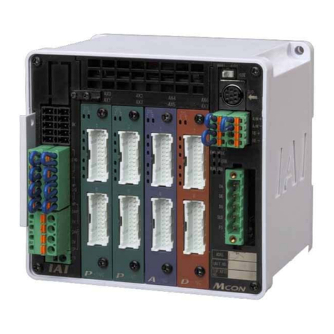
Manual No.: ME0266-8A
Other manuals for ASEP
3
This manual suits for next models
2
Table of contents
Other IAI Controllers manuals

IAI
IAI ROBO Cylinder RCP2 Series User manual

IAI
IAI SEL User manual

IAI
IAI RCD Series User manual

IAI
IAI SCON-CA User manual

IAI
IAI XSEL-P User manual

IAI
IAI PCON-CY User manual

IAI
IAI ACON-C User manual

IAI
IAI ELECYLINDER EC-WS10 R Series User manual

IAI
IAI X-SEL QX User manual

IAI
IAI ROBO Cylinder RA4C User manual

IAI
IAI ASEP User manual

IAI
IAI ELECYLINDER User manual

IAI
IAI ACON-C Series User manual

IAI
IAI X-SEL User manual

IAI
IAI X-SEL-J*-1-CC0 series User manual

IAI
IAI ROBO Cylinder RCP2 Series User manual

IAI
IAI EYECYLINDER EC-B6 Series User manual

IAI
IAI SCON-CA User manual

IAI
IAI RA3R User manual

IAI
IAI X-SEL User manual