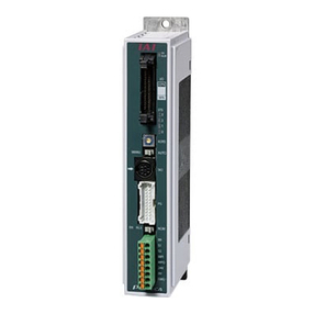
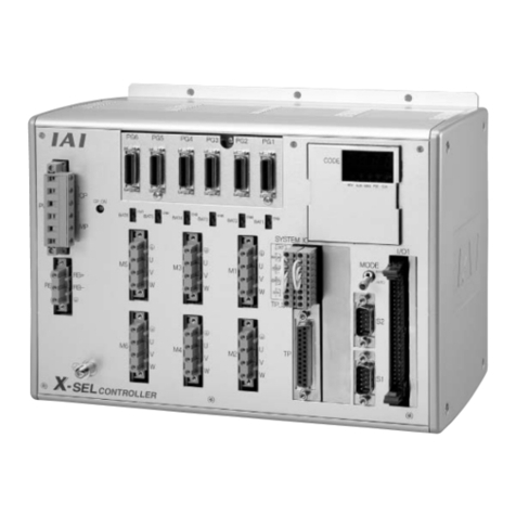
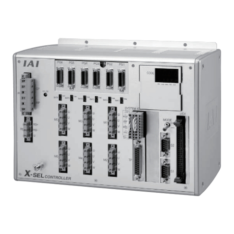
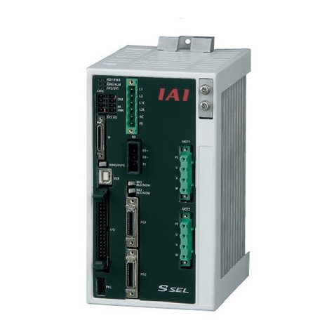
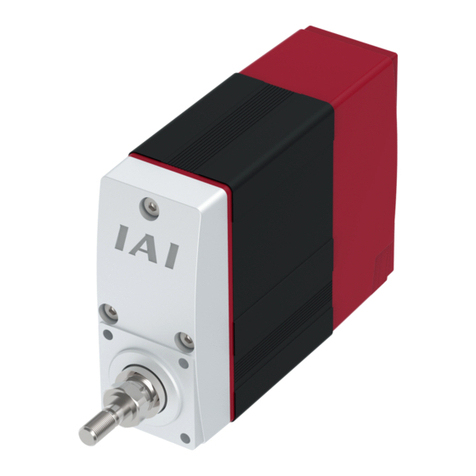
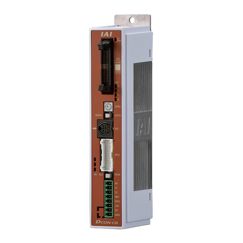
IAI X-SEL User manual

Operation Manual Fourth Edition
X-SEL Controlle
r
P/Q Type

CAUTION
Operator Alarm on Low Battery Voltage
This controller is equipped with the following backup batteries for retention of data in the event of power
failure:
[1] System-memory backup battery
For retention of position data, global variables/flags, error list, strings, etc.
[2] Absolute-encoder backup battery (optional)
For retention of rotation data (when an absolute encoder is used)
Since these batteries are not rechargeable, they will be eventually consumed. Unless the batteries are
replaced in a timely manner, the voltage will drop to a level where the data can no longer be retained. If a
power failure occurs in this condition, the data will be lost. (The life of each battery varies depending on
the operating time.)
Once the data is lost, the controller will not operate normally the next time the power is turned on, and
recovery will take time.
(Reference)
System-memory backup battery --- An alarm occurs when the voltage drops to approx. 2.6 V and data
backup becomes no longer possible at a battery voltage of approx.
2.3 V (rated voltage: 3.0 V).
Absolute-encoder backup battery --- An alarm occurs when the voltage drops to approx. 3.2 V and data
backup becomes no longer possible at a battery voltage of approx.
2.7 V (rated voltage: 3.6 V).
To prevent this problem, this controller can output a low battery voltage alarm from its I/O port.
To output this alarm signal from an I/O port, you must set the applicable I/O parameter.
•Alarm output for the system-memory backup battery
Set I/O parameter No. 59 to “1” --- Output port No. 313 (*) will be assigned as a dedicated port.
•Alarm output for the absolute-encoder backup battery
Set I/O parameter No. 60 to “1” --- Output port No. 314 (*) will be assigned as a dedicated port.
(*) Once set as an alarm output port, the applicable port can no longer be used as a general-
purpose port.
It is recommended that this function be utilized to prevent unnecessary problems resulting from low
battery voltage (consumption of battery life).
In particular, the person in charge of system design should utilize this function to provide a design means
for issuing an operator alarm using an output signal from an I/O port, while the person in charge of
electrical design should provide an electrical means for achieving the same effect.
For the battery replacement procedure, refer to the applicable section in the operating manual.
It is recommended that you always backup the latest data to a PC in case of voltage drop in the system-
memory battery or unexpected controller failure.
About teaching pendant and PC software
Q type controllers only support the following teaching pendant and PC software:
Teaching pendant: IA-T-XA (ANSI type)
PC software: IA-101-XA-MW (Supplied with category 4 cable)

CAUTION
Drive-Source Cutoff Relay Error (Detection of Fused Relay:
E6D)
As a condition limited to X-SEL-P type controllers of standard single-phase specification, a “drive-source
cutoff relay error (E6D)” may generate if the power is turned off and then turned on again (reconnected)
too quickly. This error indicates that the internal relay has fused, and its occurrence has to do with the
specific circuit configuration of the above controller type.
Although the specific wait time varies depending on the input voltage and number of external regenerative
resistors connected, as a general guide wait for at least 40 seconds before reconnecting the power.

INTELLIGENT ACTUATOR
Safety Precautions
Please read the information in “Safety Precautions” carefully before selecting a model and using the
product.
The precautions described below are designed to help you use the product safely and avoid bodily injury
and/or property damage.
Directions are classified as “danger,” “warning,” “caution” and “note,” according to the degree of
risk.
Danger Failure to observe the instruction will result in an imminent danger leading to
death or serious injury.
Warning Failure to observe the instruction may result in death or serious injury.
Caution Failure to observe the instruction may result in injury or property damage.
Note The user should take heed of this information to ensure the proper use of the
product, although failure to do so will not result in injury.
This product has been designed and manufactured as a component for use in general industrial
machinery.
Devices must be selected and handled by a system designer, personnel in charge of the actual operation
using the product or similar individual with sufficient knowledge and experience, who has read both the
catalog and operation manual (particularly the “Safety Precautions” section). Mishandling of the product
poses a risk.
Please read the operation manuals for all devices, including the main unit and controller.
It is the user’s responsibility to verify and determine the compatibility of this product with the user’s
system, and to use them properly.
After reading the catalog, operation manual and other materials, be sure to keep them in a convenient
place easily accessible to the personnel using this product.
When transferring or loaning this product to a third party, be sure to attach the catalog, operation manual
and other materials in a conspicuous location on the product, so that the new owner or user can
understand its safe and proper use.
The danger, warning and caution directions in this “Safety Precautions” do not cover every possible case.
Please read the catalog and operation manual for the given device, particularly for descriptions unique to
it, to ensure its safe and proper handling.
Danger
[General]
zDo not use this product for the following applications:
1. Medical equipment used to maintain, control or otherwise affect human life or physical health
2. Mechanisms and machinery designed for the purpose of moving or transporting people
3. Important safety parts of machinery
This product has not been planned or designed for applications requiring high levels of safety. Use of
this product in such applications may jeopardize the safety of human life. The warranty covers only the
product as it is delivered.

INTELLIGENT ACTUATOR
[Installation]
zDo not use this product in a place exposed to ignitable, inflammable or explosive substances. The
product may ignite, burn or explode.
zAvoid using the product in a place where the main unit or controller may come in contact with water or
oil droplets.
zNever cut and/or reconnect the cables supplied with the product for the purpose of extending or
shortening the cable length. Doing so may result in fire.
[Operation]
zIf you are using a pace maker or other mechanical implant, do not come within one meter of the
product. The strong magnetic field generated by the product may cause the pace maker, etc., to
malfunction.
zDo not pour water onto the product. Spraying water over the product, washing it with water or using it
in water may cause the product to malfunction, resulting in injury, electric shock, fire, etc.
[Maintenance, Inspection, Repair]
zNever modify the product. Unauthorized modification may cause the product to malfunction, resulting in
injury, electric shock, fire, etc.
zDo not disassemble and reassemble the components relating to the basic structure of the product or its
performance and function. Doing so may result in injury, electric shock, fire, etc.
Warning
[General]
zDo not use the product outside the specifications. Using the product outside the specifications may
cause it to fail, stop functioning or sustain damage. It may also significantly reduce the service life of
the product. In particular, observe the maximum loading capacity and speed.
[Installation]
zIf the machine will stop in the case of system problem such as emergency stop or power failure, design
a safety circuit or other device that will prevent equipment damage or injury.
zBe sure to provide Class D grounding for the controller and actuator (formerly Class 3 grounding:
Grounding resistance at 100 Ωor less). Leakage current may cause electric shock or malfunction.
zBefore supplying power to and operating the product, always check the operation area of the
equipment to ensure safety. Supplying power to the product carelessly may cause electric shock or
injury due to contact with the moving parts.
zWire the product correctly by referring to the operation manual. Securely connect the cables and
connectors so that they will not be disconnected or come loose. Failure to do so may cause the
product to malfunction or cause fire.
[Operation]
zDo not touch the terminal block or various switches while the power is supplied to the product. Failure
to observe this instruction may result in electric shock or malfunction.
zBefore operating the moving parts of the product by hand (for the purpose of manual positioning, etc.),
confirm that the servo is turned off (using the teaching pendant). Failure to observe this instruction may
result in injury.
zThe cables supplied with the product are flexible, but they are not robot cables. Do not store the cables
in a movable cable duct (cable bearer, etc.) that bends more than the specified bending radius.
zDo not scratch the cables. Scratching, forcibly bending, pulling, winding, crushing with heavy object or
pinching a cable may cause it to leak current or lose continuity, resulting in fire, electric shock,
malfunction, etc.

INTELLIGENT ACTUATOR
zIf the product is generating heat, smoke or a strange smell, turn off the power immediately. Continuing
to use the product may result in product damage or fire.
zIf any of the internal protective devices (alarms) of the product has actuated, turn off the power
immediately. Continuing to use the product may result in product damage or injury due to malfunction.
Once the power supply is cut off, investigate and remove the cause and then turn on the power again.
zIf the LEDs on the product do not illuminate after turning on the power, turn off the power immediately.
The protective device (fuse, etc.) on the live side may remain active. Request repair to the IAI sales
office from which you purchased the product.
[Maintenance, Inspection, Repair]
zBefore conducting maintenance/inspection, parts replacement or other operations on the product,
completely shut down the power supply. At this time, take the following measures:
1. Display a sign that reads, “WORK IN PROGRESS. DO NOT TURN ON POWER” at a conspicuous
place, in order to prevent a person other than the operator from accidentally turning on the power
while the operation is working.
2. When two or more operators are to perform maintenance/inspection together, always call out every
time the power is turned on/off or an axis is moved in order to ensure safety.
[Disposal]
zDo not throw the product into fire. The product may burst or generate toxic gases.
Caution
[Installation]
zDo not use the product under direct sunlight (UV ray), in a place exposed to dust, salt or iron powder,
in a humid place, or in an atmosphere of organic solvent, phosphate-ester machine oil, sulfur dioxide
gas, chlorine gas, acids, etc. The product may lose its function over a short period of time, or exhibit a
sudden drop in performance or its service life may be significantly reduced.
zDo not use the product in an atmosphere of corrosive gases (sulfuric acid or hydrochloric acid),
inflammable gases or ignitable liquids. Rust may form and reduce the structural strength or the motor
may ignite or explode.
zWhen using the product in any of the places specified below, provide a sufficient shield. Failure to do
so may result in malfunction:
1. Place where large current or high magnetic field is present
2. Place where welding or other operations are performed that cause arc discharge
3. Place subject to electrostatic noise
4. Place with potential exposure to radiation
zInstall the main unit and controller in a place subject to as little dust as possible. Installing them in a
dusty place may result in malfunction.
zDo not install the product in a place subject to large vibration or impact (4.9 m/s2 or more). Doing so
may result in the malfunctioning of the product.
zProvide an emergency-stop device in a readily accessible position so the device can be actuated
immediately upon occurrence of a dangerous situation during operation. Lack of such device in an
appropriate position may result in injury.
zProvide sufficient maintenance space when installing the product. Routine inspection and maintenance
cannot be performed without sufficient space, which will eventually cause the equipment to stop or the
product to sustain damage.
zDo not hold the moving parts of the product or its cables during installation. It may result in injury.
zAlways use IAI’s genuine cables for connection between the controller and the actuator. Also use IAI’s
genuine products for the key component units such as the actuator, controller and teaching pendant.

INTELLIGENT ACTUATOR
zBefore installing or adjusting the product or performing other operations on the product, display a sign
that reads, “WORK IN PROGRESS. DO NOT TURN ON POWER.” If the power is turned on
inadvertently, injury may result due to electric shock or sudden activation of an actuator.
[Operation]
zTurn on the power to individual equipment one by one, starting from the equipment at the highest level
in the system hierarchy. Failure to do so may cause the product to start suddenly, resulting in injury or
product damage.
zDo not insert a finger or object in the openings in the product. It may cause fire, electric shock or injury.
zDo not bring a floppy disk or other magnetic media within one meter of the product. The magnetic field
generated by the magnet may destroy the data in the floppy disk, etc.
[Maintenance, Inspection, Repair]
zWhen the power was turned off and the cover was opened to replace the battery, etc., do not touch the
condenser terminal in the product immediately after the power was turned off (within 30 seconds).
Residual voltage may cause electric shock.
zDo not touch the terminals when performing an insulation resistance test. Electric shock may result.
(Do not perform any withstand voltage test, since the product uses DC voltage.)
Note
[General]
zIf you are planning to use the product under a condition or environment not specified in the catalogs
and operation manual, or in an application requiring strict safety such as aircraft facility, combustion
system, entertainment machine, safety device or other equipment having significant impact on human
life or property, design operating ranges with sufficient margins from the ratings and design
specifications or provide sufficient safety measures such as fail-safes. Whatever you do, always
consult IAI’s sales representative.
[Installation]
zDo not place objects around the controller that will block airflows. Insufficient ventilation may damage
the controller.
zDo not configure a control circuit that will cause the load to drop in case of power failure. Configure a
control circuit that will prevent the table or load from dropping when the power to the machine is cut off
or an emergency stop is actuated.
[Installation, Operation, Maintenance]
zWhen handling the product, wear protective gloves, protective goggles, safety shoes or other
necessary gear to ensure safety.
[Disposal]
zWhen the product becomes no longer usable or necessary, dispose of it properly as an industrial
waste.
Others
IAI shall not be liable whatsoever for any loss or damage arising from a failure to observe the items
specified in “Safety Precautions.”

INTELLIGENT ACTUATOR
CE Mark
1. EC Directives
The EC Directives are a new set of directives issued by the European Commission that are intended to
protect the health and safety of users and consumers of products distributed within the EU (European
Union) zone, while ensuring free movements of these products within the EU zone. Companies exporting
to Europe or having a production facility in Europe must comply with the following directives in order to
receive a CE Mark certification for their products.
(1) Low-voltage Directive
The X-SEL-P/Q controllers are designed to comply with the Low-voltage Directive on their own.
(2) EMC Directives
The EMC Directives must be met by the entire equipment, or a combination of IAI’s controller and
other control devices and electrical components used by the equipment. IAI’s approach is to
determine representative connection/installation models (conditions), each combining controller(s),
actuator(s) and peripheral(s), and ensure that each of these models complies with the EMC
Directives. (Refer to 3, “Peripheral Configurations.”)
2. Applicable Standards
<Low-voltage Directive>
EN50178 (Electronic equipment used in electrical installations)
<EMC Directives>
EN55011 (Radio interference characteristics of industrial, scientific and medical equipment
generating radio frequency)
EN61000-6-2 (Immunity in industrial environment)
EN61000-4-2 (Immunity to electrostatic discharge)
EN61000-4-3 (Immunity to electromagnetic field generated by irradiated radio frequency)
EN61000-4-4 (Electrical first transient/burst immunity test)
EN61000-4-5 (Surge immunity test)
EN61000-4-6 (Immunity test against conductive interference induced by radio-frequency
electromagnetic field)
EN61000-4-8 (Immunity test against power-frequency magnetic field)
EN61000-4-11 (Immunity test against voltage dip, momentary power failure and voltage
fluctuation)

INTELLIGENT ACTUATOR
3. Peripheral Configurations
Three-phase power supply specification
P Type
(Standard Specification)
Q Type
(Global Specification)
200-VAC
three-
phase
power bus
Control panel
Circuit
breaker Earth
leakage
breaker
Surge
protector
Three-
phase
noise
filter
Ring
core Clamp
filters
Encoder cable
Motor cable Actuator
Controller
System
I/Os
Brake 24-VDC
power
supply
Emergency
stop switch
Encoder cable
Motor cable Actuator
Electro-
magnetic
contactor
Safety
relay
Safety circuit
200-VAC
three-
phase
power bus
Control panel
Circuit
breaker Earth
leakage
breaker
Surge
protector
Three-
phase
noise
filter
Ring
core Clamp
filters
Controller
System
I/Os
Brake 24-VDC
power
supply
Emergency
stop switch

INTELLIGENT ACTUATOR
Single-phase power supply specification
P Type
(Standard Specification)
Q Type
(Global Specification)
200-VAC
single-
phase
power bus
Control panel
Circuit
breaker Earth
leakage
breaker
Surge
protector
Single-
phase
noise
filter
Ring
core Clamp
filters
Encoder cable
Motor cable Actuator
Controller
System
I/Os
Brake 24-VDC
power
supply
Emergency
stop switch
Encoder cable
Motor cable Actuator
Electro-
magnetic
contactor
Safety
relay
Safety circuit
200-VAC
single-
phase
power bus
Control panel
Circuit
breaker Earth
leakage
breaker
Surge
protector
Single-
phase
noise
filter
Ring
core Clamp
filters
Controller
System
I/Os
Brake 24-VDC
power
supply
Emergency
stop switch

INTELLIGENT ACTUATOR
(1) Environment
Use your X-SEL-P/Q controller in an environment conforming to pollution degree 2 or 1 as specified
in IEC 60664-1.
Example) Install the controller in a control panel having a structure resistant to intrusion of water,
oil, carbon, dust, etc (IP54).
(2) Power Source
A) Use the controller in an environment conforming to overvoltage category II as specified in IEC
60664-1. To meet this requirement, be sure to install a circuit breaker between the distribution
board and the X-SEL controller.
B) If the I/O power or electromagnetic brake power is supplied externally, use a 24-VDC power
supply bearing a CE Mark.
(3) Grounding
To prevent electric shock, be sure to connect the FG terminal of the X-SEL-P/Q controller and the
protective grounding terminal (grounding plate) of the control panel.
(4) Earth Leakage Breaker
Install an earth leakage breaker (residual current device, or RCD) on the primary side of the X-SEL-
P/Q controller.

INTELLIGENT ACTUATOR
(5) Three-phase Noise Filter
Install a noise filter in the three-phase AC power line.
Supplier: Densei-Lambda
Model: MC1320
[Fig. 1] External View of Noise Filter (Three-phase Specification)
(6) Single-phase noise filter
Install a noise filter in the single-phase AC power supply line.
Manufacturer: Densei Lambda K.K.
Model: MXB-1220-33
[Fig. 2] External View of Noise Filter (Single-phase Specification)
Grounding
terminal
1: Input terminal 4:Output terminal
2: Input terminal 5:Output terminal
3: Input terminal 6:Output terminal
:Grounding terminal

INTELLIGENT ACTUATOR
(7) Ring Core
Install a ring core on the secondary side of the noise filter.
Supplier: NEC Tokin
Model: ESD-R-25
[Fig. 3] External View of Ring Core
Shape/Dimensions
ESD-R Series

INTELLIGENT ACTUATOR
(8) Clamp Filter A
Install the following noise filter to the control power AC cable and motor cable (if there are multiple
axes, connect to the cables of all axes).
Supplier: TDK
Model: ZCAT3035-1330
[Fig. 4] External View of Clamp Filter
(9) Clamp Filter B
Install the following noise filter to the motor power AC cable.
Supplier: Kitagawa Industries
Model: RFC-H13
[Fig. 5] External View of Clamp Filter
Shape/Dimensions
ZCAT Type

INTELLIGENT ACTUATOR
(10) Surge protector
Install a surge protector on the primary side of the noise filter.
Supplier: Okaya Electric Industries
Model: RxAxV-781BXZ-4 (three-phase)
RxAxV-781BWZ-4 (single-phase)
External Dimensions
[Fig. 6] External View of Surge Protector
Resin
Case
Lead wire

INTELLIGENT ACTUATOR
(11) Cables
The restrictions and cautions regarding the cables are summarized below.
A) All cables connected to the X-SEL-P/Q controller, such as the motor cable, encoder cable and
various network cables, must be kept to a length below 30 m.
B) For the brake power cable, use a shielded, 2-core (1-pair) twisted paired cable of AWG16 to 24
in wire size and connect the shield to ground on the 24-VDC power supply side.
C) For the system I/O cable connecting the safety relay unit with the X-SEL-Q controller, use a
shielded 9-pair twisted paired cable of AWG16 to 24 in wire size and connect the shield to
ground via an external safety circuit. No restrictions apply if an emergency stop switch is
connected directly to the X-SEL-P controller (where the cable has two cores).
D) If the controller is equipped with a CC-Link unit, use a 110-ΩCC-Link cable of Version 1.10
and install a clamp filter (ZCAT3035-1330) via two turns at a position near the cable connector
on the controller end.
1 turn 2 turns
E) If the controller is equipped with an Ethernet unit, install a clamp filter (ZCAT3035-1330) via
two turns at a position near the controller-end connector of the LAN cable (UTP twisted cable
conforming to category 5).

INTELLIGENT ACTUATOR
Prohibited Handling of Cables
Caution
When designing an application system using actuators and controllers, incorrect wiring or connection of
each cable may cause unexpected problems such as a disconnected cable or poor contact, or even a
runaway system. This section explains prohibited handling of cables. Read the information carefully to
connect the cables properly.
Ten Rules for Handling Cables (Must be Observed!)
1. Do not let the cable flex at a single point.
2. Do not let the cable bend, kink or twist.
3. Do not pull the cable with a strong force.
4. Do not let the cable receive a turning force at a
single point.
6. Do not pinch, drop a heavy object onto or cut the
cable.
5. When fixing the cable, provide a moderate slack
and do not tension it too tight.
Steel band
(piano wire)
Bundle loosely.
Use a curly
cable.
Do not use a spiral tube where
the cable flexes frequently.

INTELLIGENT ACTUATOR
7. Do not let the cable get tangled or kinked in a cable bearer or flexible tube. When bundling the cable,
keep a certain degree of flexibility (so that the cable will not become too taut when bent).
8. Do not cause the cables to occupy more than
60% of the space in the cable bearer.
9. Do not lay signal lines together with circuit lines
that create a strong electric field.
10. Always use a robot cable if the cable is likely to flex significantly.
[Standard structure of cable]
The standard structure of
cable will vary depending on
the manufacturer and type of
cable.
ÌNeed for Robot Cables
A cable connected to a moving part of an actuator system will inevitably receive repeated bending loads at
the base of the cable. As a result, the cores in the cable may break over time. To minimize the risk of
cable breakage, we strongly recommend that a robot cable offering significantly higher flexibility be used
in this type of application.
Cable
Cable bearer
Power line
Signal lines (flat cable) Duct
Absorbing material (When the
cable is bent, this material is
crushed by the surrounding signal
lines to maintain the shape of the
signal lines.)
Cover
Shield
Protective layer
Signal line (copper + tin)

INTELLIGENT ACTUATOR
Before Use
Caution
Caution
1. Be sure to read this operation manual to ensure the proper use of this product.
2. Unauthorized use or reproduction of a part or all of this operation manual is prohibited.
3. Always handle or operate the product in manners specified in this operation manual, by assuming that
whatever is not specified herein is not feasible. The warranty does not cover any defect arising from a
handling or operation not specified in this operation manual.
4. The information contained in this operation manual is subject to change without notice for the purpose
of modification and improvement.
* If you have purchased PC software:
Always back up the parameters after installing the product or changing the parameter settings.
5. The specifications in this manual may not apply to a custom product.
Caution
Action to Be Taken in Case of Emergency
If this product is found to be in a dangerous condition, immediately turn off all power switches of the
main unit and connected equipment or immediately disconnect all power cables from the outlets.
(“Dangerous condition” refers to a situation where the product is generating abnormal heat or smoke or
has ignited and a fire or danger to human health is anticipated.)

INTELLIGENT ACTUATOR
Table of Contents
Table of Contents
Introduction...................................................................................................1
Part 1 Installation .......................................................................................3
Chapter 1 Safety Precautions..............................................................................................................3
Chapter 2 Warranty Period and Scope of Warranty............................................................................ 4
1. Warranty Period........................................................................................................................ 4
2. Scope of Warranty .................................................................................................................... 4
3. Scope of Service....................................................................................................................... 4
Chapter 3 Installation Environment and Selection of Auxiliary Power Devices................................... 5
1. Installation Environment............................................................................................................ 5
2. Heat Radiation and Installation................................................................................................. 6
3. Selection of Auxiliary Power Devices........................................................................................ 7
4. Noise Control Measures and Grounding ................................................................................ 12
Chapter 4 Name and Function of Each Part...................................................................................... 15
1. Front View of Controller.......................................................................................................... 15
2. Explanation of Codes Displayed on the Panel Window.......................................................... 28
2.1 Application .................................................................................................................... 28
2.2 Core.............................................................................................................................. 29
2.3 Current Monitor and Variable Monitor........................................................................... 30
Chapter 5 Specifications.................................................................................................................... 32
1. Controller Specifications ......................................................................................................... 32
2. External I/O Specifications...................................................................................................... 36
2.1. NPN Specification......................................................................................................... 36
2.2. PNP Specification......................................................................................................... 38
3. Power-Source Capacity and Heat Output............................................................................... 40
4. External Dimensions............................................................................................................... 43
Chapter 6 Safety Circuit..................................................................................................................... 51
1. Items to Notes......................................................................................................................... 51
2. Safety Circuit for P Type (Standard Specification) Controller ................................................. 52
3. Safety Circuit for Q Type (Global Specification) Controller..................................................... 54
Chapter 7 System Setup....................................................................................................................59
1. Connection Method of Controller and Actuator....................................................................... 59
2. I/O Connection Diagram ......................................................................................................... 62
3. Multi-point DIO Board ............................................................................................................. 65
Chapter 8 How to Perform An Absolute Encoder Reset (Absolute Specification)............................. 72
1. Preparation.............................................................................................................................. 72
2. Procedure................................................................................................................................ 72
Chapter 9 Maintenance .....................................................................................................................77
1. Inspection points..................................................................................................................... 77
2. Spare consumable parts ......................................................................................................... 77
3. Replacement Procedure for System-Memory Backup Battery............................................... 78
4. Replacement Procedure for Absolute-Data Backup Battery................................................... 81
Other manuals for X-SEL
5
Table of contents
Other IAI Controllers manuals

IAI
IAI X-SEL QX User manual

IAI
IAI ROBO Cylinder RCP2 Series User manual

IAI
IAI XSEL-P User manual

IAI
IAI RA Series User manual

IAI
IAI ROBO Cylinder RCS4-TA4C User manual

IAI
IAI SCON-CB-F User manual

IAI
IAI PCON-CB series User manual

IAI
IAI SCON-CA User manual

IAI
IAI ROBO Cylinder RCP2 Series User manual

IAI
IAI SEL User manual