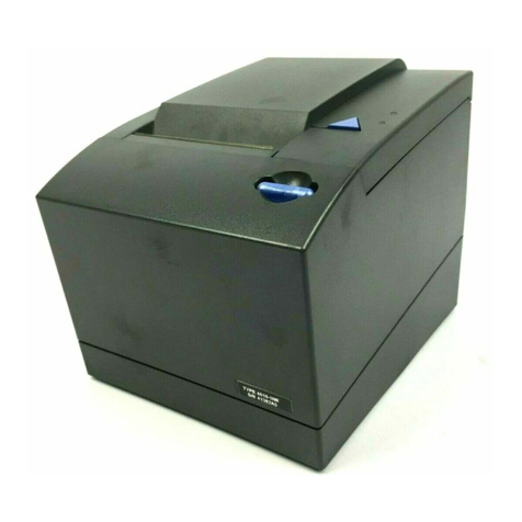
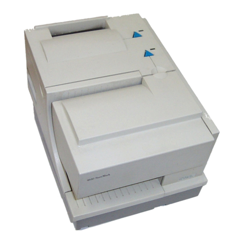
IBM SureMark 4610 User manual

4610 SureMark Three-Station Printer All Models
Hardware Service Manual
GY27-0399-03Updated August 13, 2003


4610 SureMark Three-Station Printer All Models
Hardware Service Manual
GY27-0399-03Updated August 13, 2003

Note
Before using this information and the product it supports, be sure to read “Safety information” on page xvii and the general
information under Appendix B, “Notices”, on page B-1.
Fourth Edition (June 2003)
This edition applies to the IBM 4610 SureMark Three-Station Point-of-Sale Printers, Models TNx, GRx, GBx and
GE3.
This publication is available on the IBM Retail Store Solutions Electronic Web site.
1. Go to www.ibm.com/solutions/retail/store.
2. Select Support (at the left on the main page of the Web site).
3. Select Publications to access IBM Retail Store Solutions Electronic Support Web site.
Order publications through your IBM representative or the IBM branch office serving your locality. Publications are
not stocked at the address given below.
A form for reader’s comments is also provided at the back of this publication. If the form has been removed, address
your comments to:
IBM Corporation,
Information Development, Department CJMA
PO Box 12195
Research Triangle Park, North Carolina, 27709 U.S.A.
When you send information to IBM, you grant IBM a nonexclusive right to use or distribute whatever information you
supply in any way it believes appropriate without incurring any obligation to you.
© Copyright International Business Machines Corporation 2001, 2003. All rights reserved.
US Government Users Restricted Rights – Use, duplication or disclosure restricted by GSA ADP Schedule Contract
with IBM Corp.
Updated August 13, 2003
|
|
|
|
|
|
|
|
|
|
|
|
|
|
|
|
|

Contents
Figures ............................v
Tables ............................ix
Preface ............................xi
Who should read this manual ....................xi
Prerequisites to this manual ....................xi
How this manual is organized ....................xi
Related publications and diskettes ..................xi
Summary of changes ......................xiii
June 2003 ..........................xiii
October 2002 .........................xiii
May 2002 ...........................xiii
December 2001 ........................xiii
August 2001..........................xiii
Tell us what you think......................xv
Safety information.......................xvii
Chapter 1. Introduction .....................1-1
Available model designations ...................1-1
Printer overview ........................1-5
Communications overview ....................1-6
Physical requirements ......................1-9
Software requirements .....................1-11
Miscellaneous information ....................1-12
Limitations ..........................1-13
User responsibilities ......................1-13
Chapter 2. Installation, service, and utility software adjustments .....2-1
4610 diskette download support information ..............2-1
Software adjustments for document insert station ............2-1
4610 fonts and logos utility diskette (Models TNx only) ..........2-4
Firmware update (Models TNx only) .................2-4
Emulating the IBM Model 3 or Model 4 printers (Models TNx only) .....2-6
MICR data parser sample code (Model TN4 only) ............2-7
Chapter 3. Problem determination for the 4610 Three-Station Printer ...3-1
Fiscal unit return codes .....................3-1
Offline tests ..........................3-1
Symptoms ..........................3-6
Chapter 4. FRU removal and replacement ..............4-1
Top covers procedures (Models TNx) ................4-2
Document insert station procedures (Models with DI only) .........4-9
Logic cards procedure .....................4-43
Customer receipt station procedures ................4-49
Journal station procedures ....................4-71
Interface Card Assembly Procedures ................4-81
Chapter 5. Hardware adjustment procedures ............5-1
Updated August 13, 2003
© Copyright IBM Corp. 2001, 2003 iii
||

Electrostatic discharge (ESD) ...................5-1
Mechanical adjustments .....................5-2
Chapter 6. Operation ......................6-1
Indicators, controls, and stations – thermal/impact printers ........6-1
Check verification and printing (model TN4 only) ............6-2
Ribbon loading (Models with DI) ..................6-6
Clearing jams in the check flipper area ................6-8
Cleaning the MICR reader read head ................6-10
Thermal printheads cleaning ...................6-11
Chapter 7. Parts listing .....................7-1
Assembly 1: Printer assembly ...................7-2
Assembly 2: Journal station cover and button assembly .........7-4
Assembly 3: Customer receipt station operator button assembly ......7-6
Assembly 4: Logic cards and shock mounts ..............7-8
Assembly 5: Document insert station ................7-10
Assembly 6: Customer receipt thermal printhead assembly and cover ....7-12
Assembly 7: Printhead transport and ribbon drive assembly........7-14
Assembly 8: Impact printhead assembly ...............7-16
Assembly 9: Document insert station platen and lever ..........7-18
Assembly 10: Document insert drive shaft assembly ..........7-20
Assembly 11: Document insert station gears and motor .........7-22
Assembly 12: Customer receipt drive, cutter, and platen .........7-24
Assembly 13: Models TN3, TN4, and TN5 interface assembly .......7-26
Assembly 14: Model GRx (RS-485) fiscal interface assembly .......7-28
Assembly 15: Model GBx and GEx (USB) fiscal interface assembly .....7-30
Assembly 16: Journal assembly — both sides view ...........7-32
Assembly 17: Models GR3 and GE3 power supply assembly (Argentina only) 7-34
Assembly 18: Hardware Kits ...................7-36
Assembly 19: Cable assemblies, filler panel, power supply ........7-37
Assembly 20: Complete printer replacement as a FRU .........7-38
Assembly 21: Paper roll holder, (Argentina only) ............7-40
Appendix A. Removal and replacements for Argentina Model GR3 and
GE3 printers ........................A-1
Remove the paper roll holder ...................A-1
Remove the security shield ....................A-3
Remove the interface assembly ..................A-5
Remove the power switch and/or cable ...............A-7
Logic card procedures .....................A-10
Remove the power cable ....................A-13
Remove the power supply ....................A-14
Appendix B. Notices ......................B-1
Trademarks..........................B-2
Electronic emission notices ....................B-3
Japanese voluntary control council for interference (VCCI) statement ....B-4
Taiwanese class A warning statement ................B-5
Korean communications statement .................B-5
Electrostatic discharge (ESD) ...................B-5
Part Number Index ......................C-1
Index ............................X-1
Updated August 13, 2003
iv Three Station Printer: Service
||

Figures
1-1. IBM 4610 SureMark point-of-sale printer.....................1-5
1-2. Cable Connectors and RS-232 Mode Switch for Thermal/Impact SureMark Printers 1-7
1-3. SureMark Printer Dimensions ........................1-10
2-1. Adjustment and Alignment Printouts ......................2-3
3-1. Offline Printer Test Pattern (Thermal/Impact SureMark Printers) ............3-3
3-2. MICR Reader Test Results – Good Noise Level ..................3-4
3-3. MICR Reader Test Results – Noise Level Needs Adjusting ..............3-5
4-1. Removing the Paper and Ribbon Covers ....................4-4
4-2. Release the Rear Latch Tabs .........................4-5
4-3. Mounting Posts on Front Face of Cover .....................4-5
4-4. Removing the Top Cover ..........................4-6
4-5. Removing the operator buttons in the top cover ..................4-8
4-6. Removing the Document Insert Feed Cover and the Flipper Cartridge ..........4-9
4-7. Replacing the Printhead ..........................4-10
4-8. Disconnecting the Home Sensor .......................4-11
4-9. Replacing the Home Sensor.........................4-12
4-10. Removing the Ribbon Drive Assembly .....................4-14
4-11. Removing the Tensioner ..........................4-15
4-12. Removing the Timing Belt..........................4-17
4-13. Removing the Printhead/Home Sensor Cable ..................4-17
4-14. Removing the Carriage Assembly, Front or Rear Transport Shafts ...........4-18
4-15. Removing the Front Transport Carrier Bearing ..................4-19
4-16. Removing the Transport Motor ........................4-21
4-17. Disconnecting the Printhead Cable and Home Sensor ...............4-23
4-18. Disconnecting the Sensor Spring and Removing the DI Insert Assembly ........4-25
4-19. Removing the Document Insert Platen Assembly .................4-27
4-20. Removing the Front Shock Mount.......................4-29
4-21. Removing the MICR............................4-29
4-22. Disconnecting the MICR Cable........................4-31
4-23. Removing the Lower Forms Entry Frame ....................4-32
4-24. Removing the Flipper Assembly .......................4-32
4-25. Removing the Bail ............................4-33
4-26. Removing the DI Backup Roller .......................4-35
4-27. Removing the DI Lever Assembly .......................4-36
4-28. Removing the Front Shock Mount and Disconnecting the MICR Cable .........4-38
4-29. Gear Removal ..............................4-38
4-30. Removing the Document Insert Feed Roller ...................4-39
4-31. Removing the Front Shock Mount and Disconnecting the MICR Cable .........4-40
4-32. Removing the Motor Gear and Idler Gear ....................4-41
4-33. Removing the Document Insert Feed Motor ...................4-41
4-34. Removing the Switch Card and Printhead Spacer .................4-42
4-35. Removing the Interface Card Assembly.....................4-44
4-36. Printhead cable .............................4-45
4-37. Main logic cable connectors .........................4-46
4-38. Main logic cable connectors .........................4-47
4-39. Removing the receipt and ribbon covers ....................4-50
4-40. Removing the Thermal Cover ........................4-51
4-41. Removing the Spiral Wraps .........................4-52
4-42. Disconnecting the Thermal Printhead Cable from the Main Logic Card .........4-52
4-43. Thermal Printhead Latch Assembly ......................4-53
4-44. Removing the Thermal Printhead Latch Spring ..................4-54
4-45. View of Drag Strip from Back of Printer.....................4-55
4-46. Removing the Drag Strip ..........................4-56
Updated August 13, 2003
© Copyright IBM Corp. 2001, 2003 v

4-47. Thermal Printhead Assembly ........................4-58
4-48. Removing the Spiral Wraps .........................4-58
4-49. Removing the Cutter Stud, Stationary Blade, and Printhead Shaft (Model GR3 or TN3) 4-59
4-50. Removing the Cutter Stud, Stationary Blade, and Printhead Shaft (Model GR3 or TN4) 4-59
4-51. Removing the Thermal Platen Assembly ....................4-60
4-52. Removing the Customer Receipt Motor.....................4-63
4-53. Removing the Rotating Blade and Thermal Guide (Model GR3 or TN3) .........4-64
4-54. Removing the Rotating Blade and Thermal Guide (Model TN4) ............4-65
4-55. Removing the Cutter Gears .........................4-66
4-56. Removing the Customer Receipt Paper Guide ..................4-68
4-57. Removing the Front Shock Mount and Disconnecting the MICR Cable .........4-69
4-58. Customer Receipt Paper Bucket .......................4-70
4-59. Journal station — button ..........................4-71
4-60. Journal Station —Thermal Printhead Assembly ..................4-73
4-61. Journal Station —Thermal Printhead Cover Assembly ...............4-74
4-62. Journal Station — Platen Assembly ......................4-75
4-63. Journal Station — Motor Assembly ......................4-76
4-64. Journal Station — Motor Assembly ......................4-78
4-65. Journal Station — Gear Kit with Clutch and E-clip Assembly .............4-79
4-66. Journal Station — Top Cover Sensor switch Assembly ...............4-80
4-67. Remove Printer Seal and the Secure Screw from Rear Panel ............4-82
4-68. Loosen the Fiscal Interface Assembly Screw and Tilt and Remove Assembly .......4-83
4-69. Remove Processor Card ..........................4-84
4-70. Remove Interface Card from Assembly .....................4-85
4-71. Release the Rear Latch Tabs ........................4-89
4-72. Mounting Posts on Front Face of base Cover ..................4-90
5-1. DI forms adjustment ............................5-3
5-2. Placement of gap setting tool .........................5-5
5-3. Platen gap adjustment ...........................5-5
5-4. DI open lever adjustment ..........................5-6
5-5. Cutter blade run-In (Models TN3 and TN4) ....................5-7
5-6. Thermal printhead adjustment for customer receipt and journal stations .........5-9
5-7. Thermal paper switch adjustment .......................5-10
6-1. Indicators, controls, and printing stations – Thermal/Impact SureMark Printers .......6-1
6-2. Positioning checks and documents for reading and printing ..............6-3
6-3. Printable area of an inserted document (portrait)..................6-4
6-4. Printable area of an inserted document (landscape) ................6-5
6-5. Opening the ribbon cover ..........................6-6
6-6. Ribbon cartridge loading ..........................6-7
6-7. Ribbon path around the printhead .......................6-7
6-8. Removing the lower document insert (DI) cover ..................6-8
6-9. Removing the check flipper cartridge ......................6-9
6-10. Printhead and print line area.........................6-11
A-1. Distributed paper roll holder .........................A-1
A-2. Integrated paper roll holder .........................A-2
A-3. Removing the distributed paper roll holder ....................A-3
A-4. Remove the security shield .........................A-4
A-5. Security shield ..............................A-4
A-6. Remove the printer seal and the secure screw from rear panel ............A-6
A-7. Loosen the fiscal interface assembly screw and tilt the assembly to disconnect electrical
connector ................................A-6
A-8. Disconnect the electrical connectors and remove the assembly ............A-7
A-9. Location of the power on/off switch ......................A-8
A-10. Power switch and cable with bracket ......................A-9
A-11. Power cable beside main logic card ......................A-10
A-12. Removing the Printer Logic Cards ......................A-12
Updated August 13, 2003
vi Three Station Printer: Service
||


A-13. Removing the Interface Card Assembly ....................A-13
A-14. Loosen the screws and lower the power module cover assembly ...........A-14
A-15. Loosen the connectors and remove the power supply ...............A-15
A-16. Reassembly of the power module into the printer .................A-16
A-17. Complete the insertion of the interface assembly housing into the printer ........A-16
Updated August 13, 2003
Figures vii
||

Updated August 13, 2003
viii Three Station Printer: Service

Tables
1-1. SureMark Three-Station printer model numbers and the features............1-2
3-1. Printer Symptoms or Messages ........................3-6
4-1. Resistance Check ............................4-45
Updated August 13, 2003
© Copyright IBM Corp. 2001, 2003 ix
||

Updated August 13, 2003
xThree Station Printer: Service

Preface
This manual provides information about problem determination, testing,
field-replaceable unit (FRU) removal and replacement procedures, and parts listing
for the IBM 4610 SureMark
™
Three-Station Point-of-Sale Printers.
Who should read this manual
This manual is intended for use by trained service representatives.
Prerequisites to this manual
You should be familiar with the contents of the IBM 4610 SureMark Point-of-Sale
Printers: User’s Guide, GA27-4291
How this manual is organized
vChapter 1, “Introduction”, on page 1-1 provides an overview of the IBM SureMark
4610 Three-Station 4610 Printer.
vChapter 2, “Installation, service, and utility software adjustments”, on page 2-1
provides information on installation, service, and utility software.
vChapter 3, “Problem determination for the 4610 Three-Station Printer”, on page
3-1 provides information on testing, messages, and symptoms for determining
any failing components of the 4610 printer.
vChapter 4, “FRU removal and replacement”, on page 4-1 provides information
about procedures for removing and replacing printer components. provides
information about procedures for removing and replacing components specific to
the Model GR3 — fiscal printer.
vChapter 5, “Hardware adjustment procedures”, on page 5-1 provides information
about procedures for operation of the printer.
vChapter 6, “Operation”, on page 6-1 provides part numbers of the field
replaceable units (FRUs) for the SureMark printer.
vAppendix A, “Removal and replacements for Argentina Model GR3 and GE3
printers”, on page A-1 provides information about procedures for removing and
replacing the internal power supply for the Model GR3 printer for Argentina.
vAppendix B, “Notices”, on page B-1 contains electronic emission notices and
other general information.
v“Safety Information” on page 4-86 contains the lithium battery safety statement.
Related publications and diskettes
vIBM 4610 SureMark Point-of-Sale Printers: User’s Guide, GA27-4291
vIBM 4610 SureMark Point-of-Sale Printers Installation Utilities Diskette
vIBM 4694/4695 Point-of-Sale Terminals Service Diskette
vIBM Safety Information – Read This First, GA27-4004.
The service diskette materials are available only for download from the Internet.
Publications for the SureMark Three-Station Printer are available only by download
from the internet.
Updated August 13, 2003
© Copyright IBM Corp. 2001, 2003 xi

For information about ordering IBM publications not shipped with the 4610
SureMark Point-of-Sale Printers, contact your IBM representative or your place of
purchase.
Updated August 13, 2003
xii Three Station Printer: Service

Summary of changes
June 2003
Added/Changed part numbers in the parts catalog.
Modified table 1–1.
Updated various graphics.
October 2002
Added:
vNew SureMark Three-Station printer USB Models GB3, GB5 and GE3
information has been added.
vTable 1-1 on page 1-2 has been updated that shows the Printer Model Numbers
and the main characteristics of the models.
vUpdated Assembly 14 in parts listing.
May 2002
Added information for:
vThe printer for Greece and Turkey
vNew security shield for Argentina
vArgentina paper specification.
December 2001
Updates include:
Corrections to parts catalog
Model clarifications to chapter 1
Various minor changes throughout.
August 2001
Updates for Models TN3 and TN5 information and Models GR3 and GR5
information has been added.
A table has been added that shows the Printer Model Numbers and the main
characteristics of the various models.
Includes information about how to service the Argentine printer’s power supply.
Includes information about the utility service diskette and how to use it when you
change the main logic card on the DI-less model.
Updated August 13, 2003
© Copyright IBM Corp. 2001, 2003 xiii
|
|
|
|

Updated August 13, 2003
xiv Three Station Printer: Service

Tell us what you think
Your feedback is important in helping us to provide the most accurate and
high-quality information. Please take a few moments to tell us what you think about
this book. The only way for us to know if you are satisfied with our books, or how
we might improve their quality is through feedback from customers like you. If you
have any comments about this book, please fill out one of the forms at the back of
this book and return it by mail, by fax, or by giving it to an IBM representative. If
applicable, include a reference to the specific location of the text on which you are
commenting. For instance, include the page or table number. If you desire an
answer to a query, please include your name and either your address, FAX number,
or telephone number.
Between major revisions of this manual we may make minor technical updates. The
latest softcopy version of this manual is available under Publications on the IBM
Retail Store Solutions Web site.
Updated August 13, 2003
© Copyright IBM Corp. 2001, 2003 xv

Updated August 13, 2003
xvi Three Station Printer: Service

Safety information
Danger:
Before you begin to install this product, read the safety information in IBM
Safety Information — Read This First, GA27-4004. This booklet describes safe
procedures for cabling and plugging in electrical equipment.
Gevaar:
Voordat u begint met de installatie van dit produkt, moet u eerst de
veiligheidsinstructies lezen in de brochure Veiligheidsinstructies—Lees dit
eerst, GA27-4004. Hierin wordt beschreven hoe u electrische apparatuur op
een veilige manier moet bekabelen en aansluiten.
Perigo:
Antes de começar a instalar este produto, leia as informações de segurança
contidas em Informações Sobre Seguranaça—Leia Isto Primeiro, GA27-4004.
Esse folheto descreve procedimentos de segurança para a instalação de
cabos e conexões em equipamentos elétricos.
Updated August 13, 2003
© Copyright IBM Corp. 2001, 2003 xvii

Fare!
Før du installerer dette produkt, skal du læse sikkerhedsforskrifterne i
Sikkerhedsforskrifter—Lœs dette først GA27-4004. Vejledningen beskriver den
fremgangsmåde, du skal bruge ved tilslutning af kabler og udstyr.
Gevaar
Voordat u begint met het installeren van dit produkt, dient u eerst de
veiligheidsrichtlijnen te lezen die zijn vermeld in de publikatie IBM Safety
Information — Read This First, GA27-4004. In dit boekje vindt u veilige
procedures voor het aansluiten van elektrische appratuur.
VAARA
Ennen kuin aloitat tämän tuotteen asennuksen, lue julkaisussa
Turvaohjeet—Luetämä ensin, GA27-4004, olevat turvaohjeet. Tässä kirjasessa
on ohjeet siitä, miten sähkölaitteet kaapeloidaan ja kytketään turvallisesti.
Updated August 13, 2003
xviii Three Station Printer: Service
Table of contents
Other IBM Printer manuals

IBM
IBM V03 Setup guide

IBM
IBM 6400 Series User manual

IBM
IBM 4247 Setup guide

IBM
IBM 4400-006 - 4400 Model 006 B/W Direct Thermal User manual

IBM
IBM 6400 Series User manual

IBM
IBM 4230 - Model 4i3 B/W Dot-matrix Printer User manual

IBM
IBM Infoprint 21 Reference guide

IBM
IBM InfoPrint 1634 User manual

IBM
IBM 3160 Technical manual

IBM
IBM 5225 1 Manual

IBM
IBM 24 User manual

IBM
IBM 6400 Series Setup guide

IBM
IBM 3130 User manual

IBM
IBM 4019 User manual

IBM
IBM 4610 - Kxx Owner's manual

IBM
IBM SUREMARK 1NR User manual

IBM
IBM Infoprint Color 1354 Product information sheet

IBM
IBM 4247 - Model 001 B/W Dot-matrix Printer User manual

IBM
IBM 6400 Series User manual

IBM
IBM INFO PRINT 3000 Manual