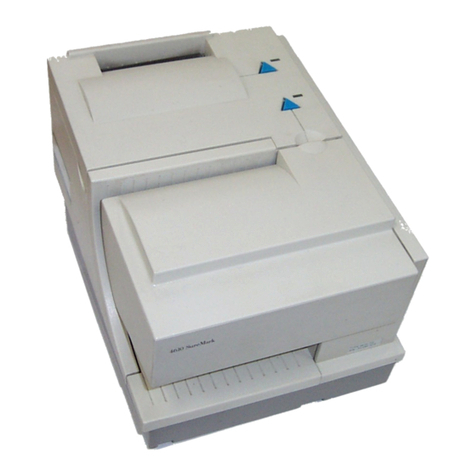
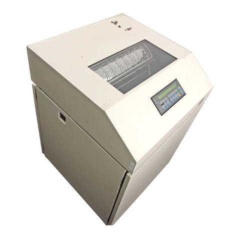
IBM 4247 Setup guide

4247 Printers
Maintenance Information
Document Number: SA24-4400-05
Part Number: 27P8450
IBM

Note!
Before using this information and the product it supports, read the information in “Safety
Information” on page 9.
Sixth Edition (February 2001)
This edition replaces SA24-4400-04. Requests for IBM
®
publications should be made to your IBM representative or to the IBM
branch office serving your locality. If you request publications from the address given below, your order will be delayed because
publications are not stocked there. Many of the IBM Printing Systems Division publications are available from the web page listed
below.
Internet
Visit our home page at: http://www.ibm.com/printers
A Reader’s Comments form is provided at the back of this publication. If the form has been removed, you can send comments by fax
IBM Printing Systems Division
Department H7FE Building 003G
Information Development
PO Box 1900
Boulder CO 80301-9191 USA
IBM may use or distribute whatever information you supply in any way it believes appropriate without incurring any obligation to you.
© Copyright International Business Machines Corporation 1995, 2001. All rights reserved.
US Government Users Restricted Rights – Use, duplication or disclosure restricted by GSA ADP Schedule Contract with IBM Corp.

Contents
Safety Information.................................................9
Safety Notices ...................................................9
General Safety ..................................................11
Electrical Safety ..................................................13
Pre-Service Inspection ..............................................15
Related Publications...............................................17
Model A00 Publications ..............................................17
Models 001 and 002 Publications .........................................17
Model 003 Publications ..............................................18
Common Publications ...............................................18
Preface - What’s New in the Model 003.....................................19
Chapter 1. Diagnosing Problems ........................................20
Maintenance Analysis Procedures (MAPs) ....................................20
Defining The Problem ..............................................20
MAP 0100: START OF CALL ...........................................23
MAP 0110: Automatic Sheet Feeder .......................................26
MAP 0120: Parallel or Serial Attachment, Model A00 and Model 003.......................33
MAP 0121: Parallel with Twinax or Coax Attachments, Models 001, 002, or 003 .................41
Attachment Card Procedure 1..........................................50
Attachment Card Procedure 2..........................................56
MAP 0122: Network Print Server Attachment ...................................59
MAP 0130: No Paper Movement .........................................62
MAP 0131: Paper Path Sensor ..........................................66
MAP 0140: Printhead Drive ............................................70
MAP 0150: Power Supply .............................................75
MAP 0160: Ribbon Feed and Ribbon Lift .....................................89
© Copyright IBM Corp. 1995, 2001 3

MAP 0170: ASF Stacker .............................................94
MAP 0180: Top Cover Interlock ..........................................98
MAP 0190: Form Feed Problems ........................................101
MAP 0200: 55 AFTA Errors ...........................................127
MAP 0210: Intermittent Failures .........................................130
MAPs Reference Tables .............................................133
Reference Table 1, Model A00 Error Messages ................................133
Reference Table 2, Models 001, 002, and 003 Error Messages ........................136
Reference Table 3, No Printed Characters...................................146
Reference Table 4, Print Quality Failures ...................................146
Reference Table 5, Operator Panel and Miscellaneous Problems .......................149
Reference Table 6, LED and Test Page Problems – NPS and LAN Attachment Card .............152
Reference Table 7, Network Server Problems – NPS and LAN Attachment Card ...............156
Reference Table 8, Power Supply Connector Pins and Voltages .......................156
Reference Table 9, Base Code Compatibilities ................................157
Reference Table 10, Ribbon Lift and 26–Pin Cable Connectors ........................158
Reference Table 11, Paper Paths .......................................158
Reference Table 12, Minimum Microcode ...................................158
Chapter 2. Diagnostics .............................................160
Test and Diagnostic Information - Model A00 ..................................160
How To Print the Print Test...........................................160
How To Print Firmware Part Number and Version Levels ...........................160
How To Print the Power On Configuration ...................................160
How To Print the Program Setup Configuration ................................161
How To Run the Test and Diagnostic (T&D) Programs ............................161
T&D Descriptions ...............................................164
T&D Error Messages and Actions .......................................190
Test and Diagnostic Information - Models 001, 002, and 003 ..........................197
How To Print the Printer Demonstration ....................................197
How To Print Firmware Part Number and Version Levels ...........................197
Contents 4


How to Print the Printer Configuration and the Custom Sets .........................198
How to Print and Clear the Error Log, and Print the Usage Metrics ......................198
How To Run the Test and Diagnostic (T&D) Programs ............................201
T&D Descriptions ...............................................204
T&D Error Messages and Actions – Models 001, 002, and 003 ........................231
Chapter 3. Circuit Diagrams ..........................................240
Wiring Diagrams .................................................240
Printhead and Motors Wiring Diagrams ....................................240
Cable Diagrams ................................................258
Attachment Connectors ............................................262
Chapter 4. Locations ..............................................265
Locations and Orientations............................................266
Logic Board Microcode Module Locations and Orientation - Model A00 ....................266
Logic Board Microcode Module Locations and Orientation - Models 001 and 002...............268
Attachment Card Microcode Module Location and Orientation - Models 001 and 002.............269
Microcode Module Label - Model A00 .....................................270
Microcode Module Label - Models 001 and 002 ................................270
Connector Locations - Early Model A00 ....................................271
Connector Locations - Later Model A00, and Models 001 and 002 ......................272
Connector Locations - Model 003 .......................................273
Network Print Server Attachment Pin 18 +5 V Jumper Location and the Parallel Connector .........273
Chapter 5. Removals and Adjustments ....................................275
Service Position .................................................275
275
Service Checks and Adjustments ........................................279
Carriage Drive Belt...............................................279
Carriage Support Shaft.............................................280
Paper Feed Belt ................................................281
Automatic Forms Thickness Adjustment (AFTA) ................................282
First Line Printing ...............................................294
Contents 5

Bidirectional Printing ..............................................294
Tear-Off Line ..................................................295
Sensor Service Checks ............................................296
Paper Path Service Checks ..........................................301
Automatic Sheet Feeder (ASF) Bins Service Check ..............................319
ASF Stacker Service Check ..........................................322
Platen Pinch Roller Assembly Service Check .................................323
Tractor Assembly Service Check........................................325
Ribbon Feed and Ribbon Lift Service Check..................................330
Printhead Drive Service Check.........................................333
Print Quality Checks ..............................................338
Removals/Replacements.............................................346
Overview....................................................346
Printer Covers .................................................347
Ribbon .....................................................353
Operator Panel.................................................355
Printhead....................................................356
Model 003 Attachment Cards: Serial, Twinax, LAN, Coax ...........................359
Attachment Card Guide Assembly with the Interposer Connector (Model 003) ................364
Logic Board - Model 003............................................366
Logic Board - Model A00............................................370
EMI Filter (Model A00 Early-Level Logic Board Only) .............................377
Logic Board - Models 001 and 002 ......................................378
Logic Board Component Inspection Reference ................................385
Serial Attachment Card - Model A00......................................390
Coax Attachment Card - Models 001, and 002 ................................392
Twinax Attachment Card - Models 001, and 002................................396
Power Supply .................................................400
Ribbon Drive Motor ..............................................403
Ribbon Lift Motor................................................405
Automatic Forms Thickness Adjust (AFTA) Assembly .............................407
Contents 6

Platen Pinch Roller Assembly .........................................411
Carriage Drive Motor Assembly ........................................415
Carriage Drive Belt...............................................420
Paper Bail Assembly ..............................................422
Manual Sheet Feed Tray............................................425
Upper Feed Roller Shaft Assembly ......................................426
Platen Assembly ................................................429
Printhead Mask ................................................432
Lower Feed Roller Assembly..........................................435
Carriage Assembly...............................................437
Carriage Support Shaft.............................................439
Sensor Cable Assembly ............................................441
Printer Mechanical Assembly .........................................444
Paper Feed Motor ...............................................447
Paper Feed Motor Drive Belt..........................................448
Lower Plastic Shield/Support Assembly ....................................451
Chapter 6. Parts Catalog ............................................457
How To Use This Parts Catalog .........................................457
Assemblies....................................................459
Assembly 1: Covers and Operator Panel ....................................460
Assembly 2: Tractor Assembly, Automatic Sheet Feeder, and Stacker......................463
Assembly 3: Printer Mechanical Assembly and Base ..............................465
Assembly 4: Mechanical Assembly I .......................................467
Assembly 5: Mechanical Assembly II.......................................470
Assembly 6: Mechanical Assembly III ......................................473
Assembly 7: Electronics I ............................................475
Assembly 8: Electronics II ............................................477
Assembly 9: Printhead and Cables .......................................479
Assembly 10: Power Cords, Parts Kits, and Tools ................................481
Chapter 7. Preventative Maintenance .....................................483
Contents 7

Appendix A. Printer Configuration.......................................484
Configuration Information — All Models .....................................484
Overview....................................................484
Model A00 Configuration Information .....................................485
Models 001, 002, and 003 Configuration Information .............................499
Appendix B. Supplies, Forms, Paths, & Environmental Considerations ..................531
Overview.....................................................531
Supplies .....................................................531
Choosing a Forms Path for Your Needs .....................................531
Choosing a Forms Path for Special Forms ...................................532
Other Considerations for Forms .........................................533
Forms and Paper Specifications ........................................534
Forms Stacking Recommendations .......................................539
Forms Stack Input and Output Locations ....................................540
Forms Paths ..................................................541
Environmental Requirements ..........................................546
Operating Environment.............................................546
Nonoperating Environment...........................................547
Shipping Environment .............................................547
Storage Environment..............................................548
Appendix C. Flashing the Memory of the Model 003 .............................549
Flashing the Memory of the Model 003 .....................................549
Downloading Model 003 Microcode from the IBM First Service System II data base .............549
Downloading Model 003 Microcode from your computer into the flash memory ................551
Part Number Index ...............................................557
Index.......................................................561
Contents 8

Safety Information
This section contains information that you need to be familiar with before servicing this printer.
Safety Notices
There are two levels of safety notices that appear in this Maintenance Information.
vDanger calls attention to a situation that is potentially lethal or extremely hazardous to people.
vCaution calls attention to a situation that is potentially hazardous to people.
The following notices are the Dangers and Cautions used in the Maintenance Information. Attention notices,
Important notices, and Notes may be located throughout the Maintenance Information, but are not listed here.
Non-English translations of Safety and Caution notices are located in
IBM 4247 Printer Safety Notices
,
SA24-4406.
DANGER
To prevent serious personal injury from electrical shock when connecting or disconnecting the interface
cable, set the printer power switch to O (Off) and unplug the power cable.
© Copyright IBM Corp. 1995, 2001 9

DANGER
Primary power is present on the power supply when the power cable is connected, even when the
power switch is set to O (Off).
DANGER
Do not connect or disconnect any communication port, teleport, attachment connector, or power cord
during an electrical storm.
CAUTION:
The printhead may be hot. Wait for it to cool down.
Safety Information 10

CAUTION:
The ribbon motor may be hot. Wait for it to cool down.
CAUTION:
The carriage motor may be hot. Wait for it to cool down.
CAUTION:
The paper feed motor may be hot. Wait for it to cool down.
General Safety
Follow these rules to ensure general safety:
vUpon arrival at the job site, notice the location of functioning telephones in your area that may be used in an
emergency.
vObserve good housekeeping in the area of the machines during and after maintenance.
vWhen lifting any object:
1. Ensure you can stand safely without slipping.
2. Distribute the weight of the object equally between your feet.
3. Use a slow lifting force. Never move suddenly or twist when you attempt to lift.
Safety Information 11

4. Lift by standing or by pushing up with your leg muscles; this action removes the strain from the muscles in
your back.
Do not attempt to lift any objects that weight more than 18 kg (39.7 lb) or objects that you think
are too heavy for you
.
vDo not perform any action that causes hazards to the customer, or that makes the equipment unsafe.
vBefore you start the machine, ensure that other service representatives and the customer’s personnel are not in
a hazardous position.
vStore removed covers and other parts in an isolated location, away from all personnel, while you are servicing
the machine.
vKeep your tool case away from walk areas so that other people will not trip over it.
vDo not wear loose clothing that can be trapped in the moving parts of a machine. Ensure that your sleeves are
fastened or rolled up above your elbows. If your hair is long, fasten it.
vInsert the ends of your necktie or scarf inside clothing or fasten it with a nonconductive clip, approximately 8
centimeters (3 inches) from the ends.
vDo not wear jewelry, chains, metal-frame eyeglasses, or clothes with metal fasteners.
Remember: Metal objects are excellent conductors.
vWear safety glasses when you are involved with:
– Hammering
– Drilling
– Soldering
– Cutting wire
– Attaching springs
– Using liquid cleaners or solvents, or sprays
– Working in any other conditions that might be hazardous to your eyes
vAfter service, reinstall all safety shields, guards, labels, and ground wires. Replace any safety device that is
worn or defective.
vReinstall all covers correctly before returning the machine to the customer.
Safety Information 12

Electrical Safety
For a detailed description of electrical safety, refer to
Electrical Safety for IBM Customer Engineers
, S229–8124.
Observe the following rules when working on electrical equipment:
vFind the room emergency power-off (EPO) switch, disconnecting switch, or electrical outlet. If an electrical
accident occurs, you then can operate the switch or unplug the power cord quickly.
vDo not work alone under hazardous conditions or near equipment that has hazardous voltages.
vDisconnect all power before:
– Performing a mechanical inspection
– Working near power supplies
– Removing or installing main units
vBefore you start to work on the machine, unplug the power cord. If you cannot unplug it, ask the customer to
power-off the wall box that supplies power to the machine and to lock the wall box in the Off (O) position.
vIf you need to work on a machine that has
exposed
electrical circuits, observe the following precautions:
– Ensure that another person, familiar with the power-off controls, is near you.
Remember: If conditions require a second person, that person must be present when you power off (O) the
printer.
DANGER
Some hand tools have handles covered with a soft material that does not insulate you when
working with live electrical currents. Use only approved tools and testers.
– Use only one hand when working with powered-on electrical equipment; keep the other hand in your pocket
or behind your back.
Safety Information 13

Remember: There must be a complete circuit to cause electrical shock. By observing the above rule, you
may prevent a current from passing through your body.
– When using testers, set the controls correctly and use the approved probe leads and accessories for that
tester.
DANGER
Many customers have, near their equipment, rubber floor mats that contain small conductive fibers
to decrease electrostatic discharges. Do not use this type of mat to protect yourself from electrical
shock.
– Stand on suitable rubber mats (obtained locally, if necessary) to insulate you from grounds such as metal
floor strips and machine frames.
Observe the special safety precautions when you work with very high voltages; these instructions are in the
safety sections of maintenance information. Use extreme care when measuring high voltages.
vRegularly inspect and maintain your electrical hand tools for safe operational condition.
v
Never assume
that power has been disconnected from a circuit. First,
check
that it has been powered off (O).
vAlways look carefully for possible hazards in your work area. Examples of these hazards are moist floors,
nongrounded power extension cables, power surges, and missing safety grounds.
vDo not touch live electrical circuits with the reflective surface of a plastic dental mirror. The surface is
conductive; such touching can cause personal injury and machine damage.
vTo ensure correct grounding, do not service the following parts
with the power on
when they are removed from
their normal operating places in a machine:
– Power supply
– Fans
– Motors
Safety Information 14

vIf an electrical accident occurs:
– Use caution; do not become a victim yourself.
– Power off (O) the printer.
– Send another person to get medical aid.
Pre-Service Inspection
The intent of this inspection guide is to assist you in identifying potentially unsafe conditions on these products.
Each machine, as it was designed and built, had required safety items installed to protect users and service
personnel from injury. This guide addresses only those items. However, good judgement should be used to
identify potential safety hazards because of attachment of non-IBM features or options not covered by this
inspection guide.
If any unsafe conditions are present, you must determine how serious the apparent hazard could be and whether
you can continue without first correcting the problem.
The guide consists of a series of steps presented in a checklist.
Checklist:
1. a. Check exterior covers for damage (loose, broken, or sharp edges).
b. Check top main cover Interlock operation. See T&D19 - Top Cover Interlock Test.
2. Ensure that all safety labels are in place.
3. Inspect the customer’s power source/receptacle. See
Electrical Safety for IBM Customer Engineers,
S229–8124.
4. Ensure that any Safety EC’s have been installed properly.
5. Power off (O) the printer. Disconnect the power cord. Check the power cord for:
a. A third-wire ground connector in good condition. Use a meter to measure the third-wire ground continuity
for 0.1 ohm or less between the external ground pin and frame ground. The power connector ground wire
is fastened with a screw and star washer near the power supply. Repair as needed.
Safety Information 15

b. A second star washer must be between frame ground and the wire lug.
c. The power cord should be the appropriate type, shipped for the 4247 printer.
d. Insulation must not be frayed nor worn.
6. Remove the covers. See “Printer Covers” on page 347.
7. Check that the power supply cover has not been removed nor tampered with.
8. Check for any obvious non-IBM alterations. Use good judgement about the safety of any non-IBM alterations.
9. Check inside the unit for any obvious unsafe conditions, such as metal-filing contamination, water or other
liquids, or signs of fire or smoke damage.
10. Check for worn, frayed, or pinched cord or cables.
Safety Information 16

Related Publications
Model A00 Publications
The following publications provide information on the Model A00:
v
IBM 4247 Printer Model A00 User’s Guide
, SA24-4404. This guide describes the operating procedures and
contains information on printer setup, operation, maintenance, and error recovery and programming information.
This book is shipped with the printer.
Printers with code version 2.14 or higher are shipped with a copy of the
4247 Printer Model A00 User’s Guide
Addendum
(no form number available).
v
IBM 4247 Printer Model A00 Quick Reference Guide
, SA24-4405. This guide shows the key functions of the
Model A00 printer and the available configuration values and the process for setting them. This book is shipped
with the printer. Most of the information contained in this publication is located in Configuration Information —
All Models.
Models 001 and 002 Publications
The following publications provide information on the Models 001 and 002:
v
IBM 4247 Printer Models 001, 002 User’s Guide
, SA24-4408. This guide describes the operating procedures for
Models 001 and 002 of the 4247 Printer. It contains information on setup, operating the printer, maintaining the
printer, error recovery, and programming information. This document is shipped with Models 001 and 002 of the
printer.
Printers with controller microcode version of 3.04 or higher for the Model 001, and 2.04 or higher for the Model
002 are shipped with a copy of the
4247 Printer Model 001, 002 User’s Guide Addendum
(no form number).
v
IBM 4247 Printer Models 001, 002 with Twinaxial Attachment Quick Reference Guide
, SA24-4411. This guide
shows the key functions of the Models 001 and 002 and the available configuration values and the process for
setting them. This reference is shipped with Models 001 and 002 of the printer. Most of the information
contained in this publication is located in “Appendix A. Printer Configuration” on page 484.
© Copyright IBM Corp. 1995, 2001 17

v
IBM 4247 Printer Models 001, 002 with Coaxial Attachment Quick Reference Guide
, SA24-4409. This guide
shows the key functions of the Models 001 and 002 and the available configuration values and the process for
setting them. This reference is shipped with Models 001 and 002 of the printer. Most of the information
contained in this publication is located in “Appendix A. Printer Configuration” on page 484.
v
IBM 4247 Printer Models 001, 002 Programming Reference
, SA24-4410. This manual describes the
programming functions that control the printer. This reference is not shipped with the printer; it can be ordered
from IBM.
Model 003 Publications
The following publications provide information on or related to the Model 003:
v
IBM 4247 Printer Model 003 User’s Guide, S544–5780.
This guide describes the operating procedures for
Model 003 of the 4247 Printer. It contains information on setup, operating the printer, maintaining the printer,
error recovery, and programming information. This document is shipped with the Model 003 Printer.
vAXIS 5400 User’s Manual. This guide is available on the ″AXIS Online CD″which is shipped with the Ethernet
LAN attachment.
v
IBM 4247 Printer Models 001, 002 Programming Reference
, SA24-4410. This reference is also applicable to
the Model 003. This manual describes the programming functions that control the printer. This reference is not
shipped with the printer, however, it may be ordered from IBM.
Common Publications
v
IBM 4247 Printer Safety Notices
, SA24-4406. This manual lists the safety notices contained in the 4247 Printer
library in English and many other languages. Safety notices from both the service and customer documentation
are included. This publication is not shipped with the printer in the United States.
v
IBM 4247 Printer Automatic Sheet Feeder Guide
, SA24-4407. This book describes the installation and
configuration procedures, and the forms and envelope specifications for the automatic sheet feeder (ASF). This
publication is shipped with the ASF.
v
Electrical Safety for IBM Customer Engineers
, S229–8124. This manual outlines in detail the procedures which
one should follow for electrical safety.
Related Publications 18

Preface - What’s New in the Model 003
This Maintenance Information Manual is a comprehensive reference for the IBM 4247 Printer, Models A00, 001,
002, and the new 003. The Model 003 is very similar in function to its predecessors, particularly the Model 001,
but it is different in several important ways:
vThe Model 003 has a new Attachment Card Port which enables one to quickly change between hardware
configurations without any disassembly; this includes serial, twinax, coax, and Ethernet LAN cards. The
installation of the attachment cards is now part of the customer setup during the initial printer installation. There
are also new menus and display messages to cover these additional attachments.
vThe transfer of Microcode Modules is no longer necessary because the modules have been replaced with flash
memory. This memory needs to be reflashed only when one is changing to or from a coax configuration, or
when upgrading for a customer problem.
vThe logic board has been reconfigured to facilitate the new attachment card hardware and the flash memory
modules.
vThe power supply is now auto-ranging, capable of supporting any input voltage from 100 V to 240 V. All of the
Model 003 printers have identical labels displaying all of the agency certifications.
There are also several other minor differences in the Model 003 which include: new power on display messages,
new test and diagnostics tests, and new error display messages. Other new features or changes will be noted in
the relevant sections.
© Copyright IBM Corp. 1995, 2001 19

Chapter 1. Diagnosing Problems
Maintenance Analysis Procedures (MAPs)
Defining The Problem
These Maintenance Analysis Procedures (MAPs) are designed to aid in diagnosing printer problems. The MAPs
use a sequential plan for isolating the possible causes of printer problems and point you to the part needing
adjustment, repair, or exchange.
Suggestions for Using the MAPs
vDiscuss the printer symptoms with the operator.
vVerify that the current configuration is correct. See Appendix A, Printer Configuration, on page 484, or the
IBM
4247 Printer Model A00 User’s Guide
, SA24-4404. Or the
IBM 4247 Printer Models 001, 002 User’s Guide
,
SA24-4408. Or the
IBM 4247 Printer Model 003 User’s Guide
, S544–5780
vVerify that the environment, the paper and the forms used are within specifications. See Appendix B, Supplies,
Forms, Paths and Environmental Considerations, on page 531.
vMake a quick visual inspection for problems — loose or broken parts, disconnected connectors, or forms jams.
This check may quickly identify problem areas.
vThe normal place to start a service call in these MAPs is at ″MAP 0100: START OF CALL″on page 23. This
MAP sends you to a Field Replaceable Unit (FRU) or to another MAP that is indicated by the symptoms. If you
bypass ″MAP 0100: START OF CALL,″and start the service with another MAP, you may be using the wrong
MAP. The questions in that MAP may not refer to your symptom and may send you to the wrong resolution.
vThese MAPs are an aid in solving most problems. If you misunderstand instructions or questions, a MAP may
lead you to an incorrect resolution. Start again in the MAPs and read each step carefully. If, after going through
the MAPs a second time you still have no solution to the problem, the printer may have two interrelated
problems or an intermittent problem. Use other diagnostic techniques or call IBM Support for aid.
vRead carefully! The MAPs will aid you in resolving the situation only if you follow every instruction and answer
each question accurately.
© Copyright IBM Corp. 1995, 2001 20
Table of contents
Other IBM Printer manuals

IBM
IBM Model A00 User manual

IBM
IBM 6400 Series User manual

IBM
IBM 4230 - Model 4i3 B/W Dot-matrix Printer User manual

IBM
IBM 24 User manual

IBM
IBM Network Printer 17 Specification sheet

IBM
IBM 5400-006 Manual

IBM
IBM 5225 1 Manual

IBM
IBM Selectric I/O Manual

IBM
IBM SureMark 4610 TF6 User manual

IBM
IBM 6400 Series Manual

IBM
IBM Proprinter User manual

IBM
IBM Infoprint Color 1220 User manual

IBM
IBM 5256 User manual

IBM
IBM 221 User manual

IBM
IBM 1352 - InfoPrint B/W Laser Printer User manual

IBM
IBM 4247-V03 User manual

IBM
IBM 4019 User manual

IBM
IBM 5256-1 Setup guide

IBM
IBM 4232 PRINTER MODEL 302 User manual

IBM
IBM Network Printer 12 Specification sheet