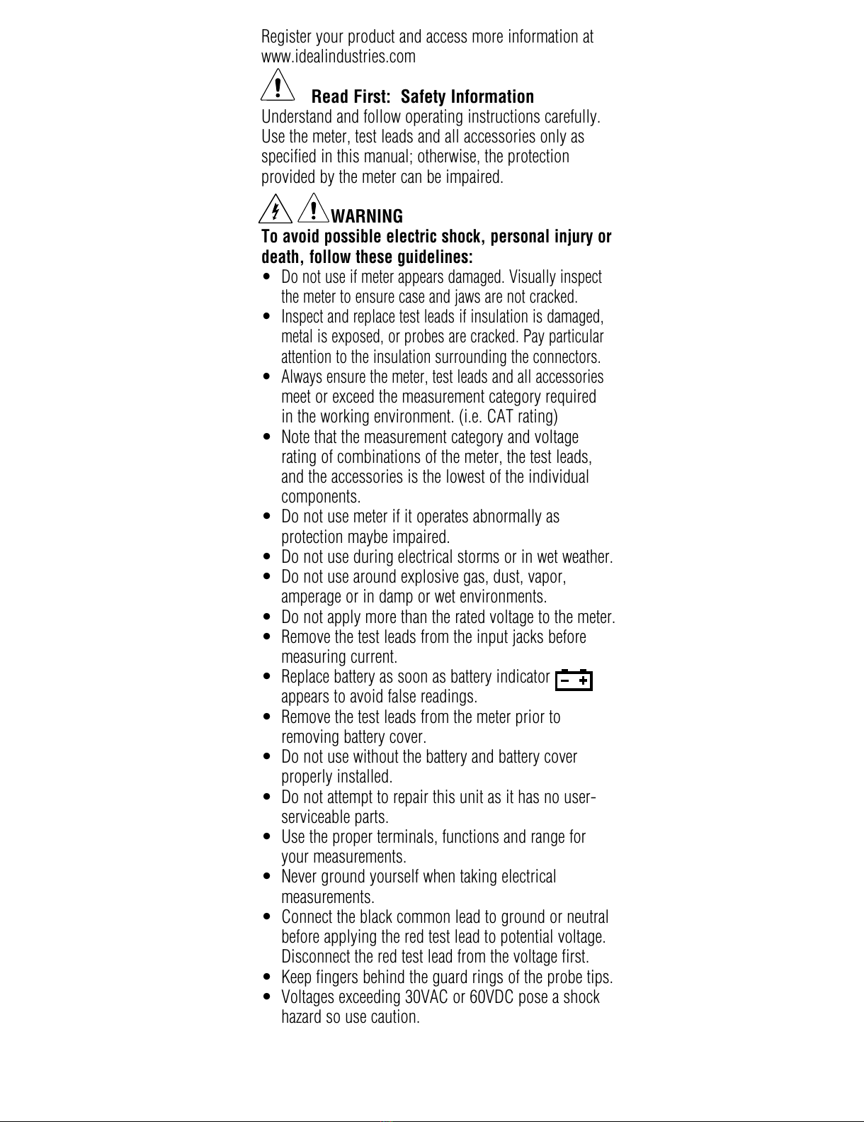
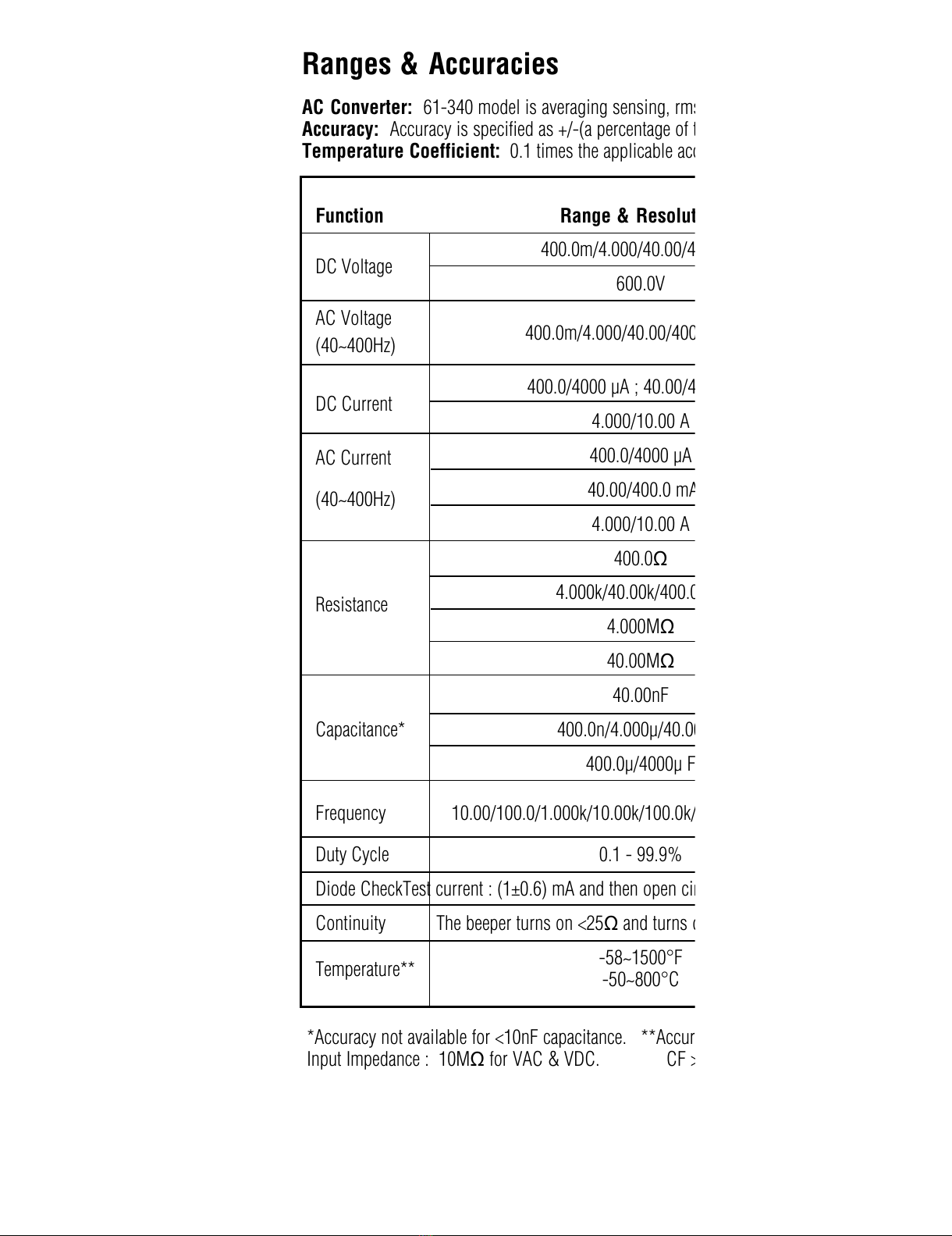
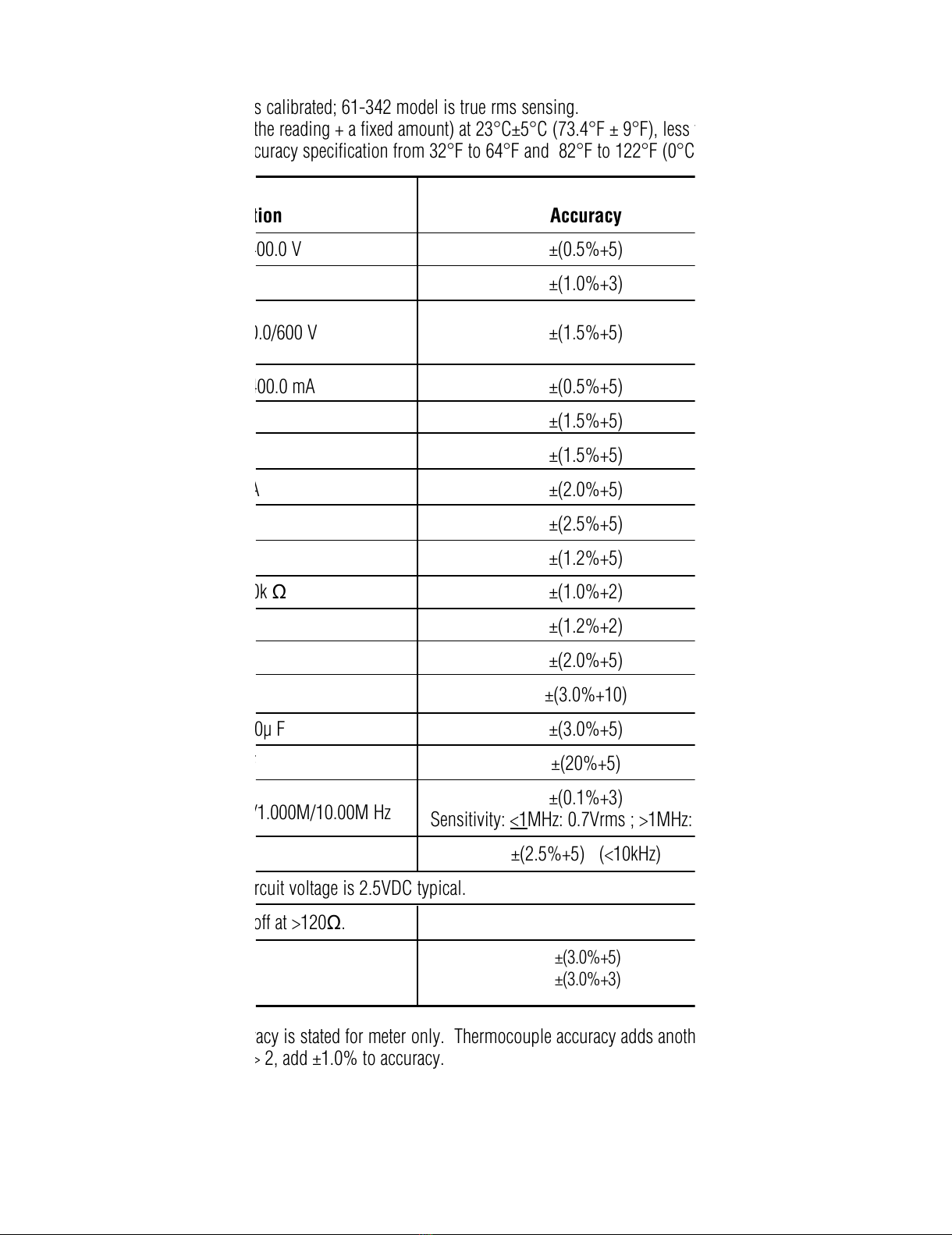
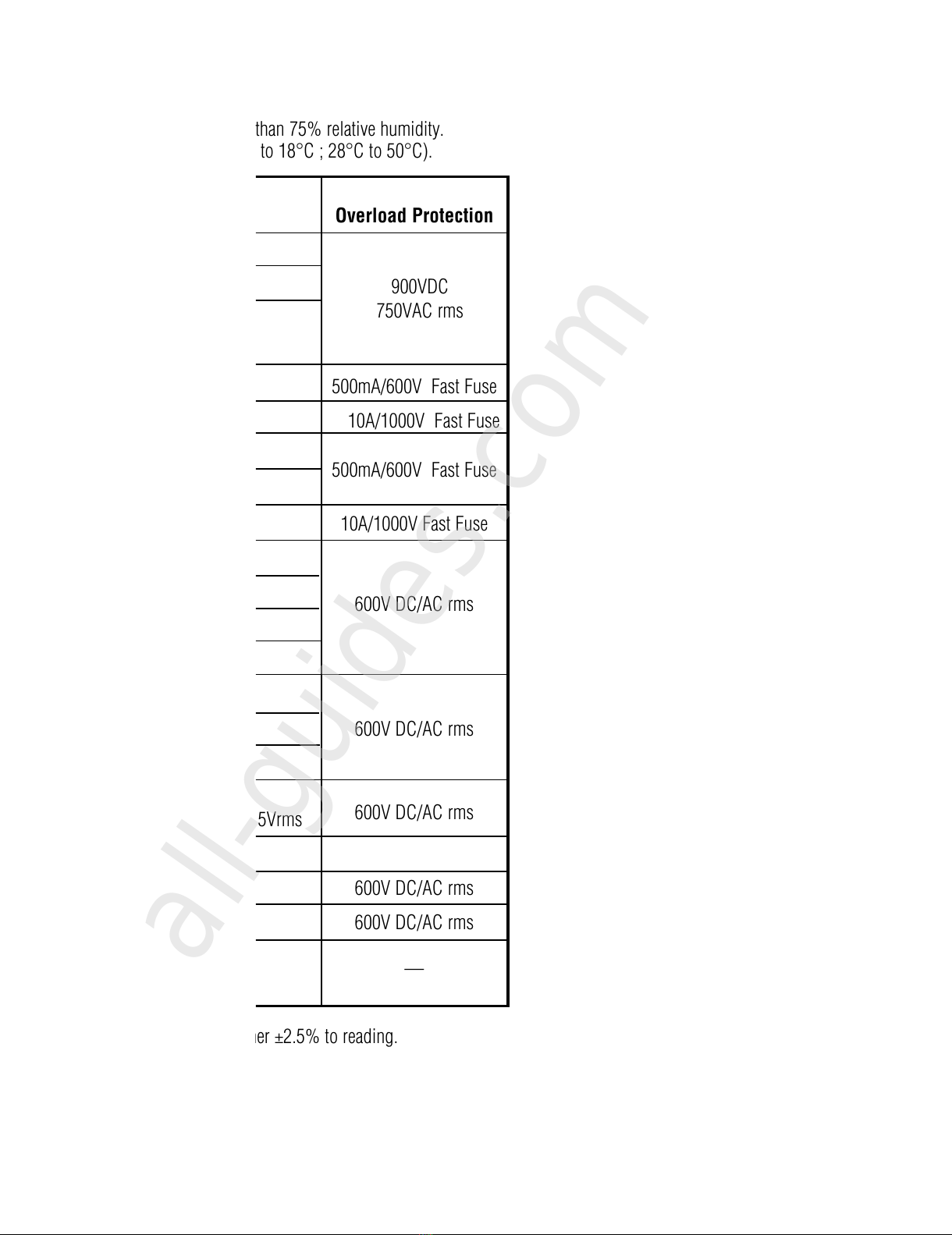
IDEAL 61-340 User manual


Other manuals for 61-340
3
This manual suits for next models
1
Table of contents
Languages:
Other IDEAL Multimeter manuals

IDEAL
IDEAL ND 4950-3 User manual

IDEAL
IDEAL 61-310 User manual

IDEAL
IDEAL 61-497 User manual

IDEAL
IDEAL 61-340 User manual

IDEAL
IDEAL ND 2385-1 User manual

IDEAL
IDEAL ND 2350-1 User manual

IDEAL
IDEAL 61-704 User manual

IDEAL
IDEAL 61-497 User manual

IDEAL
IDEAL 61-327 Use and care manual

IDEAL
IDEAL Resi-Pro 310 Series User manual

IDEAL
IDEAL ND 2351-1 User manual

IDEAL
IDEAL 61-614 User manual

IDEAL
IDEAL 61-797 User manual

IDEAL
IDEAL ND 3405-1 User manual

IDEAL
IDEAL 61-603 User manual

IDEAL
IDEAL ND-5499 User manual

IDEAL
IDEAL 61-494 User manual

IDEAL
IDEAL 602 User manual

IDEAL
IDEAL ND 2365-1 User manual

IDEAL
IDEAL ND 3511-1 User manual


Popular Multimeter manuals by other brands


Gossen MetraWatt
Gossen MetraWatt METRAmax 6 operating instructions

PeakTech
PeakTech 4000 Procedure of calibration

YOKOGAWA
YOKOGAWA 90050B user manual

Gossen MetraWatt
Gossen MetraWatt METRALINE DMM16 operating instructions

Fluke
Fluke 8846A Programmer's manual

Tempo Communications
Tempo Communications MM200 instruction manual


