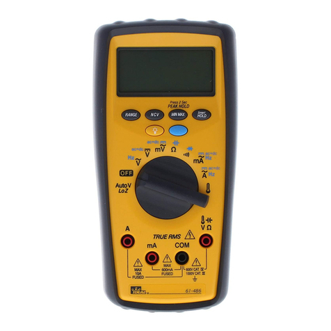
IDEAL 480 Series User manual

2
#61-484
#61-486
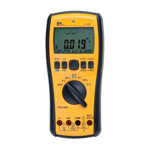
480 Series Digital Multimeter
Instruction Manual
Register your product and access more information at
www.idealindustries.com
Read First: Safety Information
Understand and follow operating instructions carefully. Use the
meter, test leads and all accessories only as specified in this manual;
otherwise, the protection provided by the meter can be impaired.
WARNING
To avoid possible electric shock, personal injury or death,
follow these guidelines:
• Donotuseifmeterappearsdamaged.Visuallyinspectthemeter
to ensure case and jaws are not cracked.
• Inspectandreplacetestleadsifinsulationisdamaged,metalis
exposed, or probes are cracked. Pay particular attention to the
insulation surrounding the connectors.
• Alwaysensurethemeter,testleadsandallaccessoriesmeet
or exceed the measurement category required in the working
environment.(i.e.CATrating)
• Notethatthemeasurementcategoryandvoltageratingof
combinations of the meter, the test leads, and the accessories is
the lowest of the individual components.
• Donotusemeterifitoperatesabnormallyasprotectionmaybe
impaired.
• Donotuseduringelectricalstormsorinwetweather.
• Donotusearoundexplosivegas,dust,vapor,amperageorin
damp or wet environments.
• Donotapplymorethantheratedvoltagetothemeter.
• Removethetestleadsfromtheinputjacksbeforemeasuring
current.
• Replacebatteryassoonasbatteryindicatorappearstoavoid
false readings.
•
Remove the test leads from the meter prior to removing battery cover
.
• Donotusewithoutthebatteryandbatterycoverproperlyinstalled.
•
Donotattempttorepairthisunitasithasnouser-serviceableparts
.
•
Use the proper terminals, functions and range for your measurements
.
• Nevergroundyourselfwhentakingelectricalmeasurements.
• Connecttheblackcommonleadtogroundorneutralbefore
applyingtheredtestleadtopotentialvoltage.Disconnectthered
test lead from the voltage first.
• Keepfingersbehindtheguardringsoftheprobetips.
• Voltagesexceeding30VACor60VDCposeashockhazardsouse
caution.
CAUTION
Toprotectyourself,think“SafetyFirst”:
• Complywithlocalandnationalsafetycodes.
61-486
Volt SenseRange Min Max
Press 2 Sec
PEAK HOLD
Smart
HOLD
A
Auto
V
LoZ
OFF
MAX
10A
FUSED
MAX
600mA
FUSED
600V CAT IV
1000V CAT III
mA COM
V Ω
TRUE RMS
Hz
Hz
V
ac+dc ac+dc
ac+dc
ac+dc
VmV
mA
A
Ω

3 4
61-486
Volt SenseRange Min Max
Press 2 Sec
PEAK HOLD
Smart
HOLD
A
Auto
V
LoZ
OFF
MAX
10A
FUSED
MAX
600mA
FUSED
600V CAT IV
1000V CAT III
mA COM
V Ω
TRUE RMS
Hz
Hz
V
ac+dc ac+dc
ac+dc
ac+dc
VmV
mA
A
Ω
3
•
Use appropriate personal protective equipment such as face
shields, insulating gloves, insulating boots, and/or insulating mats.
• Beforeeachuse:
- Performacontinuitytestbytouchingthetestleadstogetherto
verify the functionality of the battery and test leads.
- Usethe3PointSafetyMethod.(1)Verifymeteroperationby
measuringaknownvoltage.(2)Applymetertocircuitunder
test.(3)Returntotheknownlivevoltageagaintoensure
proper operation.
• Alwaysworkwithapartner.
Symbolsasmarkedonthemeterandinstructionmanual
Unsafe Voltage
Toalertyoutothepresenceofapotentiallyhazardous
voltage,whentheTesterdetectsavoltage≥30Vora
voltageoverload(OL)inV,mV.The““symbolis
displayed and High voltage indicator is activated.
Meter Description
FrontPanelIllustration
1. LCDdisplay:6000counts
2. Push-buttons.
3. RotaryswitchtoturnthePowerOn/Offandselectthe
function.
4. InputTerminalforA.
5. InputTerminalforV,Ω,,Hz,°C/F°functions.
6. Common(Groundreference)InputTerminal.
7. InputTerminalformA.
1 Display
2 Buttons
3 Rotary
Switch
5 V, Ω,
,
C°/F°
Input
6 Common
Input
7 mA Input
4 A Input
RiskofDanger.ImportantInformation.SeeManual.
Hazardousvoltage.Riskofelectricalshock.
ApplicationaroundandremovalfromHazardousLive
conductors is permitted.
AC(AlternatingCurrent)
DC(DirectCurrent)
EarthGround
CAT II MeasurementCategoryIIappliestotestandmeasuringcir-
cuitsconnecteddirectlytoutilizationpoints(socketoutlets
andsimilarpoints)ofthelow-voltageMAINSinstallation
CAT III MeasurementCategoryIIIappliestomeasuringcircuits
connectedtothedistributionpartofthebuilding’slow-
voltageMAINSinstallation
CAT IV MeasurementCategoryIVappliestotestandmeasuring
circuitsconnectedatthesourceofthebuilding’slow-
voltageMAINSinstallation
~
...

5 6
Features
•6000countdigitaldisplay
•62segmentbargraph
•Extralargescaledisplaywithwhitebacklight
•TrueRMS
•0.08%basicDCVaccuracy
•AutomaticAC/DCvoltagedetectwithlowimpedance
(Auto-VLoZ)
•VoltSense(Non-ContactVoltagedetect)
•SmartDatahold
•PeakHold(1ms)(61-486only)
•Min/Maxfunction
•AC+DCfunction
•FrequencycounteronACmode
•Capacitancemeasurement
•Temperature(61-486only)
•Lowbatteryindicatorwithsegments
•AutoPoweroff(20minutes)
•Shockprooffrom4feeddrops
•CATIV600V/CATIII1000VSafetystandard
Unpacking & Inspection
UponremovingyournewDigitalMultimeterfromits
packaging,youshouldhavethefollowingitems:
1.IDEAL61-484/61-486DigitalMultimeter
2.Testleads,set(oneblack,onered)
3.TemperatureProbe(61-486only)
4.UserManual
5. Carrying Case
6.One9VBattery(installed)
Making Basic Measurements
PreparationandCautionBeforeMeasurement
:ObservetherulesofWarningsandCautions
CAUTION
When connecting the test leads to the DUT (Device
Under Test) connect the common test leads before
connecting the live test leads. When removing
the test leads, remove the live test leads before
removing the common test leads.
Measuring AC / DC Voltage
TurntherotaryswitchandpresstheFunctionbuttontoselect
the measuring function.
Test Leads
Guard ring

7 8
Measuring AC/DC Current
TurntherotaryswitchandpresstheFunctionbuttontoselect
the measuring function.
Measuring Frequency
TurntherotaryswitchandpresstheFunctionbuttontoselect
the measuring function.
Disconnect
Press the function
button to select the
measuring function.
Measuring Resistance/Capacitance
TurntherotaryswitchandpresstheFunctionbuttontoselect
the measuring function.
Measuring Continuity/Diode
TurntherotaryswitchandpresstheFunctionbuttontoselect
the measuring function.
Capacitance
Capacitance
Resistance
Resistance

9 10
Measuring Temperature °F / °C (61-486 only)
TurntherotaryswitchandpresstheFunctionbuttontoselect
themeasuringfunction.(°C/°F)
Press button > 1sec to Auto Range Mode.
AC
Switch
Position
Hz
ac+dc
ac+dc
ac+dc
ac+dc
ac+dc
Function
Press
FC
Using the Function
FunctionButton
PresstheFunctionbuttontochangethefunctiononthesame
switch position.
RANGE Button

11 12
MIN/MAX
TheMAX/MINmoderecordsthemin.andmax.inputvalues.
Whentheinputgoesbelowtherecordedmin.valueorabove
the recorded max. value, the meter records the new value.
Press Hold button to pause the recording.
Peak HOLD (61-486 only)
InthePeakHoldfunction,themeterrecordsthepeakmin.
value and the peak max. value when the inputs goes below
the recorded peak min. value or above the recorded peak
max. value ,the meter records the new value . Press Hold
button to pause the recording.
Press
button over 1 sec.
to exit this function
Min. Reading
Max. Reading
Present Reading
Press
button over 1 sec.
then exit this function
Min. Reading
Max. Reading
Press
2 sec.
Present Reading
Smart HOLD
Themeterwillbeepcontinuouslyandthedisplaywillflash
if the measured signal is larger than the display reading by
50counts.(However,itcannotdetectacrosstheACandDC
Voltage/Current).
VoltSense
KeeptheVoltSensebuttondowntoactivatetheVoltSense
function.
Caution
Thenumberofdashesdisplayingonthedisplayindicatesthe
electricfieldintensity.Ifnoindication,voltagecouldstillbe
present.Alwaysverifywithleads.

13 14
Backlight
PresstheBacklightbuttontoturnthebacklighton/off.
Disable Auto Power Off
Wake-upthemeterbydialingtheswitchorpressingany
button.
Auto Power Off Disable
Turntherotaryswitchtotheoffposition,thenpressthe
Functionbuttondownwhileturningonthemeter.
After idle 20 min.
2
1
Testing LCD Monitor
Turntherotaryswitchtotheoffposition,thenpressthe
Smart-HOLDbuttondownwhileturningonthemeter.
Fuse Replacement
2
1
Fuse 440mA (1000V)
Battery Cover
Fuse 11A (1000V)
Rear Case

15 16
Low Battery and Battery Replacement
Replace the battery as soon as the low battery indicator
appears to avoid false readings. Refer to the following figure
to replace the battery.
Caution
RemovetestleadsfromtheMeterbeforeopeningthebattery
cover or meter case.
9V Battery
Battery Cover
Screw
Specifications
General Specifications
Maximum voltage applied to any terminal:
1000Vacrmsor1000Vdc.rms
Display:6000counts.
Polarity Indication:
Automatic,positiveimplied,negativeindicated.
Overrange Indication: OL
Battery Life: 150hoursALKALINEBattery(NoBacklight)
Low Battery Indication:
Voltagedropsbelowoperatingvoltage,willflash.
Power Requirement: 9Vbattery
Auto Power Off: 20minutes.
Operating Temperature: -10~10°C
10°C~30°C(<80%RH),
30°C~40°C(<75%RH),
40°C~50°C(<45%RH)
CAT Application to Field
IThecircuitsnotconnectedtomains.
II ThecircuitsdirectlyconnectedtoLow-voltageinstallation.
III Thebuildinginstallation.
IV ThesourceoftheLow-voltageinstallation.
N12966
Storage Temperature:
-20°Cto60°C,0to80%R.H.(batteriesnotfitted)
Temperature Coefficient:
0.15x(Spec.Accy)/°C,<18°Cor>28°C.
Measure: Samples3timespersecond.
Altitude: 6561.7ft(2000m)
Safety Certification: ComplieswithEN61010-1,
UL61010-1,IEC61010-1,CATIV600V,CATIII1000V
Double Insulation
Instrumenthasbeenevaluatedandcomplieswithinsulation
categoryIV(overvoltagecategoryIV).Pollutiondegree2in
accordancewithIEC-644.Indooruse.
Compliance to EN 61557: IEC61557-1,IEC61557-2,
IEC61557-4,IEC61557-10
Weight:460g(includingbattery)
Dimensions (W x H x D):
94mmx190mmx48mmwithholster.
Accessories Included:9VBattery(installed),Testleads
(TL-484)andusermanual.
EMC: EN61326-1
Shock vibration: Sinusoidalvibrationper
MIL-PRF-28800F(5~55Hz,3gmax.)
Drop Protection: 4 ft. drop onto hardwood over concrete
floor.

17 18
Electrical Specifications
Accuracyis±(%reading+numberofdigits)at23°C±5°C
<80%RH.
(1) Voltage
Range Resolution For 61-484
Accuracy
For 61-486
Accuracy
60.00mVDC 0.01mV ±(0.08%+10d)
600.0mVDC 0.1mV ±(0.1%+2d) ±(0.08%+2d)
6.000VDC 0.001V ±(0.09%+2d) ±(0.08%+2d)
60.00VDC 0.01V ±(0.09%+2d) ±(0.08%+2d)
600.0VDC 0.1V ±(0.09%+2d) ±(0.08%+2d)
1000VDC 1V ±(0.09%+2d) ±(0.08%+2d)
60.0mVAC 0.01mV ±(1.20%+5d)
600.0mVAC 0.1mV ±(1.5%+5d) ±(1.20%+5d)
6.000VAC 0.001V ±(1.0%+3d) ±(0.80%+5d)
60.00VAC 0.01V ±(1.0%+3d) ±(0.80%+5d)
600.0VAC 0.1V ±(1.0%+3d) ±(0.80%+5d)
1000VAC 1V ±(1.0%+3d) ±(0.80%+5d)
Input Protection : 1000VDCor1000VAC rms
AC Frequency Response : 50Hz~1KHz
Input Impedance : 10MΩ,<100pF
AC Conversion Type :
ACconversionsareac-coupled,truermsresponding,
calibrated to the sine wave input.
Fornon-sinewaveaddthefollowingCrestFactorcorrections:
ForCrestFactorof1.4to2.0,add1.0%toaccuracy.
ForCrestFactorof2.0to2.5,add2.5%toaccuracy.
ForCrestFactorof2.5to3.0,add4.0%toaccuracy.
(2) Auto-V
Range Resolution For 61-484
Accuracy
For 61-486
Accuracy
600.0VAC 0.1V
±(1.0%+3d) ±(0.80%+3d)
1000VAC 1V
600.0VAC 0.1V
1000VAC 1V
Input Protection : 1000VDCor1000VACrms
AC Frequency Response : 50Hz~1KHz
Input Impedance :Approx.3kΩ.
AC Conversion Type :
Conversion type and additional specification are same as
voltage function.
(3) Current
Range Resolution For 61-484
Accuracy
For 61-486
Accuracy
60.00mADC 0.01mA ±(1.0%+3d) ±(0.08%+3d)
600.0mADC 0.1mA ±(1.0%+3d) ±(0.08%+3d)
6.000aDC 0.001A ±(1.0%+3d) ±(0.08%+3d)
10.00ADC 0.01A ±(1.0%+3d) ±(0.08%+3d)
60.0mAAC 0.01mA ±(1.5%+3d) ±(1.2%+3d)
600.0mAAC 0.1mA ±(1.5%+3d) ±(1.2%+3d)
6.000AAC 0.001A ±(1.5%+3d) ±(1.2%+3d)
10.00AAC 0.01A ±(1.5%+3d) ±(1.2%+3d)
Input Protection :
EquippedwithHighEnergyFuse.
440mA,1000VAC/DC10KAFuseformAinput.
11A,1000VAC/DC20KAFuseforAinput.
Max. Measuring Time :3minutesforAinput,10minutes
formAinput.
Resttime20minutesmin.
AC Conversion Type :
Conversion type and additional specification are same as
volt-agefunction.
AC Frequency Response : 50Hz~1KHz
19 20
(4) Peak Hold (for 61-486 only) : Specifiedaccuracy
±150d.
(5) Resistance
Range Resolution Accuracy
600.0Ω0.1Ω±(0.08%+5d)
6.000KΩ0.001KΩ
±(0.08%+2d)
60.00KΩ0.01KΩ
600.0KΩ0.1KΩ
6.000MΩ0.001mΩ
40.00MΩ*0.01MΩ±(1.0%+5d)
Input Protection : 1000VDCor1000VACrms
Max. Open Circuit Voltage :
Approx.2.5Vfor600Ω&6kΩRange.
Approx.0.6Vforothers.
Max. Test Current : Approx.0.1mA.
(6) Continuity Check
Range Resolution Accuracy
600.0Ω0.1Ω±(0.8%+5d)
Input Protection : 1000VDCor1000VACrms
Max. Open Circuit Voltage : Approx.2.5V
Max. Test Current : Approx.0.1mA
Continuity Threshold : <30ΩBeepOn.
>100ΩBeepOFF.
Continuity Indicator : 2.7KHzToneBuzzer
(7) Diode Test
Range Resolution Accuracy
2.000V 1mV ±(1.5%+2d)
Input Protection : 1000VDCor1000VACrms
Max. Open Circuit Voltage : Approx.2.5V
Max.Test Current : Approx.0.4mA
(8) Capacitance
Range Resolution Accuracy
1.000μF 0.001μF
±(1.2%+2d)
10.00μF 0.01μF
100.0μF 0.1μF
1.000mF 0.001mF
10.00mF 0.01mF
Input Protection : 1000VDCor1000VACrms
Max. Measuring Time : 0.7secfor1nF~1mF
3secfor1mF~10mF
(9) Frequency Counter
Range Resolution Accuracy
100.00Hz 0.1Hz
±(0.1%+2d)
1000.0Hz 0.1Hz
10.000KHz 0.001KHz
100.00KHz 0.01KHz
Input Protection : 1000VDCor1000VACrms
Min. Frequency : 1Hz
Sensitivity : >5.0Vp-p(forACV1HZ~10kHz).
>10Vp-p(forACV10kHZ~100kHz)
>2mAp-p(forACmA)
>0.2Ap-p(forACA)
(10) Temperature (For 61-486 only)
Range Resolution Accuracy*
-40.0°C~400°C 0.1°C ±(1.0%+10d)
-40.0°F~752°F 0.1°F ±(1.0%+18d)
Input Protection :1000VDCor1000VACrms
* Doesnotincludeaccuracyofthethermocoupleprobe.
* Accuracyspecificationassumessurroundingtemperature
stableto±1°C.Forsurroundingtemperaturechangesof
±5°C,ratedaccuracyappliesafter2hours.
Note : TheAC+DCTrueRMSvaluemightbeoverthe
selectedrangesincetheACsignalmayaddontheDClevel.

21 22
Maintenance
Donotattempttorepairthismeter.Itcontainsnouser
serviceable parts. Repair or servicing should only be
performed by qualified personnel.
Cleaning
Periodically,wipethecasewithadryclothanddetergent.Do
not use abrasives or solvents.
(11) AC+DC Voltage
Range Resolution For 61-484
Accuracy For 61-486
Accuracy
6.000V 0.001V
±(2.5%+5d) ±(2%+5d)
60.00V 0.01V
600.0V 0.1V
1000V 1V
Additionalspecificationsarethesameasvoltagefunction.
(12) AC+DC mV
Range Resolution For 61-484
Accuracy For 61-486
Accuracy
60.00mV 0.1mV ±(2%+10d)
600.0mV .1mV ±(2.5%+5d)
Additionalspecificationsarethesameasvoltagefunction.
(13) AC+DC mA
Range Resolution For 61-484
Accuracy For 61-486
Accuracy
60.00mA 0.1mA ±(2.5%+5d) ±(2%+5d)
600.0mA .1mA
Additionalspecificationsarethesameascurrentfunction.
(14) AC+DC A
Range Resolution For 61-484
Accuracy For 61-486
Accuracy
600.0A 0.001VA ±(2.5%+5d) ±(2%+5d)
10.00A 0.01A
Additionalspecificationsarethesameascurrentfunction.

2423
Dispose of waste electrical and electronic equipment
Inordertopreserve,protectandimprovethequalityof
environment,protecthumanhealthandutilizenatural
resources prudently and rationally, the user should return
unserviceable product to relevant facilities in accordance
withstatutoryregulations.Thecrossed-outwheeledbin
indicates the product needs to be disposed separately and
not as municipal waste.
Disposal of used batteries/accumulators!
Theuserislegallyobligedtoreturnusedbatteriesand
accumulators.Disposingusedbatteriesinthehousehold
wasteisprohibited!Batteries/accumulatorscontaining
hazardoussubstancesaremarkedwiththecrossed-out
wheeledbin.Thesymbolindicatesthattheproductisforbidden
tobedisposedviathedomesticrefuse.Thechemicalsymbolsfor
therespectivehazardoussubstancesareCd = Cadmium, Hg =
Mercury,Pb = Lead.
You can return used batteries/accumulators free of charge to any
collecting point of your local authority, our stores, or where bat-
teries/accumulators are sold. Consequently you comply with your
legal obligations and contribute to environmental protection.
Warranty Statement:
Thistesteriswarrantedtotheoriginalpurchaseragainstdefectsin
material and workmanship for two years from the date of purchase.
Duringthiswarrantyperiod,IDEALINDUSTRIES,INC.will,atits
option, replace or repair the defective unit, subject to verification
ofthedefectormalfunction.Thiswarrantydoesnotapplyto
defectsresultingfromabuse,neglect,accident,unauthorizedrepair,
alteration, or unreasonable use of the instrument.
AnyimpliedwarrantiesarisingoutofthesaleofanIDEALproduct,
including but not limited to implied warranties of merchantability
andfitnessforaparticularpurpose,arelimitedtotheabove.The
manufacturer shall not be liable for loss of use of the instrument or
other incidental or consequential damages, expenses, or economic
loss, or for any claim or claims for such damage, expenses or
economic loss.
Statelawsvary,sotheabovelimitationsorexclusionsmaynot
applytoyou.Thiswarrantygivesyouspecificlegalrights,andyou
may also have other rights which vary from state to state.
Warrantydoesnotcoverbatteriesortestleads.

25 2626
#61-484
#61-486
Multímetro digital serie 480
Manual de Instrucciones
61-486
Volt SenseRange Min Max
Press 2 Sec
PEAK HOLD
Smart
HOLD
A
Auto
V
LoZ
OFF
MAX
10A
FUSED
MAX
600mA
FUSED
600V CAT IV
1000V CAT III
mA COM
V Ω
TRUE RMS
Hz
Hz
V
ac+dc ac+dc
ac+dc
ac+dc
VmV
mA
A
Ω
Registre su producto y acceda a más información en www.
idealindustries.com
Lea Primero: Información de Seguridad
Entienda y siga las instrucciones de operación cuidadosamente. Use
el multímetro, las sondas y todos los accesorios únicamente como
se especifica en este manual; de lo contrario, la protección que
proporciona el multímetro puede verse perjudicada.
ADVERTENCIA
Para evitar posibles riesgos de descarga eléctrica, lesiones o la
muerte,sigaestasdirectrices:
• Nouseelmultímetrosielmismopareceestardañado.
Inspecciónelovisualmenteparaasegurarsedequelacubiertayla
pinzanoesténquebradas.
• Inspeccioneyreemplaceloscablessielaislamientoestádañado,
hay metal expuesto o las sondas están quebradas. Preste atención
especial al aislante alrededor de los conectores.
•
Siempreasegúresedequeelmultímetro,lassondasytodoslos
accesorios cumplan o excedan la categoría de medición necesaria en
elambientedetrabajo.(Porejemplo,clasificaciónCAT)
• Tomenotadequelacategoríademediciónylaclasificación
de voltaje de combinaciones del multímetro, la sondas y los
accesorios es la más baja de los componentes individuales.
• Nouseelmultímetrosifuncionaenformaanormal,porquela
protección puede estar perjudicada.
• Nouseelmultímetrodurantetormentaseléctricasoenclima
húmedo.
• Nouseelmultímetrocercadegas,polvo,vapor,amperaje
explosivo o en ambientes húmedos o mojados.
• Noapliquevoltajessuperioresalasnominalesalmultímetro.
•
Quite las sondas de los puertos de entrada antes de medir corriente.
• Reemplacelabateríatanprontoaparezcaelindicadordecargade
batería baja, para evitar las lecturas falsas.
•
Retire las sondas del multímetro antes de quitar la tapa de la batería.
• Nouseelmultímetrosinlabatería,nisinlatapadelabatería
correctamente instalada.
• Nointenterepararestaunidadyaquenotienepiezasreparablespor
el usuario.
•
Use las terminales, funciones y rangos apropiados para sus medidas.
• Noseconecteatierracuandotomemedidaseléctricas.
• Conectelasondanegracomúnatierraoaneutroantesdetocarla
sondarojaavoltajepotencial.Desconectelasondarojadelvoltaje
primero.
• Mantengalosdedosdetrásdelosanillosprotectoresenlaspuntas
de las sondas.

27 28
61-486
Volt SenseRange Min Max
Press 2 Sec
PEAK HOLD
Smart
HOLD
A
Auto
V
LoZ
OFF
MAX
10A
FUSED
MAX
600mA
FUSED
600V CAT IV
1000V CAT III
mA COM
V Ω
TRUE RMS
Hz
Hz
V
ac+dc ac+dc
ac+dc
ac+dc
VmV
mA
A
Ω
27
Voltaje Peligroso
Para advertirle de la presencia de voltaje potencialmente
peligroso,cuandoelinstrumentodetectaunvoltaje=30Vo
unasobrecargadevoltaje(OL)enV,mV.Elsímbolo“”
sedespliegayelindicadordeAltoVoltajeseactiva.
Descripción del Medidor
IlustracióndelPanelFrontal
1. PantallaLCD:resoluciónde6000
2. BotonesparaPresionar
3. InterruptorgiratorioparaEncender/Apagaryseleccionar
la función.
4. TerminaldeEntradaparaA.
5. TerminaldeEntradaparalasfuncionesV,Ω,insert
symbol,Hz,°C/°F.
6. TerminaldeEntradaComún(Referenciadetierra).
7. TerminaldeEntradaparamA.
1 Pantalla
2 Botones
3 Interruptor
giratorio
5 Entrada
V, Ω, ,
Hz, °C
6 Entrada
Común
7 Entrada mA
4 Entrada A
•Losvoltajessuperioresa30VCAo60VCDrepresentanun
riesgo de descarga eléctrica, así que tenga precaución.
PRECAUCIÓN
Paraprotegerse,piense“¡Laseguridadprimero!”:
• Cumplaconlosrequisitosdeseguridadlocalesynacionales.
• Useequiposdeprotecciónpersonalapropiados,talescomo,
caretas,guantesaislantes,calzadoy/oalfombrasaislantes.
•Antesdecadauso:
- Realiceunapruebadecontinuidadponiendoencontacto
las sondas para verificar el funcionamiento de la batería y
de las sondas.
- UseelMétododeSeguridadde3Puntos.(1)Verifiqueel
funcionamiento del multímetro midiendo un voltaje
conocido.(2)Apliqueelmultímetroalcircuitoenprueba.
(3)Vuelvaalvoltajeconectadoconocidoparaasegurarel
funcionamiento correcto.
•Siempretrabajeconuncompañero.
Símbolos de la unidad
Riesgo.InformaciónImportante.VeaelManual.
Voltajepeligroso.Peligrodechoqueeléctrico.
Sepermitelaaplicaciónyelretirodealrededoryde
ConductoresEnergizados.
CA(CorrienteAlterna)
CD(CorrienteDirecta)
Tierra
CAT II
CategoríadeMediciónIIaplicaalapruebaymediciónde
circuitosdirectamenteconectadosapuntosdeutilización
(tomacorrientesypuntossimilares)delainstalacióndela
red eléctrica de bajo voltaje
CAT III CategoríadeMediciónIIIaplicaalamedicióndecircuitos
conectados a la parte de distribución de la instalación de
la red eléctrica de bajo voltaje del edificio
CAT IV CategoríadeMediciónIVaplicaalapruebaymediciónde
circuitos conectados a la fuente de la instalación de la red
eléctrica de bajo voltaje del edificio
~
...

29 30
Caractéristiques
•Pantalladigitalderesoluciónde6000
•Gráficadebarrade62segmentos
•Pantallaextragrandeconluzdefondoblanca
•RMSverdadero
•PrecisióndeVCDbásicade0.08%
•DetecciónautomáticadevoltajeCA/CDconbaja
impedancia(Auto-VLoZ)
•VoltSense(Deteccióndevoltajesincontacto)
•RetencióndeDatosInteligente
•RetencióndePico(1ms)(únicamente61-486)
•FunciónMin/Max
•FunciónCA+CD
•ContadordefrecuenciaenelmodoCA
•Medicióndecapacitancia
•Temperatura(únicamente61-486)
•Indicadordebateríabajaconsegmentos
•Apagadoautomático(20minutos)
•Apruebadegolpesencaídasde4pies
•EstándardeseguridadCATIV600V/CATIII1000V
Desembalaje e Inspección
AlsacarsunuevoMultímetroDigitaldesuembalaje,usted
debetenerlossiguientesartículos:
1.MultímetroDigitalIDEAL61-484/61-486
2.Unjuegodecablesdeprueba(unonegro,unorojo)
3.SondadeTemperatura(únicamente61-486)
4.ManualdeUsuario
5. Estuche
6.1bateríade9V(instalada)
Realizar Medidas Básicas
PreparaciónyCautelaAntesdelaMedición:Observelas
reglasdeAvisosyCautela
ADVERTENCIA
Cuando conecte los cables de prueba al DBP
(Dispositivo Bajo Prueba) conecte el cable de
prueba común antes de conectar el cable de prueba
vivo. Al quitar los cables de prueba, quite el cable
de prueba vivo antes de quitar el cable de prueba
común.
Medición de Voltaje CA/CD
GireelinterruptorgiratorioypresioneelbotóndeFunción
para seleccionar la función de medición.
Sondas
Anillo Protector

31 32
Medición de Voltaje CA/CD
GireelinterruptorgiratorioypresioneelbotóndeFunción
para seleccionar la función de medición.
Medición de Frecuencia
GireelinterruptorgiratorioypresioneelbotóndeFunción
para seleccionar la función de medición.
Desconectar
Presione el botón
de Función para s
eleccionar la función
de medición.
Medición de la Resistencia/Capacitancia
GireelinterruptorgiratorioypresioneelbotóndeFunción
para seleccionar la función de medición.
Medición de Continuidad/Diodo
GireelinterruptorgiratorioypresioneelbotóndeFunción
para seleccionar la función de medición.
Capacitance
Capacitance
Resistance
Resistance

33 34
Medición de la Temperatura °F / °C (únicamente
61-486)
GireelinterruptorgiratorioypresioneelbotóndeFunción
paraseleccionarlafuncióndemedición.(°C/°F)
Press button > 1sec to Auto Range Mode.
AC
Switch
Position
Hz
ac+dc
ac+dc
ac+dc
ac+dc
ac+dc
Function
Press
FC
Uso de la Función
BotóndelaFunción
PresioneelbotóndeFunciónparacambiarlafunciónenla
misma posición del interruptor.
Botón de RANGO (RANGE)

35 36
MIN/MAX
ElmodoMIN/MAXgrabalosvaloresdeentradamin.ymáx.
Cuando la entrada cae por debajo del valor min. grabado o
sube por encima del valor máx. grabado, el medidor graba el
nuevovalor.PresioneelbotónHold(Detener)parapausarla
grabación.
RENTENCIÓN de Pico (únicamente 61-486)
EnlaFuncióndeRetencióndePico,elmedidorgrabael
valor de pico min. y el valor de pico máx. cuando la entrada
cae por debajo del pico min. grabado o sube por encima del
valor máx. grabado, el medidor graba el nuevo valor.
Press
button over 1 sec.
to exit this function
Min. Reading
Max. Reading
Present Reading
Press
button over 1 sec.
then exit this function
Min. Reading
Max. Reading
Press
2 sec.
Present Reading
RETENCIÓN inteligente
El medidor pitará continuamente y la pantalla destellará si
laseñalqueseestámidiendoesmayoralalecturadela
pantallaporunaresoluciónde50.(Sinembargo,nopuede
detectaratravésdelVoltaje/CorrienteCAylaCD).
VoltSense
MantengaelbotóndeVoltSenseparaactivarlafunciónde
VoltSense.
Advertencia
El número de guiones que se muestran en la pantalla indican
laintensidaddelcampoeléctrico.Sinohayindicación,aún
debedehabervoltaje.Siempreverifiqueconloscablesde
prueba.

37 38
Luz de Fondo
PresioneelbotóndeLuzdeFondoparaencender/apagarla
luzdefondo.
Deshabilitar el Apagado Automático
Activeelmedidorgirandoelinterruptoropresionando
cualquier botón.
Deshabilitar el Apagado Automático
Gireelinterruptorgiratorioalaposicióndeapagado,luego
presioneelbotóndeFunciónmientrasenciendeelmedidor.
After idle 20 min.
2
1
Prueba de la Pantalla LCD
Gireelinterruptorgiratorioalaposicióndeapagado,luego
presioneelbotonSmart-Holdmientrasenciendeelmedidor.
Reemplazo del Fusible
2
1
Fuse 440mA (1000V)
Battery Cover
Fuse 11A (1000V)
Rear Case
Después de
estar sin utilizar
20 min.
Fusible de 440
mA (1000 V) Fusible de 11 A
(1000 V)
Cubierta de la
batería
Carcasa Trasera

39 40
Batería Baja y el Reemplazo de la Batería
Reemplacelabateríatanprontoaparezcaelindicadorde
batería baja para evitar lecturas falsas. Haga referencia a la
siguientefiguraparareemplazarlabatería.
Advertencia
Quite los cables de prueba antes de abrir la cubierta de la
batería o carcasa del medidor.
9V Battery
Battery Cover
Screw
Especificaciones
Características Generales
Voltaje máximo aplicado a cualquier terminal:
1000VCArmso1000VDCrms
Pantalla:resoluciónde6000
Indicadores de Polaridad:
Automático,positivoimplicado,negativoindicado.
Indicador de Fuera de Rango: OL
Duración de la Batería:150horasBateríaALCALINA(sin
luzdefondo)
Indicador de Batería Baja:
El voltaje baja por debajo del voltaje de operación,
parpadeará.
Requisitos de Potencia: Bateríade9V
Apagado Automático:20minutos.
Temperatura de Funcionamiento: t-10~10°C
10°C~30°C(<80%HR),
30°C~40°C(<75%HR),
40°C~50°C(<45%HR)
CAT Aplicación al Campo
IEl circuito no está conectado a la red eléctrica.
II El circuito está conectado directamente a una instalación de
Bajo-voltaje.
III Instalacióndeledicio.
IV LafuentedelainstalacióndeBajo-voltaje.
N12966
Temperatura de Almacenamiento:
-20°Ca60°C,0a80%H.R.(sinbateríasinstaladas)
Coeficiente de Temperatura:
0.15x(Prec.Espec.)/°C,<18°Có>28°C.
Medición: Toma3muestrasporsegundo.
Altitud: 6561.7pies(2000m)
Certificación de Seguridad: CumpleconEN61010-1,
UL61010-1,IEC61010-1,CATIV600V,CATIII1000V
Aislamiento Doble
El instrumento ha sido evaluado y cumple con la categoría
IVdeaislamiento(categoríaIVdesobrevoltaje).Grado2de
contaminacióndeacuerdoconIEC-644.Usoeninteriores.
Cumple con EN 61557: IEC61557-1,IEC61557-2,
IEC61557-4,IEC61557-10
Peso:460g(conlabateríaincluida)
Dimensiones (A x A x P):
94mmx190mmx48mmconestuche.
Accesorios incluidos: Bateríade9V(instalada),Cables
deprueba(TL-484)ymanualdeusuario.
EMC: EN61326-1
Vibración de impacto: VibraciónsinusoidalsegúnMIL-
PRF-28800F(5~55Hz,3gmáximo).
Protección contra caídas: Caída de 4 pies a madera
sobre piso de concreto.
Cubierta de la
Batería
Batería de 9V
Tornillo
This manual suits for next models
2
Table of contents
Languages:
Other IDEAL Multimeter manuals

IDEAL
IDEAL 61-614 User manual

IDEAL
IDEAL 61-605 User manual

IDEAL
IDEAL 61-603 User manual

IDEAL
IDEAL 61-354 (TRMS) User manual

IDEAL
IDEAL 61-340 User manual

IDEAL
IDEAL 61-310 User manual

IDEAL
IDEAL ND 2351-1 User manual

IDEAL
IDEAL 61-797 User manual

IDEAL
IDEAL ND 3405-1 User manual

IDEAL
IDEAL 61-340 User manual

IDEAL
IDEAL 61-357 Use and care manual

IDEAL
IDEAL 61-340 User manual

IDEAL
IDEAL ND 2366-1 User manual

IDEAL
IDEAL 61-681 User manual

IDEAL
IDEAL 61-704 User manual

IDEAL
IDEAL 61-337 Use and care manual

IDEAL
IDEAL ND 2365-1 User manual

IDEAL
IDEAL Resi-Pro 310 Series User manual

IDEAL
IDEAL ND 2352-1 User manual

IDEAL
IDEAL 61-327 Use and care manual