IHP PCBE-325 User manual

KIT CONTENTS
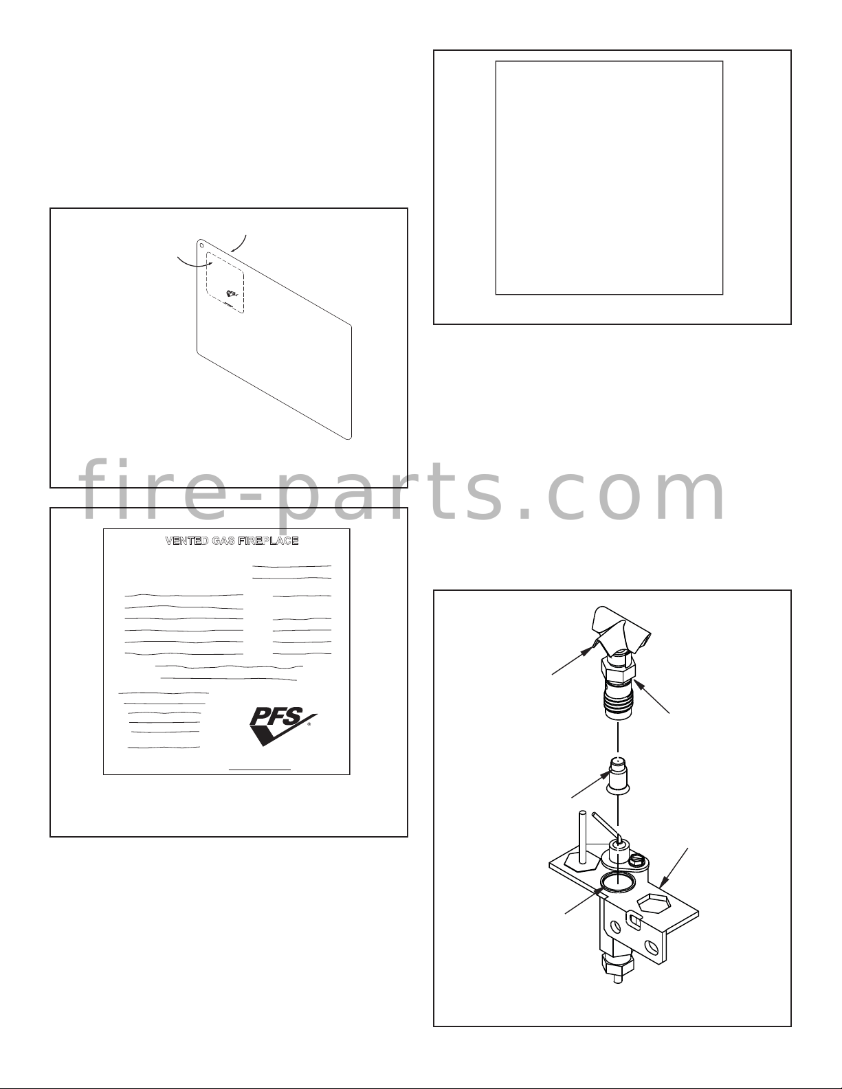
1 ea. Pilot Orifice LP (#14)
1 ea. Main Burner Orifice (#54)
1 ea. Air-Mixer Brass LP
1 ea. Gas Valve Regulator LP
1 ea. Conversion Label, English
1 ea. Conversion Label, French
1 ea. Conversion Information Label
1 ea. Instruction Sheet
REQUIRED TOOLS AND SUPPLIES
7/8” Open End Wrench or Adjustable Wrench
3/4” Open End Wrench or Adjustable Wrench
3/8” Deep Socket Drive
Torx T20 or Slotted Screwdriver
5/32” Allen Wrench
#2 Short Phillips Screwdriver
Thread Sealant (Resistant to Propane/LP)
TURN OFF THE GAS SUPPLY TO THE APPLIANCE. DISCONNECT
ELECTRICAL POWER SUPPLY.
READ ALL THE STEPS BEFORE STARTING THE CONVERSION. IN-
STALLER NOTICE: THESE INSTRUCTIONS MUST BE LEFT WITH THE
APPLIANCE.
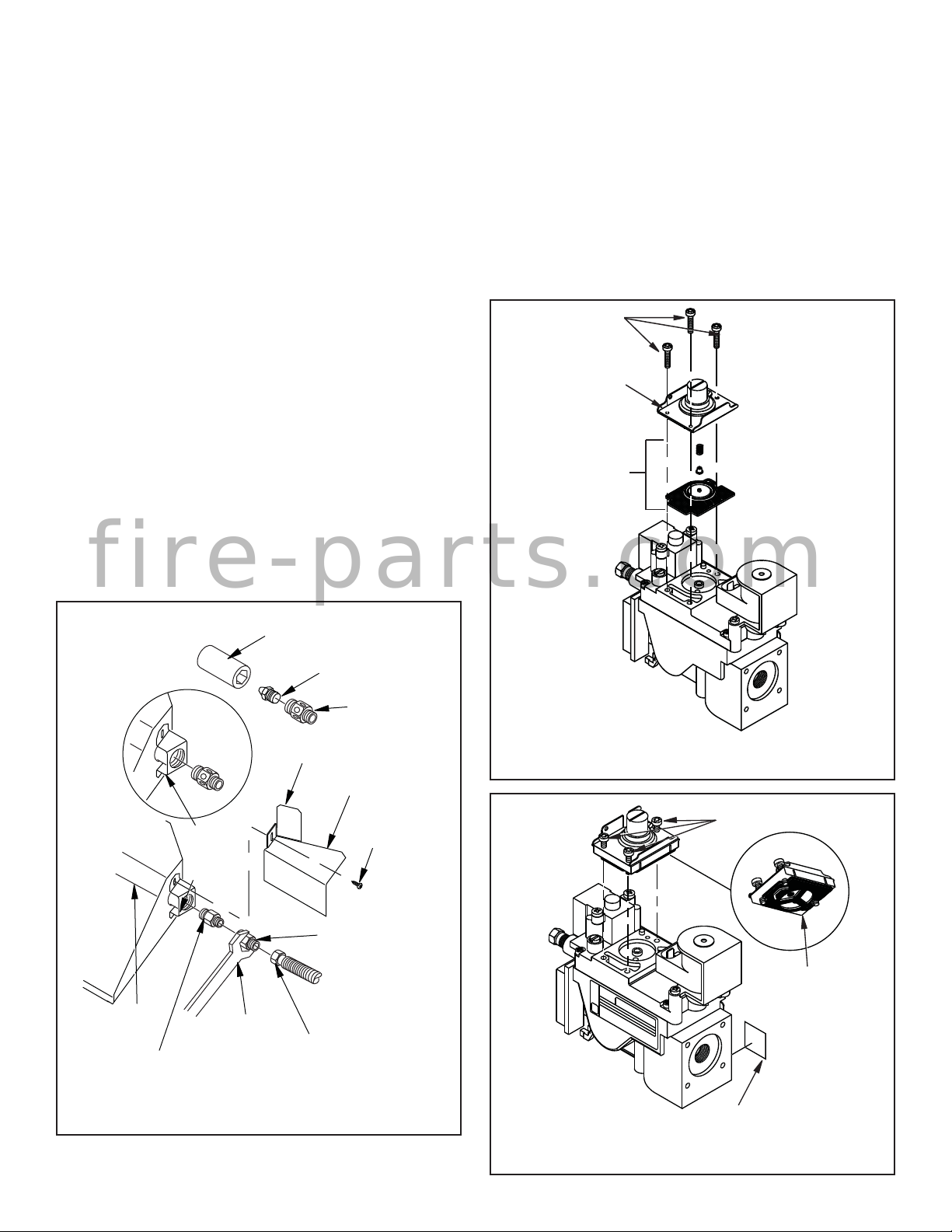
When installing gas components use pipe joint compound or
Teflon tape on all pipe fittings before installing (Do not use pipe
joint compounds on flare fittings).
THE APPLIANCE MUST BE OFF AND COLD BEFORE PERFORMING
THE GAS CONVERSION.
ALL WARNINGS, PRECAUTIONS AND INSTRUCTIONS IN THE INSTAL-
LATION AND OPERATION MANUAL PROVIDED WITH THE APPLIANCE
APPLY TO THESE INSTRUCTIONS.
GENERAL INFORMATION
Gas conversion kits are available to adapt the appliance from the
use of one type of gas to the use of another. These kits contain all
the necessary components needed to complete the task including
labeling that must be affixed to ensure safe operation.
PCBE-325 GAS CONVERSION KIT, ELECTRONIC, NATURAL GAS TO PROPANE/LP GAS
[FOR USE WITH APPLIANCE MODELS BRT2332 AND BRT2532]
PCBE-325 GAS CONVERSION KIT
NATURAL GAS TO PROPANE/LP GAS
P/N 127192-01
Rev. B, 03/2017
HEARTH PRODUCTS
KITS AND ACCESSORIES
Cat. No. Model Description
F1121 PCBE-325 Gas Conversion NG to LP
WARNING
This conversion kit shall be installed by a qualified
service agency in accordance with the manufac-
turer's instructions and all applicable codes and
requirements of the authority having jurisdiction. If
the information in these instructions is not followed
exactly, a fire, explosion or production of carbon
monoxide may result causing property damage,
personal injury or loss of life. The qualified service
agency performing this installation is responsible
for the proper installation of this kit and assumes
responsibility for this conversion. The installation
is not proper and complete until the operation of the
converted appliance is checked as specified in the
manufacturers instructions supplied with the kit.
IMPORTANT LE CANADA SEULEMENT
La conversion devra être effectuée conformément aux
recommandations des autorités provinciales ayant
juridiction et conformément aux exigences du code
d'installation CAN/CSA B149.1.
IMPORTANT CANADA
The conversion shall be carried out in accordance with
the requirements of the provincial authorities having
jurisdiction and in accordance with the requirements
of the CAN/CSA B149.1 Installation code.
AVERTISSEMENT
Cet équipement de conversion sera installé par
une agence qualifiée de service conformément aux
instructions du fabricant et toutes exigences et codes
applicables de l'autorisés avoir la juridiction. Si
l'information dans cette instruction n'est pas suivie
exactement, un feu, explosion ou production de
protoxyde de carbone peut résulter le dommages
causerdepropriété,perteoublessurepersonnellede
vie. L'agence qualifiée de service est esponsable de
l'installation propre de cet équipment. L'installation
n'est pas propre et compléte jusqu'à l'opération de
l'appareil converti est chéque suivant les critères
établis dans les instructions de propriétaire provi-
sionnées avec l'équipement.
1
fire-parts.com

127192-01B2 IHP.us.com
ACCESSING FIREPLACE
You may access burner system through opening in front of unit.
1. Remove front glass panels (if installed). This will keep them from
being damaged. To remove, partially open doors. Press up on upper
spring clip of one door panel with a screwdriver until outer top pivot
pin is free of clip (see Figure 1). Repeat with second door panel.
Place glass panels safely out of your work area.
2. Slide open screens and tuck inside outer pockets on firebox.
IMPORTANT
The burner orifice provided in this kit are only for use at
elevations of 0 to 2,000 feet (610 M) in the USA and 0 to
4,500 feet (0-1372 M) in Canada. At higher elevations
the BTU input must be de-rated by 4% for every 1,000
feet (305 M) to maintain the proper ratio of gas to air. If
the installer must convert the unit to adjust for varying
altitudes, a deration information sticker must be filled
out by the installer and adhered to the appliance at the
time of the conversion. Contact your local gas supplier
for deration requirements for your area.
CAUTION
The gas supply shall be shut OFF prior to discon-
necting the electrical power, before proceeding with
the conversion.
ATTENTION
Avant d’effecteur la conversion, coupez d’abord
l’alimentation en gaz, ensuite, coupez l’alimentation
electrique.
Figure 1 - Removing Glass Doors
Figure 2 - Removing Front Refractory Access Panel
Figure 3 - Removing Log Set
4. Remove logs. Carefully lift top logs straight up until pins are clear
of lower logs (see Figure 3). Continue removing logs one at a time.
The rear log is very heavy and should be lifted with both hands. Place
logs away from your work area. Be careful not to damage logs.
Spring
Clip
Depress Spring Clip to
Release Pivot Pin
Remove Bottom Pin From
Pivot Plate While Sliding Door
Out of the Upper Track Pivot
Plate
Fold Bi-Fold
Door After
Releasing
Spring Clip
and Slide
Door Out
of Upper
Track
3. Remove front refractory access panel by lifting up and angling out
of firebox opening (see Figure 2).
fire-parts.com

IHP.us.com
127192-01B 3
Figure 4 - Removing/Replacing Main Burner Orifice
CONVERSION INSTRUCTIONS
Burner Orifice Conversion
1. Using a #10 short phillips screwdriver, remove top mounting screw
holding pilot burner shield in place (see Figure 4).
2. With orifice mount exposed, use a 7/8” open-end back-up wrench
on 3/8” flare adaptor and remove 3/8” flare fitting at the end of 3/8”
flare adaptor. This will prevent spinning and damage to the flexible
tube (see Figure 4).
3. Using the 7/8” wrench, remove the remaining orifice assembly from
the burner tube.
4. Separate the 3/8” male flare adaptor from the existing natural gas
orifice fitting and save for later reassembly.
5. Thread the propane/LP gas orifice into the propane/LP gas air-mixer
fitting using a 3/8” deep socket driver. NOTE: LP gas airmixer fitting
has six (6) holes. The natural gas fitting has no holes.
6. Applyalightamountofpropane/LPresistantsealanttoboththreaded
ends of LP air-mixer fitting.
7. Thread large threaded end of propane/LP air-mixer fitting into burner
tube and tighten with 7/8” wrench until flange is fully-seated into
bracket.
8. Replace 3/8” flare adaptor onto exposed thread on propane/LP
gas air-mixer fitting. Use 7/8” back-up wrench on fitting to prevent
turning burner tube.
9. Retighten flare fitting on flexible manifold tube with the 3/4” open-
end wrench and 7/8” back-up wrench.
10. Reattach pilot shield onto burner bracket with screw removed in
step 1.
3/8" Deep Socket
Propane/LP
Gas Orifice
Propane/LP
Gas Air-
Mixer Fitting
3/8" Flare Fitting
Natural Gas
Orifice Fitting
Burner
Bracket
Flange
Burner
Tube 7/8" Back-Up
Wrench
Pilot Burner
Shield
#10 Phillips
Screw
3/8" Flare
Adaptor
Gas Control Valve Conversion
Convert the gas control by swapping out the valve regulator portion of
the gas valve.
1. Using a Torx T20 or slotted screwdriver, remove and discard the
three mounting screws, pressure regulator tower, and diaphragm/
spring components (see Figure 5).
2. Ensure that the rubber gasket is properly positioned on the new pres-
sure regulator assembly. Install LP pressure regulator assembly to
valve using the new mounting screws supplied with the kit. Tighten
screws securely (@ approximately 25 in-lbs.) (see Figure 6).
3. Install the identification label enclosed with the gas valve regulator
to the valve body, where it can easily be seen (see Figure 6).
Figure 5 - Removing Mounting Screws, Pressure Regulator
Tower, and Diaphragm/Spring Components
Figure 6 - Installing Pressure Regulator Assembly
Mounting
Screws
Pressure
Regulator
Tower
Diaphragm/
Spring
Components
Mounting
Screws
Rubber Gasket
Identification Label
fire-parts.com

127192-01B4 IHP.us.com
Figure 7 - Applying English and French Conversion Labels
Over Existing Certification Labels on Lighting Instruction Plate
French This Side
English This Side
VENTED GASFIREPLACEHEATER
Conv ersion Kit Model PCD M-36R T
Type of Gas Propane /LP
Minimum Inlet S upply P ressur e11.0" w.c.
For Purpose ofIn put Adjustment
Manifold Pressur "
0
.
0
1
ew.c.
Output R atingMax. 13,000 Btu /h
Input RatingM
ax. 20,000 Btu/h
(0-4500 Ft) Min. 13,000Btu/h
ThisA ppliance is Eq uipped
with an S .I. T.N ova M odel
0.820.651 Valve
Complies with
ANS Z21.88 -2000
CSA 2.33-200 0
Vented Gas Fire place
Heater
116635-01
Previous M ode l #_____________
CUS
Conversion Labeling and Placement
1. Apply the English and French conversion labels over existing certifi-
cation labels (see Figure 7). Existing certification labels are located
on the lighting instruction plate inside the gas valve compartment
area. With permanent ink, print the previous model number on the
label in the space provided (see Figure 8).
2. After filling in the data required on the conversion information label,
affix it to the floor of the appliance where it is easily seen when the
control cover is removed(see Figure 9).
Figure 9 - Conversion Information Label
CONVERSION INFORMATION LABEL
This appliance was converted on
___ - ___ - ___ to ______________ gas
with Kit No. _______________________
by _____________________________
_____________________________
_____________________________
(name and address of organization making
this conversion), which accepts the
responsibility that this conversion has been
properly made.
106080-01
56060
Day Month Year
Lighting
Instruction
Plate
Figure 8 - Print Previous Model Number on
Conversion Labels
Figure 10 - Converting Pilot Orifice
VENTED GAS FIREPLACE
Conversion Kit Model
Type of Gas
Previous Model #
CUS
PILOT ORIFICE CONVERSION
1. Remove the pilot hood assembly from barrel using a 7/16” open
end wrench (see Figure 10).
2. Remove the pilot orifice from inside the barrel with tweezers or a
pair of needle nose pliers.
3. Replace pilot orifice with propane/LP orifice supplied with this kit.
The number 14 is stamped on the sleeve for identification. Insert
the open end of the new pilot orifice into the barrel and thread the
pilot hood back onto the barrel.
4. Tighten the hood using the 7/16” open end wrench until the hood
is fully seated and in-line with the bracket.
IMPORTANT: Be careful not to bend or kink the aluminum tubing
during conversion. Make sure the pilot hood and orifice are properly
mated and aligned after finishing this conversion.
Pilot Hood
Pilot Orifice
Barrel Clip
Pilot Bracket
7/16" Hex
Wrench
fire-parts.com

IHP.us.com
127192-01B 5
Final Preparation
1. Replace any vermiculite and ember material if displaced. Refer to
Ember and Pan Material Placement in owner’s manual.
2. Reinstall logs starting with the rear log, front logs, then remaining
top logs. Refer to Log Placement in owner’s manual.
3. Leak check gas control and any connections you’ve made before
operatingappliance.RefertoGasSupplyHook-upinowner’s manual.
4. Replace refractory access panel and volcanic stone.
5. Replace glassdoorsifpreviouslyinstalled.Referto Installing Optional
Glass Doors in owner’s manual.
6. Using a manometer, test the inlet and manifold gas pressures.
Inspect for proper burner flame appearance (see Figure 11).
The conversion is now complete. To operate your fireplace, refer to
Operating Fireplace in your appliance owner’s manual.
WARNING
Test all gas piping and connections for leaks after
installation or servicing. Correct leaks at once.
WARNING
Never use an open flame to check for a leak. Apply
noncorrosive leak detection fluid to all joints. Bubbles
forming show a leak. Correct all leaks at once.
Figure 11 - Inspect for Proper Burner Flame Appearance
No Blue Flame
Center
Soot at
Flame Tip
Dark Orange
Flame
IMPROPERLY
BURNING FLAME
Soot above
Flame Tip No Soot at
Flame Tip
PROPERLY
BURNING FLAME
Semi-Transparent
Yellow Flame
Blue Flame
Center
REFERENCE INFORMATION
Inlet Gas Supply Pressure
Fuel # Minimum Maximum
Propane 11.0” WC (2.74 kPa) 13.0” WC (3.23 kPa)
Table 1
Manifold Gas Supply Pressure
Fuel # Pressure
Propane Gas 10.0” WC / (2.49 kPa)
Table 2
Main Burner Orifice Sizes
Fireplace Model Drill Size
Propane
BRT2332, BRT2532 #54
Table 3
BTU Input
Models Propane Gas / LP
High Rate Low-rate
BRT2332, BRT2532 25,000 n/a
Table 4
fire-parts.com

127192-01B6 IHP.us.com
______________________________________________________
______________________________________________________
______________________________________________________
______________________________________________________
______________________________________________________
______________________________________________________
______________________________________________________
______________________________________________________
______________________________________________________
______________________________________________________
______________________________________________________
______________________________________________________
______________________________________________________
______________________________________________________
______________________________________________________
______________________________________________________
______________________________________________________
______________________________________________________
______________________________________________________
______________________________________________________
______________________________________________________
______________________________________________________
______________________________________________________
______________________________________________________
______________________________________________________
______________________________________________________
______________________________________________________
______________________________________________________
______________________________________________________
______________________________________________________
______________________________________________________
______________________________________________________
______________________________________________________
______________________________________________________
______________________________________________________
______________________________________________________
______________________________________________________
NOTES
fire-parts.com

IHP.us.com
127192-01B 7
______________________________________________________
______________________________________________________
______________________________________________________
______________________________________________________
______________________________________________________
______________________________________________________
______________________________________________________
______________________________________________________
______________________________________________________
______________________________________________________
______________________________________________________
______________________________________________________
______________________________________________________
______________________________________________________
______________________________________________________
______________________________________________________
______________________________________________________
______________________________________________________
______________________________________________________
______________________________________________________
______________________________________________________
______________________________________________________
______________________________________________________
______________________________________________________
______________________________________________________
______________________________________________________
______________________________________________________
______________________________________________________
______________________________________________________
______________________________________________________
______________________________________________________
______________________________________________________
______________________________________________________
______________________________________________________
______________________________________________________
______________________________________________________
______________________________________________________
NOTES
fire-parts.com

8
Printed in U.S.A. © 2014 Innovative Hearth Products
P/N 127192-01 Rev. B 03/2017
IHP reserves the right to make changes at any time, without notice, in design, materials, specifica-
tions, prices and also to discontinue colors, styles and products. Consult your local distributor
for fireplace code information.
1508 Elm Hill Pike, Suite 108 • Nashville, TN 37210
fire-parts.com
Table of contents
Other IHP Fireplace Accessories manuals
Popular Fireplace Accessories manuals by other brands

Lennox Hearth Products
Lennox Hearth Products BV4000C manual

pleasant hearth
pleasant hearth GALACTICA manual

Valor
Valor L1 Series Nstallation instructions

Sure Heat
Sure Heat RIVERSIDE RS18VFTNG OWNER'S OPERATION AND INSTALLATION MANUAL

Muskoka
Muskoka Sanford MEF253OK Assembly instructions

Dimplex
Dimplex Scottsdale EMP-OSTN-36 install guide

Lennox Hearth Products
Lennox Hearth Products RAD22C-2 installation instructions

Harvia
Harvia WX017 manual

SimpliFire
SimpliFire SF-FORMAT36 Service manual

Montigo
Montigo H38-DF Installing

Empire Comfort Systems
Empire Comfort Systems LK6-1 installation instructions

My Fireplace Blower
My Fireplace Blower BLOT240 installation instructions