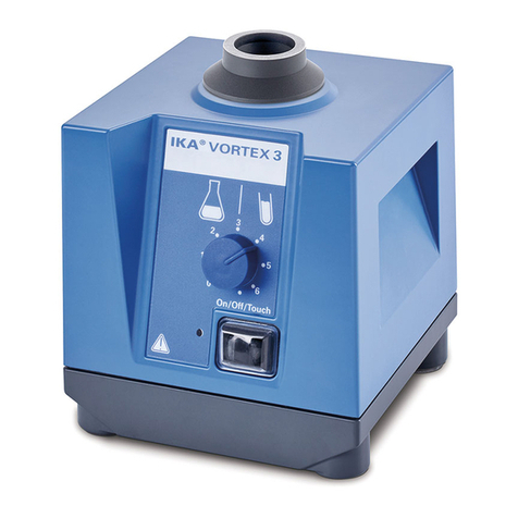
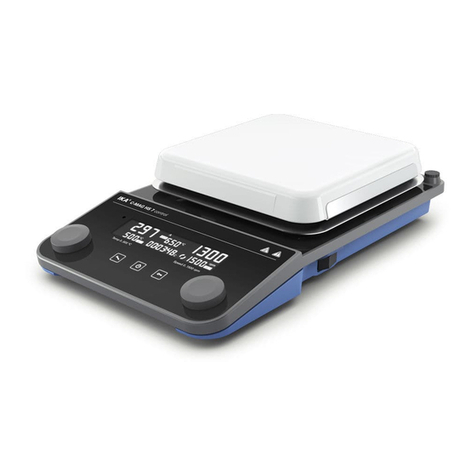
IKA MS 1 User manual

IKA
®
MS1/2 122004
Reg.-No. 4343-01
34 539 00
IKA®WERKE
BETRIEBSANLEITUNG DE 3
OPERATING INSTRUCTIONS EN 11
MODE D’EMPLOI FR 19
INDICACIONES DE SEGURIDAD ES 23
VEILIGHEIDSINSTRUCTIES NL 24
NORME DI SICUREZZA IT 26
SÄKERHETSANVISNINGAR SV 27
SIKKERHEDSHENVISNINGER DA 28
SIKKERHEDSHENVISNINGER NO 29
TURVALLISUUSOHJEET FI 30
γπOδείξεις ασφάλειας EL 31
INSTRUÇÕES DE SERVIÇOPT 33
IKA®MS 1 IKA®MS 2
3453900_BA MS1_MS2_122004 11.04.2005 9:28 Uhr Seite 1

2MS1/2 122004
3453900_BA MS1_MS2_122004 11.04.2005 9:28 Uhr Seite 2

Seite
CE - Konformitätserklärung 3
Sicherheitshinweise 3
Bestimmungsgemäßer Gebrauch 4
Auspacken 4
Wissenswertes 5
Inbetriebnahme 5
Einschalten und Einstellen der Drehzahl
Betriebsart
Aufsätze
Auflagegewicht und Drehzahlbereich
Wartung und Reinigung 7
Zubehör 7
Garantie 8
Technische Daten 8
Ersatzteilliste MS 1 und MS 2 21
Ersatzteilbild MS 1 und MS 2 22
Wir erklären in alleiniger Verantwortung, dass dieses Produkt den
Bestimmungen der Richtlinien 89/336/EG und 73/23/EG entspricht
und mit den folgenden Normen und norminativen Dokumenten
übereinstimmt: DIN EN IEC 61010-1 und DIN EN IEC 61326-1.
•
Der einwandfreie und gefahrlose Betrieb des Gerätes setzt vor-
aus, dass jeder Anwender die Betriebsanleitung gelesen hat und die
enthaltenen Sicherheitshinweise beachtet werden. Bewahren Sie
diese Betriebsanleitung sorgfältig und für jedermann zugänglich auf.
• Der Umgang mit diesem Gerät sollte nur durch entsprechend
geschultes Personal erfolgen, welches das Gerät kennt und be-
rechtigt ist, Arbeiten in diesem Bereich durchzuführen.
• Beachten Sie einschlägige Sicherheitshinweise und Richtlinien,
sowie Arbeitsschutz- und Unfallverhütungsvorschriften für den
Einsatz im Labor.
ACHTUNG! Abdeckungen, bzw. Teile, die ohne Hilfsmittel
vom Gerät entfernt werden können, müssen zum sicheren
Betrieb wieder am Gerät angebracht sein, damit zum Beispiel das
Eindringen von Fremdkörpern, Flüssigkeiten, etc. verhindert wird.
• Der Anwender muss beim Arbeiten mit dem Gerät seine per-
sönliche Schutzausrüstung, entsprechend der Gefahrenklasse des
zu mischenden Mediums wählen und tragen. Bei defekter oder
unangemessener Schutzausrüstung kann der Anwender durch
Spritzen von Flüssigkeiten, Herausschleudern von Teilen oder
Hereinziehen am Schütteltisch, bzw. Aufsatz gefährdet werden.
• Es dürfen keine bewegten Teile
berührt werden (Quetsch-, Stoß-
und Schnittgefahr, siehe Fig. 1:
Gefahrenstelle).
•
Achten Sie darauf, dass Körper-
teile, Haare oder Kleidungsstücke
nicht von bewegten Teilen er-
fasst werden können.
• Das Gerät darf nur auf einem
ebenen, stabilen und rutschfesten Unterbau aufgestellt werden.
• Achten Sie vor Inbetriebnahme darauf, dass der Drehknopf zur
Einstellung der Drehzahl auf Linksanschlag steht, da das Gerät mit
der zuletzt eingestellten Drehzahl zu laufen beginnt.
• Richten Sie Ihre Aufmerksamkeit beim Einstellen der Drehzahl
auf die auf dem Schütteltisch befindlichen Gefäße. Ein mögliches
Herausspritzen des zu schüttelnden Mediums aus den Probege-
fäßen kann dadurch vermieden werden.
• Die für den Schüttelvorgang verwendeten Zubehörteile und auf-
gestellten Gefäße müssen gut befestigt werden. Nicht richtig be-
festigte Schüttelgefäße können beschädigt oder herausgeschleu-
dert werden und Personen gefährden. Die Befestigung der zu
schüttelnden Gefäße sowie die Befestigung der Aufsätze muss in
Sicherheitshinweise
3
MS1/2 122004
Inhaltsverzeichnis
CE-Konformitätserklärung
Fig. 1: Gefahrenstelle
3453900_BA MS1_MS2_122004 11.04.2005 9:28 Uhr Seite 3

regelmäßigen Abständen, und vor allem vor jeder Neuinbetrieb-
nahme, kontrolliert werden.
• Wird ein unruhiger Lauf des Gerätes bemerkt, muss auf jeden
Fall
die Drehzahl soweit reduziert werden, bis keine Laufunruhen
mehr auftreten.
•
Achten Sie darauf, dass einzelne Schüttelgefäße mittig, und meh-
rere Schüttelgefäße gleichmäßig auf dem Schütteltisch platziert
und gut befestigt sind.
•
Beim Schütteln können infolge ungünstiger Beladung und
Schwerpunktlage dynamische Kräfte auftreten, die ein Wandern des
Schüttlers auf der Abstellfläche verursachen können. Ein-
schränkungen der Belastbarkeit, bzw. des Auflagegewichtes bei
hohen Drehzahlen können der Tabelle im Kapitel “Inbetriebnahme”
entnommen werden.
•
Nach einer Unterbrechung der Stromzufuhr während eines
Arbeitsvorganges läuft das Gerät von selbst wieder an.
•
Zusätzliche Gefährdungen für den Anwender können auftreten,
wenn beim Arbeitsvorgang entzündliche Materialien verwendet
werden, oder wenn bei Verwendung von Glaseinrichtungen die
übertragene mechanische Schüttelenergie zum Glasbruch führt.
•
Es dürfen nur Stoffe oder Mischungen von Stoffen mit dem Gerät
bearbeitet werden, von denen der Anwender Kenntnis darüber hat,
dass der Energieeintrag durch das Bearbeiten unbedenklich ist. Das
Gleiche gilt auch für den Energieeintrag durch Sonneneinstrahlung
während des Arbeitsvorganges.
•
Das Gerät darf nicht für den Betrieb in gefährlichen Atmosphären,
zum Mischen von Gefahrstoffen und für den Betrieb unter Wasser
eingesetzt werden.
• Das Zubehör darf nur nach Ziehen des Netzsteckers montiert werden.
•
Der Schutz für den Benutzer ist nicht mehr gewährleistet, wenn
das Gerät mit Zubehör betrieben wird, welches nicht vom Hersteller
geliefert oder empfohlen wird, oder wenn das Gerät in nicht bestim-
mungsgemäßem Gebrauch, entgegen der Herstellervorgabe betrie-
ben wird.
• Das Gerät darf - auch im Reparaturfall - nur von einer Fachkraft geöff-
net werden. Vor dem Öffnen ist der Netzstecker zu ziehen.
Spannungsführende Teile im Inneren des Gerätes können auch län-
gere Zeit nach Ziehen des Netzsteckers noch unter Spannung stehen.
Die Schüttler MS 1 und MS 2 eignen sich durch Verwendung
unterschiedlicher Aufsätze zum Mischen von Flüssigkeiten in
Flaschen, Kolben, Reagenzgläsern, Mikrotiterplatten (nur MS 1)
und Schalen für ein maximales Auflagegewicht von 0,5 kg
(inkl. entsprechendem Aufsatz).
Sie sind für den Einsatz in Laboratorien konzipiert. Die Bewegung
des Schütteltisches, bzw. der aufgestellten Gefäße ist kreisför-
mig. Zum bestimmungsgemäßen Gebrauch muss das Gerät auf
einer stabilen, ebenen und rutschfesten Aufstellfläche stehen.
Außerdem muss darauf geachtet werden, dass sich Gegenstände
nur in ausreichendem Abstand zum Schüttlers befinden dürfen
und diese während des Schüttelvorganges nicht wandern können.
Bitte packen Sie das Gerät vorsichtig aus, und achten Sie auf
Beschädigungen. Es ist wichtig, dass eventuelle Transportschä-
den schon beim Auspacken erkannt werden. Gegebenenfalls ist
eine sofortige Tatbestandsaufnahme erforderlich (Post, Bahn oder
Spedition).
Zum Lieferumfang des Gerätes gehören:
MS 1: Ein Schüttler MS 1, ein Standardaufsatz MS 1.1, ein
Einhandaufsatz MS 1.2, ein Reagenzglaseinsatz MS 1.32, ein
Mikrotiterplatenaufsatz MS 1.4 (siehe auch Zubehör S.6), ein
Netzkabel und eine Betriebsanleitung.
MS 2: Ein Schüttler MS 2, ein Standardaufsatz MS 1.1, ein
Einhandaufsatz MS 1.2 (siehe auch Zubehör S.6), ein Netzkabel
und eine Betriebsanleitung.
4MS1/2 122004
Bestimmungsgemäßer Gebrauch
Auspacken
3453900_BA MS1_MS2_122004 11.04.2005 9:28 Uhr Seite 4

Mit diesem Gerät haben Sie ein qualitativ hochwertiges Produkt
erworben.
Der drehzahlgeregelte Motor ermöglicht ein stufenloses Einstellen
der Drehzahl im Bereich von 0/200 bis 2500 1/min. Die elektroni-
sche Motorregelung hält die eingestellte Drehzahl auch bei
Zunahme des Auflagegewichtes konstant.
Die Schüttler MS 1 und MS 2 sind für Dauerbetrieb geeignet.
Bei längerem Betrieb kann sich das Gehäuse erwärmen.
Die verschiedenen Aufsätze sind einfach auszuwechseln. Sie
könen von der Aufnahme am Gerät nach oben weggezogen wer-
den. Achten Sie beim Aufsetzen auf die richtige Positionierung,
siehe Ersatzteilbild MS 1 und MS 2, S. 22.
Überprüfen Sie, ob die auf dem Typenschild angegebene
Spannung und Frequenz mit der verfügbaren Netzspannung und
Netzfrequenz übereinstimmt. Die verwendete Steckdose muss
geerdet sein (Schutzleiterkontakt).
Wenn diese Bedingungen erfüllt sind, ist das Gerät nach
Einstecken des Netzsteckers betriebsbereit. Andernfalls ist ein
sicherer Betrieb nicht gewährleistet, oder das Gerät kann beschä-
digt werden.
Beachten Sie die in den “Technischen Daten” angegebenen Um-
gebungsbedingungen (Temperatur, rel. Feuchte).
Einschalten und Einstellen der Drehzahl
Der Wippschalter (A) zum Einschalten des Schüttlers befindet sich
an der linken Geräteseite.
In der Mittelstellung “Off” ist das Gerät ausgeschaltet.
Der Drehknopf (B) zur Einstellung der Drehzahl befindet sich front-
seitig, in der Mitte des Gerätes. Die Drehzahl kann im Bereich von
200 bis 2500 1/min stufenlos eingestellt werden. Unterhalb von
200 1/min kann keine Einstellung vorgenommen werden, der
Schüttler steht still.
Im kalten Zustand kann die kleinste einstellbare Drehzahl auch
etwas höher liegen.
Betriebsart einstellen
Touch-Betrieb
Um am Schüttler die Betriebsart Touch-Betrieb einzustellen ist der
Wippschalter (A) auf “Touch” umzulegen. Beim Schüttler MS 1
muss zusätzlich die Wippenarretierung (D) gelöst werden,
Stellung “Touch” wählen. Ist eine Drehzahl ab 200 1/min einge-
stellt kann die Schüttelbewegung durch Druck auf den Aufsatz in
Gang gesetzt werden.
Dauer-Betrieb
Um am Schüttler die Betriebsart Dauer-Betrieb einzustellen ist der
Wippschalter (A) auf “On” umzulegen. Ist eine Drehzahl ab
200
1/min eingestellt beginnt das Gerät sofort zu schütteln. Bei Links-
5
MS1/2 122004
Wissenswertes
Inbetriebnahme
Drehknopf (B)
Wippschalter (A)
Wippenarretierung (D),
nur MS 1
Standardaufsatz (C)
Fig. 2: Bedienelemente
3453900_BA MS1_MS2_122004 11.04.2005 9:28 Uhr Seite 5

anschlag des Drehknopfes (B) steht der Schüttler zunächst still
und die gewünschte Drehzahl kann anschließend eingestellt wer-
den. Beim Schüttler MS 1 kann zusätzlich die Wippenarretierung
(D) gesetzt werden, Stellung “Platform” wählen.
Aufsätze
Um ein sicheres Arbeiten zu gewährleisten müssen die von IKA
empfohlenen Aufsätze auf dem Schütteltisch gut befestigt sein.
Außerdem dürfen die angegebenen Gewichts- und Drehzahl-
bereiche nicht überschritten werden.
MS 1.1 Standardaufsatz
Dieser Aufsatz dient zum Aufsetzen und
Schütteln von Röhrchen und anderen kleinen
Gefäßen bis zu einem Durchmesser von 30 mm.
Eine Mulde verhindert das Abrutschen der
Gefäße. Für Arbeiten im Touch-Betrieb.
MS 1.2 Reagenzglaseinsatz
Dieser Aufsatz besteht aus der MS 1.3
Reagenzglasaufnahme und dem MS 1.21
Einhandeinsatz.
MS 1.21 Einhandeinsatz
Schaumstoffeinlage zum Einsetzen in die
MS 1.3 Reagenzglasaufnahme. Im Dauerbetrieb,
bei niedriger Drehzahl können flache Behälter wie
z.B. Petrischalen oder Kulturflaschen geschüttelt
werden. Sind größere und höhere Gefäße, z.B. Erlenmeyerkolben
zu schütteln müssen die Gefäße festgehalten werden. Auch für
das Arbeiten im Touch-Betrieb ist dieser Einsatz geeignet.
MS 1.3 Reagenzglasaufnahme
Dieser Aufsatz kann verschiedene Einsätze auf-
nehmen. Es sind Arbeiten im Dauer-Betrieb, wie
auch im Touch-Betrieb möglich.
Die Einsätze sind im Folgenden beschrieben:
MS 1.31 Reagenzglaseinsatz
Schaumstoffeinlage zum Einsetzen in die MS 1.3
Reagenzglasaufnahme. Dieser Einsatz kann max. 14
Reagenzgläser mit einem Durchmesser von 8 mm
aufnehmen. Für Arbeiten im Dauer-Betrieb.
MS 1.32 Reagenzglaseinsatz
Schaumstoffeinlage zum Einsetzen in die MS 1.3
Reagenzglasaufnahme. Dieser Einsatz kann max. 6
Reagenzgläser mit einem Durchmesser von
10 mm aufnehmen. Für Arbeiten im Dauer-Betrieb.
MS 1.33 Reagenzglaseinsatz
S
chaumstoffeinlage zum Einsetzen in die MS 1.3
Reagenzglasaufnahme. Dieser Einsatz kann max. 4
Reagenzgläser mit einem Durchmesser von
15 mm aufnehmen. Für Arbeiten im Dauer-Betrieb.
MS 1.34 Reagenzglaseinsatz
Schaumstoffeinlage zum Einsetzen in die MS 1.3
Reagenzglasaufnahme. In diesen Einsatz können
beliebige Bohrungen angebracht werden. Für
Arbeiten im Dauer-Betrieb.
MS 1.4 Mikrotiterplattenaufsatz
Dieser Aufsatz ermöglicht die Aufnahme einer
Mikrotiterplatte.
Auflagegewicht und Drehzahlbereiche
Die Schüttler MS 1 und MS 2 sind für ein max. Auflagegewicht
von 0,5 kg (inkl. Aufsatz) konzipiert. Für die entsprechenden
Aufsätze sind im Folgenden sinnvolle, maximale Drehzahlen ange-
geben. Diese Angaben stellen aber nur Richtwerte dar. Der
Anwender hat in jedem Fall dafür zu sorgen, dass ein sicherer
Betrieb gewährleistet ist.
Durch langsames Hochfahren
der
Drehzahl muss der Anwender die Grenzdrehzahl für die bestehen-
den Gegebenheiten herausfinden. Werden diese Grenzen über-
6MS1/2 122004
3453900_BA MS1_MS2_122004 11.04.2005 9:29 Uhr Seite 6

schritten, so können die zu schüttelnden Medien aus den Gefäßen
austreten oder herausgeschleudert werden. Bei Mikrotiteran-
wendungen kann eine zu hohe Drehzahl dazu führen, dass sich
Proben aus verschiedenen Kammern miteinander vermischen.
Desweiteren können bei zu hohen Drehzahlen Gefäße von den
Einsätzen herunterrutschen oder aus ihnen heraus geschleudert
werden.
Max. Drehzahl Touch- Dauer-
[1/min] Betrieb betrieb
MS 1.1 2500 ja nein
Standardaufsatz
MS 1.2 1400 ja ja
Einhandaufsatz
MS 1.3 1400 nein ja
Reagenzglasaufnahme
mit Einhandeinsätzen
MS 1.4 800 nein ja
Mikrotiterplattenaufsatz
Wird der Schüttler mit seiner Umgebung verschraubt (d.h. in eine
Anlage eingebaut), ist im Betrieb darauf zu achten, dass infolge
ungünstiger Beladung und Schwerpunktlage dynamische Kräfte
auftreten, die zum Einen die Umgebung in Schwingung versetzen
kann, oder den Tisch zu unkontrollierbaren Schwingungen anregt.
Wird ein unruhiger Lauf des Gerätes bemerkt , muss auf jeden Fall
die Drehzahl soweit reduziert werden, bis keine Laufunruhen
mehr auftreten
.
Die Schüttler MS 1, bzw. MS 2 arbeiten wartungsfrei. Sie unter-
liegen lediglich der natürlichen Alterung der Bauteile und deren
statistischer Ausfallrate.
Bei Eratzteilbestellungen geben Sie bitte die auf dem Typenschild
angegebene Fabrikationsnummer, den Gerätetyp sowie die
Positionsnummer und die Bezeichnung des Ersatzteiles an.
Bitte senden Sie nur Geräte zur Reparatur ein, die gereinigt und
frei von gesundheitsgefährdenden Stoffen sind. Wenn Sie mit
gesundheitsgefährdenden oder gefährlichen Stoffen gearbeitet
haben, informieren Sie uns bitte darüber.
Reinigen Sie IKA-Geräte nur mit von IKA freigegebenen
Reinigungsmitteln. Verwenden Sie zum Reinigen von:
Farbstoffen: Isopropanol
Baustoffen: Tensidhaltiges Wasser/ Isopropanol
Kosmetika: Tensidhaltiges Wasser/ Isopropanol
Nahrungsmittel: Tensidhaltiges Wasser
Brennstoffe: Tensidhaltiges Wasser/ Isopropanol
Bei nicht genannten Stoffen fragen Sie bitte bei IKA nach. Tragen
Sie zum Reinigen der Geräte Schutzhandschuhe. Elektrische
Geräte dürfen zu Reinigungszwecken nicht in das Reinigungs-
mittel gelegt werden.
Bevor eine andere als die vom Hersteller empfohlene Reinigungs-
oder Dekontaminierungsmethode angewandt wird, hat sich der
Benutzer beim Hersteller zu vergewissern, dass die vorgesehene
Methode das Gerät nicht zerstört.
Bezeichnung Beschreibung Ident- Nr. MS 1 MS 2
MS 1.1 Für Röhrchen und kleine L001260 X X
Standardaufsatz Gefäße bis
ø
30 mm
MS 1.2 Bestehend aus MS 1.3 L001900 X X
Einhandaufsatz
MS 1.3 Aufsatz für die Einsätze L001490 X X
Reagenzglasaufnahme
MS 1.21, MS 1.31, MS 1.32,
MS 1.33, MS 1.34
MS 1.4 Für eine Mikrotiterplatte L001280 X -
Mikrotiterplattenaufsatz
MS 1.21 Für Gefäße mit flachem L001540 X X
Einhandeinsatz Boden
7
MS1/2 122004
Wartung und Reinigung
Zubehör
3453900_BA MS1_MS2_122004 11.04.2005 9:29 Uhr Seite 7

MS 1.31 Für 14 Gefäße L001840 X X
Reagenzglaseinsatz mit ¢ 8 mm
MS 1.32 Für 6 Gefäße L001850 X X
Reagenzglaseinsatz mit ¢ 10 mm
MS 1.33 Für 4 Gefäße L001860 X X
Reagenzglaseinsatz mit ¢ 15 mm
MS 1.34 Zum Anbringen beliebiger L001830 X X
Reagenzglaseinsatz Bohrungen
Sie haben ein Original IKA-Laborgerät erworben, das in Technik
und Qualität höchsten Ansprüchen gerecht wird.
Entsprechend den IKA-Verkaufs-und Lieferbedingungen beträgt
die Gewährleistungszeit 24 Monate. Im Gewährleistungsfall wen-
den Sie sich bitte an Ihren Fachhändler. Sie können aber auch das
Gerät unter Beifügung der Lieferrechnung und Nennung der Re-
klamationsgründe direkt an unser Werk senden. Frachtkosten
gehen zu Ihren Lasten.
Die Gewährleistung erstreckt sich nicht auf Verschleißteile und gilt
nicht für Fehler, die auf unsachgemäße Handhabung und unzurei-
chende Pflege und Wartung, entgegen den Anweisungen in die-
ser Betriebsanleitung, zurückzuführen sind.
Senden Sie im Servicefall das Gerät in der Originalverpackung
zurück. Lagerverpackungen sind für den Rückversand nicht aus-
reichend. Verwenden Sie zusätzlich eine geeignete Transport-
verpackung.
Bemessungsspannung: VAC 230±10%
oder VAC 115±10%
Frequenz: Hz 50/60
Aufnahmeleistung: W 31
Abgabeleistung: W 10
Drehzahl: 1/min 0 - 2500 (stufenlos
einstellbar ab 200)
Einstellung der Schüttelfrequenz: analog (stufenlos)
Netzanschluss nach IEC 60 320: Kaltgerätestecker mit
Sicherungen
Sicherungen: mA 2 x 400T (230V)
Ident-Nr. L001060
(im Kaltgerätestecker) 2 x 630T (115V)
Ident-Nr. 2008600
Netzkabel: mit Schutzleiter und ent-
sprechend der Länder-
spezifikation
Drehzahlanzeige: Skala 0 - 2500
Antrieb: Drehzahlgeregelter Gleich-
strommotor, kugelgelagert
Schutz bei Überlast: Temperaturfühler in
Motorwicklung
Schüttelhub mm 4,5
Schüttelbewegung: kreisförmig
Zul. Einschaltdauer: % 100
Zul. Umgebungstemperatur: °C +5 bis +40
Zul. relative Feuchte: % 80
Schutzart nach DIN EN 60 529: IP 21
Schutzklasse: I
Überspannungskategorie: II
Verschmutzungsgrad: 2
Geräteeinsatz über NN m max. 2000
Max. Beladung inkl. Aufsatz: kg 0,5
Abmessungen: (B x T x H) mm 115 x 225 x 60
Gewicht ohne Beladung: kg 3,5
8MS1/2 122004
Technische Daten
Garantie
3453900_BA MS1_MS2_122004 11.04.2005 9:29 Uhr Seite 8

where they can be accessed by everyone.
• Only staff who have been trained accordingly, know the applian-
ce and are authorised to carry out work in this field should use this
appliance.
• Please follow the relevant safety instructions and guidelines, and
occupational health and safety regulations for use in the labora-
tory.
Note! Covering or parts that are capable of being removed
from the unit without accessory equipment have to be
reattached to the unit for safe operation in order to prevent, for
example, the ingress of fluids, foreign matter, etc..
• When working with the shaking unit, the user must select and
wear his personal protective equipment according to the mixing
hazard category of the medium. Defective or inappropriate protec-
tive equipment can expose the user to the risk of spurting liquids,
projectile parts or being pulled in at the shaking table or support.
• Never touch moving parts (risk
of crushing, impact and cutting,
see fig.1: point of danger)!
• Ensure that parts of the body,
hair or items of clothing cannot
be trapped by the moving parts.
• Always install the appliance on
a flat, stable non-slip base.
• Before use, please ensure that
the knob for setting the speed is at the left stop as the appliance
starts up at the last speed which was set.
• Pay attention to the vessels on the shaking table when setting
the speed. This will prevent any of the medium to be shaken from
spurting out of the sample vessels.
•
All accessories and vessels in place for the shaking process must
be firmly secured. Shaking vessels which are not properly secured
could get damaged or be projected out, thus causing injury. It is
essential to regularly check that the vessels to be shaken and the
attachments are firmly secured, especially before using the applian-
ce again.
• If you notice that the device is not running smoothly, the speed
Page
Declaration of CE-conformity 9
Safety instructions 9
Correct use 10
Unpacking 10
General information 11
Commissioning 11
Switching on and setting of the speed
Operation mode
Attachments
Supported weight and speed range
Maintenance and Cleaning 13
Accessories 13
Warranty 14
Technical data 14
List of spare parts MS 1 and MS 2 21
Spare parts diagram MS 1 and MS 2 22
We declare under our sole responsibility that this product corros-
ponds to the regulations 89/336/EG and 73/23/EG and conforms
with the standards or standardized documents
DIN EN IEC 61010-1
and DIN EN IEC 61326-1.
• In order to be able to use the appliance properly and safely, every
user must first read the operating instructions and observe the
safety instructions contained therein.
Take care of these operating instructions and keep them in a place
9
MS1/2 122004
Contents
Safety instructions
Declaration of CE-conformity
Fig. 1: point of danger
3453900_BA MS1_MS2_122004 11.04.2005 9:29 Uhr Seite 9

must always be reduced until no more uneveness occurs in the
operation.
•
Please make certain that individual agitation containers are pla-
ced in the middle of the agitation table and that if several contai-
ners are placed on the agitation table together, they are evenly
distributed and well secured.
•
Because of improper loading an the position of the center of gra-
vity, dynamic forces may arise during the shaking process that
cause the shaker to move about the table. For limits on the load or
the weight placed on the agitation table at high speed, please refer
to the table in the chapter „Commissioning“.
• The appliance starts up again automatically following a cut in the
power supply during a work process.
• The user may also be at risk if inflammable materials are used in
the work process or if the transmitted mechanical power causes
any glass equipment in use to break.
• The device may only be used to process those materials or mate-
rial mixtures that the user knows will not react dangerously to the
extra energy produced by processing. This also applies to extra
energy generated by means of solar radiation during the work
process.
• The shaking unit may not been used in explosive atmospheres,
for mixing dangerous substances or under water.
• Accessories may only be assembled once the plug has been dis-
connected.
• The safety of the user cannot be guaranteed if the appliance is
operated with accessories that are not supplied or recommended
by the manufacturer or if the appliance is operated improperly con-
trary to the manufacturer’s specifications.
The machine may only be opened by trained specialists - even
during repairs. The machine is to be unplugged from the mains
before opening. Live parts inside the machine may still be live for
some time after unplugging from the mains.
The shakers MS 1 and MS 2
are suitable for usage in various
attachments for mixing liquids in
e.g. bottles, flasks, test tubes,
microtiter plates (only MS 1) and bowls for a maximum supported
load of 0.5 kg (incl. the suitable attachment).
They are designed for use in laboratories.
The motion of the agi-
tation table or of the containers placed on it is circular.
For usage in accordance with requirements, the machine must be
standing on a stable, even surface that is slipfree. In addition, care
must be taken that objects in the vicinty are a sufficient distance
away from the shaking unit and that they will not come too close
to the shaking unit while it is in operation.
Please unpack the equipment carefully and check for any dama-
ges. It is important that any damages which may have arisen
during transport are ascertained when unpacking. If applicable a
fact report must be set immediately (post, rail or forwarder).
The delivery scope covers:
MS 1: A shaker MS 1, a standard attachment MS 1.1, a one-hand
attachment MS 1.2, a test tube insert MS 1.32, a microtiter plate
attachment MS 1.4 (also see p. 6, accessories), a mains cable and
an operating instructions.
MS 2: A shaker MS 2, a standard attachment MS 1.1, a one-hand
attachment MS 1.2 (also see p. 6, accessories), a mains cable and
an operating instructions.
10 MS1/2 122004
Correct use
Unpacking
3453900_BA MS1_MS2_122004 11.04.2005 9:29 Uhr Seite 10

With the purchase of this device, you have acquired a high-
quality product.
The speed-controlled motor allows for infinity speed adjustment
in the range from 0/200 to 2500 rpm. Electronic motor
control holds the set speed constant even if the weight of the
material on the surface increases.
The shaker MS 1 und MS 2 are suitable for continuous operation.
The casing may heat up when the apliance is in use for a prolon-
ged time.
The various attachments can be changed easily by pulling them up
off the receptacle on the appliance. Ensure that the attachment is
positioned correctly when fitting. see spare parts diagram
MS 1 and MS 2
, p. 22.
Check whether the voltage specified on the type plate matches
the mains voltage available. The power socket used must be
earthed (protective earth conductor contact). If these conditions
are met, the device is ready to operate after plugging in the
mains plug. If these procedures are not followed, safe operation
cannot be guaranteed and/or the equipment may be damaged.
Observe the ambient conditions (temperature, humidity, etc.)
listed under “Technical Data”.
Switching on and adjustment of speed
The rocker switch (A) for switching on the shaker is on the left of
the appliance.
The appliance is switched off in the centre position ”off”.
The knob (B) for setting the speed is on the front of the applian-
ce in the centre. The speed can be continuously adjusted within a
range of 200 to 2500 rpm.
The shaker cannot be set below 200 rpm as it will be at a standstill.
When cold, the lowest possible speed may be slightly higher.
Adjustment of the operation mode
Touch operation mode
To set the shaker to touch mode, set the rocker switch (A) to
”Touch”. You must also release the rocker catch (D) on shaker
MS 1: select the ”Touch” position. If the speed is set to 200 rpm
or higher, you can start the shaking process by pressing on the
attachment.
Continuous operation mode
To set the shaker to continuous mode, set the rocker switch (A) to
”On”. If the speed is set to 200 rpm or higher, the appliance will
begin to shake immediately. When the knob (B) is at the left stop,
the shaker will initially stand still, allowing you to set the required
speed. You can also set the rocker catch (D) for shaker MS 1:
select the ”platform” position.
11
MS1/2 122004
General information
Commissioning
Knob (B)
Rocker switch (A)
Rocker catch (D),
only MS 1
Standard attachment (C)
Fig. 2: Operating elements
3453900_BA MS1_MS2_122004 11.04.2005 9:29 Uhr Seite 11

12 MS1/2 122004
Attachments
Attachments recommended by IKA must be connected to the agi-
tation table to ensure safe operation. In addition, the usable weight
and speed range must not be exceeded.
MS 1.1 Standard attachment
This attachment is used to attach and shake tubes
and other small vessels of diameter up to 30 mm.
A trough prevents the vessels from slipping. For
work in touch mode.
MS 1.2 Test tube insert
This attachment comprises the MS 1.3 test tube
attachment and the MS 1.21 one-hand insert.
MS 1.21 One-hand insert
Foam inlay for inserting into MS 1.3 test tube
attachment. Flat containers such as Petri dishes or
culture bottles can be shaken at a slow shaking
rate in continuous mode. Any larger or taller ves-
sels you may wish to shake, for example Erlenmeyer flasks, must
be held in place. This insert is also suitable for working in ”touch
mode”.
MS 1.3 Test tube attachment
This attachment can hold various inserts. It is pos-
sible to work in both continuous mode and touch
mode. The inserts are described below:
MS 1.31 Test tube insert
Foam inlay for inserting into MS 1.3 test tube attach-
ment. This insert can hold up to 14 test tubes with a
diameter of 8 mm. For work in continuous mode.
MS 1.32 Test tube insert
Foam inlay for inserting into MS 1.3 test tube attach-
ment. This insert can hold up to 6 test tubes with a
diameter of 10 mm. For work in continuous mode.
MS 1.33 Test tube insert
Foam inlay for inserting into MS 1.3 test tube attach-
ment. This insert can hold up to 4 test tubes with a
diameter of 15 mm. For work in continuous mode.
MS 1.34 Test tube insert
Foam inlay for inserting into MS 1.3 test tube attach-
ment. You can make as many holes as you like in this
insert. For work in continuous mode.
MS 1.4 Microtiter plate attachment
This attachment is used to hold a microtiter
plate.
Supported load and speed range
Shakers MS 1 and MS 2 are designed for a max. load of 0.5 kg
(incl. attachment). The recommended maximum speeds for the
respective attachments are specified below. These values are,
however, only guidelines. The user must always ensure a safe
operation. The user must determine the limit speed for the exi-
sting conditions by gradually increasing the speed. If these limits
are exceeded, the media to be shaken may escape or be projec-
ted out of the vessels. With microtiter applications, excessive
speed can cause samples from different chambers to get mixed
together. Furthermore, excessive speed can cause vessels to
slide off or be projected out of the inserts.
3453900_BA MS1_MS2_122004 11.04.2005 9:29 Uhr Seite 12

13
MS1/2 122004
Max. speed Touch- Continuous
[rpm] operation mode operation mode
MS 1.1 2500 yes no
Standard attachment
MS 1.2 1400 yes yes
One-hand attachment
MS 1.3 1400 no yes
Test tube attachment with
one-hand insert
MS 1.4 800 no yes
Microtiter plate attachment
If the shaker is screwed down (i.e. built into a system), please
note that dynamic forces can be generated during operation as a
result of unfavourable loading and a poor centre of gravity positi-
on. This could cause the surrounding area to vibrate or induce
uncontrollable vibrations in the table. If you notice that the appli-
ance is not running smoothly, reduce the speed until it runs smoo-
thly again.
The shaker MS 1 and MS 2 are maintenance-free. It is sub-
ject only to the natural wear and tear of components and their sta-
tistical failure rate.
When ordering spare parts, please give the manufacturing
number shown on the type plate, the machine type and the
name of the spare part.
Please send in equipment for repair only after it has been cleaned
and is free from any materials which may constitute a health
hazard. Please tell us if you have used any materials which are
dangerous or which may constitute a health hazard.
Use only cleansing agents which have been approved by IKA
to clean IKA devices.
To remove use:
Dyes isopropyl alcohol
Construction materials water containing tenside/
isopropyl alcohol
Cosmetics water containing tenside/
isopropyl alcohol
Foodstuffs water containing tenside
Fuels water containing tenside
For materials which are not listed, please request information from
IKA. Wear the proper protective gloves during cleaning of the
devices. Electrical devices may not be placed in the cleansing
agent for the purpose of cleaning.
Before using another than the recommended method for cleaning
or decontamination, the user must ascertain with the manufactu-
rer that this method does not destroy the instrument.
Designation Description Id-No. MS 1 MS 2
MS 1.1
For small tubes and vessels
L001260 X X
Standard attachment
upto diameter 30 mm
MS 1.2 Consisting of MS 1.3 L001900 X X
One-hand attachment and MS 1.21
MS 1.3 Attachment for inserts L001490 X X
Test tube attachment
MS 1.21, MS 1.31, MS 1.32,
MS 1.33, MS 1.34
MS 1.4 For microtiter plate L001280 X -
Microtiter plate attachment
MS 1.21 For vessels with flat L001540 X X
One-hand insert base
MS 1.31 For 14 vessels L001840 X X
Test tube insert with diameter 8 mm
MS 1.32 For 6 vessels L001850 X X
Test tube insert with diameter 10 mm
MS 1.33 For 4 vessels L001860 X X
Test tube insert with diameter 15 mm
MS 1.34 For any number of L001830 X X
Test tube insert bore holes
Maintenance and cleaning
Accessories
3453900_BA MS1_MS2_122004 11.04.2005 9:29 Uhr Seite 13

14 MS1/2 122004
You have purchased an original IKA laboratory machine which
meets the highest engineering and quality standards.
In accordance with IKA warranty conditions, the warranty period is
24 months. For claims under the warranty please contact your
local dealer. You may also send the machine direct to our works,
enclosing the delivery invoice and giving reasons for the claim. You
will be liable for freight costs.
The warranty does not cover wearing parts, nor does it apply to
faults resulting from improper use or insufficient care and
maintenance contrary to the instructions in this operating manual.
If you require servicing, return the appliance in its original packa-
ging. Storage packaging is not sufficient. Please also use suitable
transport packaging.
Design voltage: VAC 230±10%
oder VAC 115±10%
Design frequency: Hz 50/ 60
Input power: W 31
Output power W 10
Shaking rate: rpm 0 - 2500 (infinitely
adjustable from 200)
Speed adjustment:
analog (infinitely)
Power supply acc. to IEC 60320:
cold device plug
with fuses
Fuses: mA 2 x 400T (230V)
Ident-Nr. L001060
(in cold device plug) 2 x 630T (115V)
Ident-Nr. 2008600
Mains cable: with ground wire and in
compliance with country
spezification
Shaking rate display: Scale 0 - 2500
Drive: Speed controlled DC-
motor, with ball bearings
Protection at overloaded: Temperature sensor in
motor winding
Agitation stroke: mm 4.5
Shaking motion: circular
Perm. duration of operation: % 100
Perm. ambient temperature: °C +5 bis +40
Perm. relative humidity: % 80
Protection type acc. to DIN EN 60 529:
IP 21
Protection class: I
Overvoltage category: II
Contamination level: 2
Operation at a terrestrial attitude:
mmax. 2000
Max. supported load incl. attachment:
kg 0,5
Dimernsions: (W x D x H) mm 115 x 225 x 60
Weight without supported load: kg 3.5
Technical data
Warranty
3453900_BA MS1_MS2_122004 11.04.2005 9:29 Uhr Seite 14

Page
Déclaration de conformité CE 15
Conseils de sécurité 15
Utilisation conforme 16
Déballage 16
Paticularités intéressantes 17
Mise en service 17
Mise en marche et réglage de la vitesse de rotation
Mode de fonctionnement
Supports
Poids de charge et plage de la vitesse de rotation
Entretien et nettoyage 19
Accessories 19
Garantie 20
Caractéristiques techniques 20
Catalogue des pièces de rechange MS 1 et MS 2 21
Tableau des pièces de rechange MS 1 et MS 2 22
Nous déclarons sous notre propre responsabilité que se produit
est conforme aux réglementations 89/336/EG et 73/23EG et en
conformité avec les normes ou documents normalisés suivant
DIN EN IEC 61010-1 et DIN EN IEC 61326-1.
• Pour assurer une utilisation correcte et sans danger de l’appareil,
chaque utilisateur doit avoir lu le mode d’emploi et les consignes
de sécurité doivent être respectées. Conservez ce mode d’emploi
avec soin et de manière à ce qu’il soit accessible à tous.
• L’appareil ne doit être manipulé que par du personnel spéciale-
ment formé connaissant l’appareil et autorisé à exécuter des tra-
vaux dans ce domaine.
• Veuillez observer les consignes de sécurité et directives appli-
cables, de même que les prescriptions relatives à la protection du
travail et à la prévention des accidents en cas d’utilisation au labo-
ratoire.
ATTENTION! Les couvercles et/ ou pièces pouvant être dé-
tachées sans outil de l'appareil, doivent être obligatoirement
remis en place pour garantir un fonctionnement sûr de l'appareil.
Ceci permet d'éviter la pénétration de corps étrangers, de liquides,
etc..
• L’utilisateur doit choisir et porter l’équipement de protection indi-
viduelle en fonction de la classe de danger du milieu. En cas d’é-
quipement de protection défectueux ou inadapté, l’utilisateur ris-
que d’être exposé à des projections de liquides, l’éjection de piè-
ces ou le happement par la tableà secousses ou le support.
• Ne touchez pas les pièces en
mouvement (risque d’écrase-
ment, de coups et de coupure,
voir fig. 1: emplacement dange-
reux)!
• Attention au parties du corps,
cheveux ou vêtements qui ris-
quent d’être happés par les
pièces mobiles.
• Veillez à placer l’appareil sur un support plan, stable et non glissant.
• Vérifiez avant la mise en service que le bouton rotatif de réglage
de la vitesse de rotation soit sur la butée gauche, car l’appareil
commence à tourner sur la dernière vitesse de rotation réglée.
• Lors du réglage de la vitesse de rotation, veillez au récipients se
trouvant sur la table à secousses. Ceci pour éviter d’asperger le
liquide se trouvant dans les éprouvettes.
• Les accessoires utilisés dans les processus d’agitation et les réci-
pients placés doivent être bien fixés. Les récipients mal fixés peu-
vent être endommagés ou projétes et blesser les personnes pré-
sentes. La fixation des récipients à sécouer et celles de supports
15
MS1/2 122004
Conseils de sécurité
Sommaire
Déclaration de conformité CE
Fig. 1: emplacement dangereux
3453900_BA MS1_MS2_122004 11.04.2005 9:29 Uhr Seite 15

doivent se faire à intervalles réguliers et, surtout, être controlées
avant chaque nouvelle mise en service.
•
En cas de fonctionnement bruyant et irrégulier, réduisez la vites-
se de rotation de l’appareil jusqu’à disparition du phénomène.
• Vérifiez le bon positionnement des récipients: au centre si vous
utilisez peu de récipients, sinon de manière uniforme sur la surfa-
ce de la table.
•
Durant l’agitation, si le chargement et la position du centre de
gravité sont incorrects, des forces dynamiques entraînent le dépla-
cement de l’agitateur vibrant sur la table. Reportez-vous au tableau
du chapitre „Mise en service“ plus de renseignements sur les
restrictions de chargement (ou du poids de charge) à hautes vites-
ses de rotation.
•
Après une coupure de l’alimentation électrique pendant une
opération, l’appareil redémarre seul.
•
Des dangers supplémentaires pour l’utilisateur peuvent apparaît-
re lorsque des matériels inflammables sont employés ou en cas
d’utilisation de dispositifs en verre lorsque l’énergie mécanique
transmise conduit au bris du verre.
•
Ne peuvent être transformés avec l’appareil que les matières ou
mélanges de matières dont l’utilisateur sait que le transfert d’én-
ergie est sans danger lors de l’opération. Le même principe s’ap-
plique à l’arrivée d’énergie par rayonnement solaire pendant
l’opération.
•
L’appareil ne doit pas être utilisé dans des environnements
exposés aux explosions, pour le mélange de matières dangereu-
ses ni sous l’eau.
•
Les accessoires ne peuvent être montés qu’une fois la prise sec-
teur débranchée.
•
La protection de l’utilisateur n’est plus garantie si l’appareil est
utilisé avec un accessoire n’ayant pas été fourni ou conseillé par le
fabricant ou si l’appareil est utilisé de manière non conforme aux
prescriptions du fabricant.
•
L’appareil ne doit être ouvert, même en cas de réparation, que
par le personnel spécialisé. Il faut débrancher la prise secteur
avant l’ouverture. Les éléments sous tension à l’intérieur de l’ap-
pareil peuvent encore l’être longtemps après le débranchement
de ce dernier.
Les agitateur MS 1 et MS 2, grâce à l’utilisation de différents sup-
ports, conviennent pour le mélange de liquides dans des bouteil-
les, ballons, tubes à essais, plaque de microtitration (seulement
MS 1) et cuvettes, avec un poids de chargement maximal de 0,5
kg (inclu supports correspondants).
Il peut être utilisé en laboratoire. Le mouvement de la table à
secousses et des récipient qui y sont posés est circulaire.
Pour une utilisation conforme, l’appareil doit être posé sur une sur-
face stable, plane et non glissante.
Veillez par ailleurs à ce que les objets situés à côté de l’agitateur
se trouve à bonne distance et ne puissrnt pas se déplacer pendant
l’agitation.
Déballez l'appareil avec précaution et vérifiez s'il est en parfait
état. Il est important de constater les éventuels dommages dus au
transport dès le déballage. Le cas échéant, établir immédiatement
un constat correspondant (poste, chemins de fer ou transporteur).
Le volume de livraison de l'appareil comprend:
MS 1: Un agitateur MS 1, un support standard MS 1.1, un insert
MS 1.2, un portoir pour tubes à essais MS 1.32, un plateau pour
plaque de microtitration MS 1.4 (aussi voir p.6, accessoires), une
câble de réseau et le mode d'emploi.
MS 2: Un agitateur MS 2,un support standard MS 1.1, un insert
MS 1.2 (aussi voir p.6, accessoires)), une câble de réseau et le
mode d'emploi.
16 MS1/2 122004
Utilisation conforme
Déballage
3453900_BA MS1_MS2_122004 11.04.2005 9:29 Uhr Seite 16

Avec cet appareil, vous avez acquis un produit de grande qualité.
Le moteur à réglage de la vitesse de rotation permet un
réglage en continu de la fréquence d’agitation entre
0/200 à 2500 trs/min. La régulation électronique du moteur
maintient
la vitesse de rotation
constante, même en cas d’aug-
mentation du poids de charge.
Les agitateurs MS 1 et MS 2 sont adaptés à un fonctionne-
ment en continu.
Un fonctionnement dans la durée peut entraîner un échauffe-
ment du boîtier.
Les différents plateaux sont faciles à changer. Il suffit de les reti-
rer par le haut du logement de l’appareil. Veiller au bon posi-
tionnement lors de l’installation, voir tableau des pièces de re-
change
MS 1 et MS 2
, p. 22.
Vérifiez si la tension indiquée sur la plaque signalétique corre-
spond bien à la tension du secteur. La prise de courant utilisée
doit être mise à la terre (conducteur de protection). Si ces con-
ditions sont remplies, l'appareil est prêt à fonctionner dès qu'il
est branché sur le secteur. Dans le cas contraire, le parfait fon-
ctionnement n'est pas garanti ou l'appareil peut être endom-
magé.
Veuillez respecter les paramètres d’utilisation indiqués dans les
“Caractéristiques techniques” (température environ, admiss.;
taux d’humidité relatif, admiss.).
Mise en marche et réglage de la fréquence d’agitation
Le commutateur à bascule (A) pour allumer l’agitateur se trouve
sur le côté gauche de l’appareil.
En position médiane „Off“, l’appareil est éteint.
Le bouton rotatif (B) de réglage de la vitesse de rotation se trouve
sur la fa
ç
ade, au milieu de l’appareil. La vitesse de rotation est
réglable entre 200 et 2500 trs/min en continu.
Sous 200 trs/min, aucun réglage n’est possible, l’agitateur reste
immobile.
A l’état froid,
la vitesse de rotation
minimale réglable peut être
légèrement supérieure.
Réglage du mode de fonctionnement
Mode Touch
Pour régler l’agitateur sur le mode Touch, placez le commutateur
à bascule (A) sur ”Touch”. Sur l’agitateur MS 1, le crantage à bas-
cule (D) doit aussi être desserré, sélectionnez la position ”Touch”.
Avec un régime de 200 trs/min au moins, le mouvement d’agitati-
on peut être amorcé par la pression exercée sur le plateau.
Mode continu
Pour régler l’agitateur sur le mode continu, placez le commutateur
à bascule (A) sur ”On”
.
Si le régime est de 200 trs/min au moins,
l’appareil commence immédiatement à secouer.
17
MS1/2 122004
Particularités intéressantes
Mise en service
Le bouton rotatif (B)
Commutateur à bascule (A)
Crantage
à bascule (D),
seulement MS 1
Support standard (C)
Fig. 2: Elements de réglage
3453900_BA MS1_MS2_122004 11.04.2005 9:29 Uhr Seite 17

Lorsque le bouton rotatif est en butée gauche (B), l’agitateur est
d’abord immobile et il est possible de régler le régime souhaité.
Sur l’agitateur MS 1, le crantage à bascule (D) peut aussi être mis,
sélectionnez la position ”Platform”.
Supports
Les supports conseillés par IKA doivent être bien fixés sur la
table d’agitation, afin d’assurer un fonctionnement sûr. En outre,
les plages de poids et de vitesse (zone hachurée) représentées
dans les diagrammes ne doivent pas être dépassées.
MS 1.1 Support standard
Ce plateau sert à installer et à secouer les petits
tubes et autres petits récipients jusque au
diamètre 30 mm. Un enfoncement empêche le
glissement des récipients. Pour les travaux en
mode Touch.
MS 1.2 Plateau unilatéral
Ce plateau se compose du plateau pour tube à
essais MS 1.3 et de l’insert une main MS 1.21.
MS 1.21 Insert
Insert de mousse pour mise en place dans le pla-
teau pour tube à essais MS 1.3. En mode continu,
avec une fréquence d’agitation réduite, des récipi-
ents plats comme des boîtes de Pétri ou des flacons pour cultures
peuvent être secoués. Si les récipients à secouer sont gros ou
hauts, par ex. fioles d’Erlenmeyer, les récipients doivent être main-
tenus en place. Cet insert est également adapté au „mode
Touch”.
MS 1.3 Plateau pour tubes à essais
Ce support peut loger divers inserts. Les opérati-
ons en mode continu et en mode Touch sont
possibles. Les inserts sont les suivants :
MS 1.31 Portoir pour tubes à essais
Insert de mousse pour mise en place dans le plateau
pour tube à essais MS 1.3. Cet insert peut prendre
en charge jusqu’à 14 tubes à essais d’un diamètre
de 8 mm. Pour les travaux en mode continu.
MS 1.32 Portoir pour tubes à essais
Insert de mousse pour mise en place dans le plateau
pour tube à essais MS 1.3. Cet insert peut prendre
en charge jusqu’à 6 tubes à essais d’un diamètre de
10 mm. Pour les travaux en mode continu.
MS 1.33 Portoir pour tubes à essais
Insert de mousse pour mise en place dans le plateau
pour tube à essais MS 1.3. Cet insert peut prendre
en charge jusqu’à 4 tubes à essais d’un diamètre de
15 mm. Pour les travaux en mode continu.
MS 1.34 Portoir pour tubes à essais
Insert de mousse pour mise en place dans le plateau
pour tube à essais MS 1.3. Cette utilisation permet
le perçage de divers alésages. Pour les travaux en
mode continu.
MS 1.4 Plateau pour plaque de microtitration
Ce plateau prend en charge une plaque de
microtitration.
Poids de charge et plages de régimes
Les agitateurs MS 1 et MS 2 sont conçus pour un poids de char-
ge maxi de 0,5 kg (y compris le plateau). Pour les plateaux corre-
spondants, les régimes maximaux adaptés sont indiqués ci-après.
Ces données ne sont cependant qu’indicatives. L’utilisateur doit
en tout cas garantir un fonctionnement sûr. Avec une montée
lente du régime, l’utilisateur doit trouver le régime limite pour les
conditions existantes. Si ces limites sont dépassées, les milieux à
18 MS1/2 122004
3453900_BA MS1_MS2_122004 11.04.2005 9:29 Uhr Seite 18

secouer peuvent s’écouler des récipients ou être projetés. Sur les
applications de microtitration, un régime trop élevé peut conduire
au mélange d’échantillons provenant de diverses chambres. Ainsi,
si le régime est trop élevé, les récipients peuvent glisser des ins-
erts ou en être projetés.
Max. vitesse de la Mode- Mode
rotation [trs/min] Touch
continu
MS 1.1 2500 oui non
Support standard
MS 1.2 1400 oui oui
Plateau unilatéral
MS 1.3 1400 non oui
Portoir pour tubes à essais
MS 1.4 800 non oui
Plateau pour plaque de
microtitration
Si l’agitateur est vissé sur son environnement (c’est-à-dire monté
dans une installation), ayez à l’esprit que lors du fonctionnement,
si la charge et le centre de gravité sont mal équilibrés, des forces
dynamiques peuvent apparaître, qui peuvent faire vibrer l’environ-
nement ou mener à des vibrations incontrôlables de la table. Si
l’appareil semble ne pas tourner régulièrement, diminuez le régi-
me jusqu’à l’élimination des irrégularités de fonctionnement.
Le fonctionnement de les agitateurs MS 1 et MS 2 ne néces-
site pas d’entretien. Il est simplement soumis au vieillissement
naturel des pièces et à leur taux de défaillances statistique.
Lors de la commande de pièces de rechange, veuillez indi-
quer le numéro de fabrication figurant sur la plaque d’i-
dentification, le type de l’appareil et la désignation de la
pièce de rechange.
Nous vous prions de n’envoyer en réparation que les appareils qui
ont été nettoyés et sont exempts de matières nocives pour la
santé. Nous vous prions de nous informer de l’utilisation des
appareils avec des matières nocives pour la santé ou dangereu-
ses.
Ne nettoyez les appareils IKA qu’avec les produits de nettoyage
autorisés par IKA.
Nettoyage de
substances colorantes avec isopropanol
substances de construction eau + tensioactif/ isopropanol
cosmétiques eau.+ tensioactif/ isopropanol
produits alimentaires eau + tensioactif
Brennstoffen eau + tensioactif
Pour les substances non citées ici, contacter IKA.Tragen Sie zum
Veiller à porter des gants pour le nettoyage. Ne pas placer les
appareils électriques dans le produit de nettoyage.
Avant d’employer une méthode de nettoyage ou décontamination
autre que celle conseillée par le constructeur, l’utilisateur est tenu
de s’informer auprès du constructeur que la méthode prévue ne
détruit pas l’appareil.
Désignation Déscription Id.- No. MS 1 MS 2
MS 1.1 Pour tubes et petits L001260 X X
Support standard récipients à ¢ 30 mm
MS 1.2 Consiste en MS 1.3 L001900 X X
Plateau unilatéral et MS 1.21
MS 1.3 Support pour les inserts L001490 X X
Plateau pour tube
MS 1.21, MS 1.31, MS 1.32,
à essais MS 1.33, MS 1.34
19
MS1/2 122004
Entretien et nettoyage
Accessories
3453900_BA MS1_MS2_122004 11.04.2005 9:29 Uhr Seite 19

MS 1.4 Plateau pour Pour une L001280 X -
plaque de microtitration plaque de microtitration
MS 1.21 Pour recipients avec un L001540 X X
Insert fond plat
MS 1.31 Portoir pour Pour 14 recipients L001840 X X
tubes à essais ¢ 8 mm
MS 1.32 Portoir pour Pour 6 recipients L001850 X X
tubes à essais ¢ 10 mm
MS 1.33 Portoir pour Pour 4 recipients L001860 X X
tubes à essais ¢ 15 mm
MS 1.34 Portoir pour Perforations selon L001830 X X
tubes à essais les besoins
Vous avez fait l’acquisition d’un appareil de laboratoire de concep-
tion originale IKA, qui répond aux exigences les plus élevées de
technique et de qualité.
Conformément aux conditions de garantie IKA, la durée de garan-
tie s’élève à 24 mois. En cas de recours en garantie, veuillez vous
adresser à votre fournisseur spécialisé. Vous pouvez également
envoyer directement l’appareil à notre usine en joignant votre fac-
ture et l’exposé des motifs de réclamation. Les frais d’expédition
sont à votre charge.
La garantie ne s’étend pas aux pièces d’usure et n’est pas valable
en cas de défauts dus à une utilisation non conforme et un soin et
un entretien insuffisants, allant à l’encontre des recommandations
du présent mode d’emploi.
En cas de retour au service après vente, renvoyez l’appareil dans
son emballage d’origine. Les emballages de stockage ne sont pas
suffisants pour le renvoi. Utilisez un emballage de transport sup-
plémentaire adapté.
Tension nominale: VAC 230±10%
ou VAC 115±10%
Fréquence: Hz 50/60
Puissance consommée moteur: W 31
Puissance fournie moteur: W 10
Fréquence d’agitation: trs/min 0 - 2500 (réglable
sans intervalles à partir de 200)
Réglage fréquence d’agitation: analogique (sans intervalles)
Connexion au réseau (conf. IEC 60320):
fiches avec fusibles
Fusibles (dans la fiche): mA 2 x 400T (230V)
Ident-Nr. L001060
2 x 630T (115V)
Ident-Nr. 2008600
Câble de réseau: avec conducteur de
protection conforme à la
spécification de pays
Affichage de fréquence d’agitation: échelle 0 - 2500
Entraînement: moteur à courant continu
monté sur roulement à billes,
à réglage de vitesse
Protection en cas de surcharge: palpeur de température
dans bobine de moteur
Mouvemont de lever mm 4,5
Mouvement vibratoire: horizontal circulaire
Zul. Einschaltdauer: % 100
Admiss. température ambiante: °C +5 bis +40
Admiss. humidité ambiante (rel.): % 80
Degré protection selon DIN EN 60 529:
IP 21
Classe de protection: I
Catégorie de surtension: II
Degré de pollution: 2
Hauteur max. d’utilisation de l’appareil:
mmax. 2000
Charge max., incl. support: kg 0,5
Dimensions: (L x p x h) mm 115 x 225 x 60
Poids sans charge: kg 3,5
20 MS1/2 122004
Caractéristiques techniques
Garantie
3453900_BA MS1_MS2_122004 11.04.2005 9:29 Uhr Seite 20
This manual suits for next models
1
Table of contents
Other IKA Laboratory Equipment manuals