9
General configuration/Network
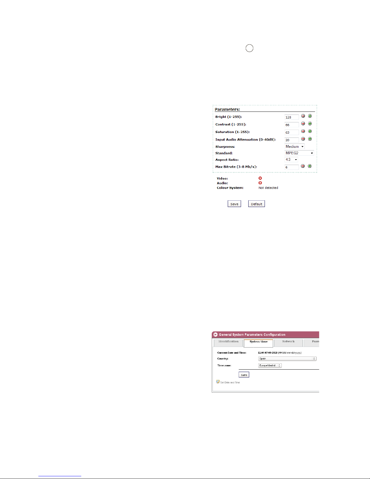
3) To modify the date and time of the unit, click on the option CONFIGURE DATE AND
TIME in the lower part of the screen.
4) Once nished conguring the data you can save it by clicking on SAVE in the lower
part of the screen.
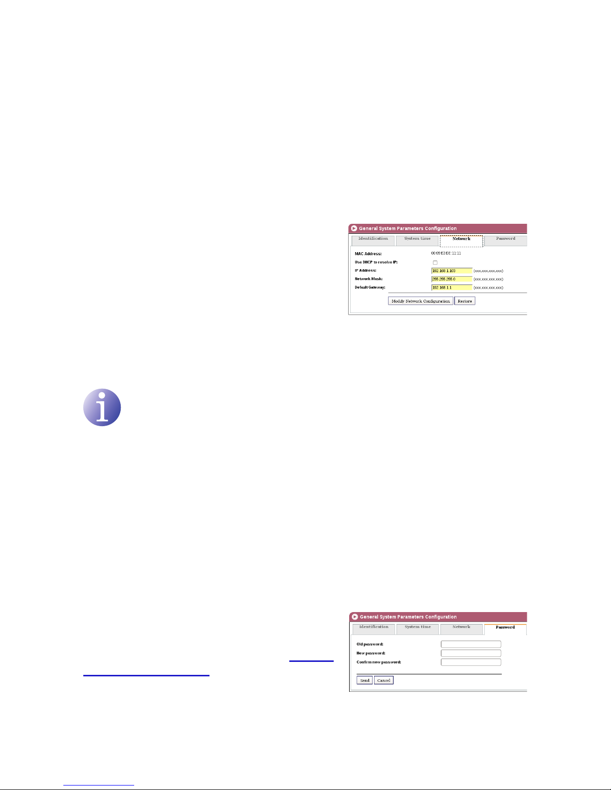
Network
1) Select the GENERAL menu and then the CONFIGURATION submenu.
2) Select the NETWORK tab.
The NETWORK conguration tab establishes the
parameters for connecting the MAC 201 unit to the
Ethernet network.
JMAC ADDRESS: the unit automatically shows
its MAC address for connection to the network.
JUSE DHCP TO RESOLVE IP: select this option
for the unit to obtain an IP address automatically
using the DHCP protocol. If you select this op-
tion it will not be necessary for you to congure
the following elds.
NOTE
If the administrator of the local area network assigns static IP network addresses,
never activate this option. Only activate this option if there is a local area network
switching unit capable of assigning dynamic IP addresses by DHCP protocol.
JIP ADDRESS: enter a static IP address within the valid range for the local area network
to which the unit is connected.
JNETWORK MASK: enter the local area network mask.
JDEFAULT GATEWAY: enter the IP address of the default gateway in the local network
to which the unit is connected.
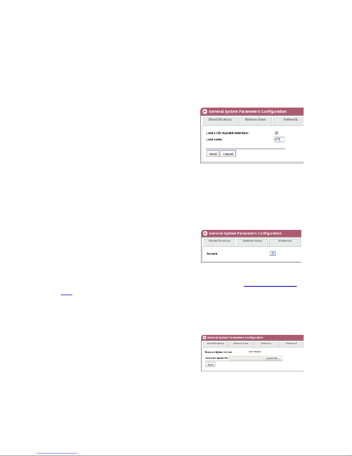
Password
1) Select the GENERAL menu and then the CONFIGURATION submenu.
2) Select the PASSWORD tab.
The PASSWORD conguration tab enables you to
change the current password for access to the web
interface of the MAC 201unit (see section Connec-
tion to the web interface).
JOLD PASSWORD: enter the current password.
JNEW PASSWORD: enter the new password.
EN