IKUSI 3854 User manual

MHD-201
REF. 3854
High-definition modulator
Web interface user guide

2

3
Index
4 Introduction
4 About this Manual
4 Product Description
5 Web interface connection
5 Ethernet configuration by application IKUSI HEADEND DISCOVERY
6 Ethernet manually configuration
7 General Configuration
7 Main Menu
8 Identification
8 Local configuration
9 Network configuration
10 Web access password
11 Save/Restore configuration
12 Upgrade
12 Restart
14 Signals Adjustment
14 Services
14 Input settings
15 Output settings
16 DVB-T Output
17 Network settings
18 IP Output
18 USB player
19 Status
19 Input
19 Output
20 General
21 Reports
22 Settings
23 Logs
ES

Introduction
4
Introduction
About this Manual
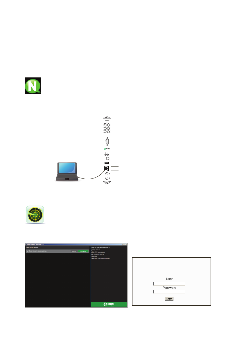
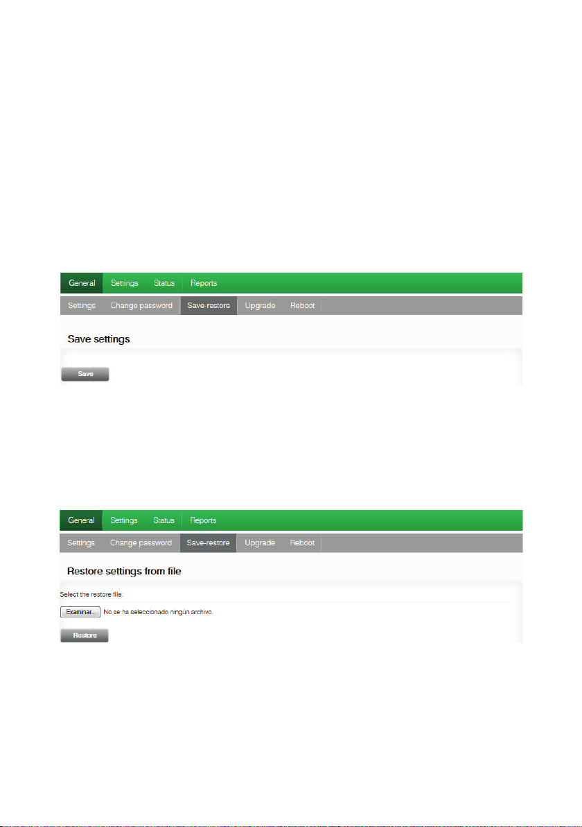
This manual describes the conguration environment of the MHD-201 modulator based on
web interface via Ethernet connection.
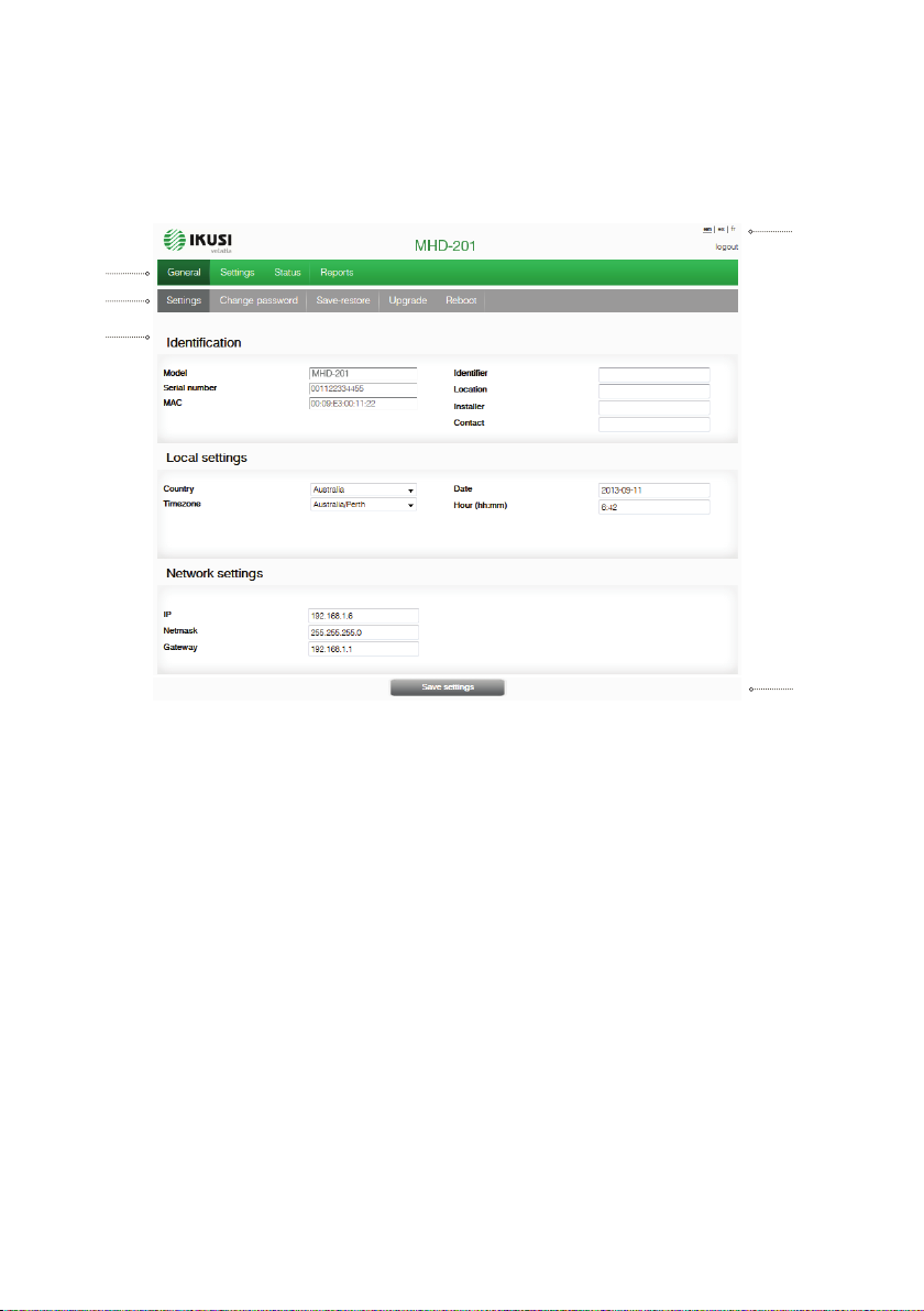
The Manual covers all conguration options: from start-up and operation, to adjusting the
settings and troubleshooting for the MHD-201.
The description consist of the connection procedure and access to the conguration set-
tings, description of the environment and its contents, conguration options and interpreta-
tion of the information on the screen.
NOTE
This conguration manual is a practical reference guide. For the correct use and
installation of the MHD-201, it is essential to read the corresponding user manual
(please see www.ikusi.tv for the manual).
Product Description
The MHD-201 is a standalone modulator that can process different Video and Audio for-
mats, to create a high-denition COFDM channel.
This product offers a solution to video signal distribution requirements in residential installa-
tions, hotels, special buildings or security video monitoring installations with COFDM digital
TV modulation. Likewise, the MHD-201 comes with a web Interface which can incorporate
new functions thanks to the equipment’s evolvable software, such as: video playback from
USB for digital signage and other possible future functions
Features
The unit has various inputs:
• Two analogue audio and video channels, through 6 RCA connectors.
• One digital video and audio channel in HDMI format, through an HDMI connector.
• One digital video and audio channel in HD-SDI format, through a BNC connector.
Output: Digital DVB-T TV signal over an RF carrier in VHF/UHF and IP signal.
Conguration:
• Web interface via Ethernet Connection
Possible input combinations:
•SD CVBS/Audio + SD CVBS/Audio
•SD HDMI + SD CVBS/Audio
•SD SDI + SD CVBS/Audio
•SD + USB
•HD HDMI
•HD SDI
•HD + USB
2 simultaneous SD channels
1 channel SD + USB
1 channel HD
1 channel HD + USB

Web Interface Connection
5
Web Interface Connection
Ethernet Connection
The web user interface can be used to congure all the MHD-201 unit’s settings, using an
Ethernet connection and a web browser.
NOTE
To view the graphics provided in the unit’s conguration programme correctly,
we recommend installing Mozilla Firefox 1.5 or later (www.mozilla.com) on the
controlling PC.
Use a PC with an Ethernet network card and a CAT-5E Ethernet cable.
Ethernet configuration by application:
I
k
u
s
i
H
e
a
d
e
n
d
D
i
s
c
o
v
e
r
y
Download the IKUSI HEADEND DISCOVERY application available on the
website (http://customerarea.ikusi.tv). In the window we will nd the model, the
MAC number, serial number and manufacturing rmware version to access the
interface of this module simply click on the SET button. In the home page the
USERNAME AND PASSWORD elds appear, enter “admin” in both, click on the ENTER
button.
MHD-201
2
13
DVB-T OUT
HDMI
SDI
USB
LAN
V/A 1
SYNC STATUS
+12V
Link
Act
V/A 2
VIDEO
AUDIO
L
AUDIO
R
CONTROL
VIDEO
AUDIO
L
AUDIO
R
Ref. 3854
MHD-201
DIGITALMODULATOR
KEY
1 - Ethernet Connector (LAN port, RJ-45)
2 - Link LED
3 - Activity LED
ES

Web Interface Connection
6
Ethernet manually configuration:
1) Access the PC’S TCP/IP Settings and congure the following parameters:
F* PC’S /IP Address: 192.168.1.1
F* Subnet Mask: 255.255.255.0
2) Connect the PC to the LAN port (RJ-45) of the MHD-201 unit (position 1 in the diagram
below).
NOTE
The MHD-201 Ethernet Connector (position 1 in the diagram above), has two
light indicators:
JThe link LED (position 2 in the diagram above), remains continuously lit
without blinking to indicate that the link is working correctly.
JThe activity LED (position 3 in the diagram above), blinks to indicate that the
link is active.
NOTE
The conguration process must be carried out in local mode, even though the
unit can be accessed from any PC on the LAN.
3) Start the web browser and enter the MHD-201 unit’s IP address:
FINITIAL IP ADDRESS: 192.168.1.6
NOTE
You may change this initial IP address later if you wish to.
NOTE
The unit is also assigned the default IP address 10.254.254.254
This IP address cannot be modied.
4) Click on ENTER to access the home page.
5) Enter the user name “admin” and the password “admin”.
NOTE
The unit connected to the PC will auto-
matically disconnect if 15 minutes pass
without any interaction.
.
MHD-201

General Configuration
7
General Configuration
Main menu
1-Main menu 2-Submenus 3-Work area 4-Language selection 5-Save configuration
To explore the different menus, select each option in the menus area (position 1 in the
diagram above). Depending on the options available in each menu, there will be one or
various submenus (position 2 in the diagram above). In turn, each submenu may have one
or more conguration tabs.
JTo change the interface’s language settings, click on the option corresponding to your
preferred language (position 4 in the diagram above): ES= Spanish; EN= English; FR=
French.
JTo save the settings you have changed, click on the SAVE CONFIGURATION option,
(position 5 in the diagram above).
2
3
1
4
5
ES

General Configuration
8
Identification
1) Select the GENERAL menu and then the CONFIGURATION submenu.
2) Access the IDENTIFICATION menu.
The IDENTIFICATION tab provides conguration data identifying the MHD-201 unit.
JMODEL: The name of the unit. This information cannot be modied.
JSERIAL NUMBER: Displays the manufacturers’ serial number identifying the unit.
This information cannot be modied.
JMAC ADDRESS: Automatically displays the MAC address of the unit for connection
to the network. This information cannot be modied.
JIDENTIFIER: Identifying name assigned to the unit by the installer or operator.
JLOCATION: Name of the location where the unit is installed (for example: a post code).
JINSTALLER: Name of the installer or operator.
JCONTACT:
Contact details of the installer or operator (for example: a telephone number).
3) Once you have nished conguring the data, you can save the changes by clicking on
the SAVE button on the lower part of the tab.
Local configuration
1) Select the GENERAL menu and then the CONFIGURATION submenu.
2) Access the LOCAL CONFIGURATION tab.
This section is used to set the date, time and standard time zone of the MHD-201 modula-
tor.
JCOUNTRY: Select the country in which the unit is operating.

General Configuration
9
JTIME ZONE: Set the time zone of the country in which the unit is operating.
JCURRENT DATE AND TIME: Shows the hour, date and format (Date: YYYY-MM-
DD; Time: HH:MM).
3) Once you have congured the data, you can save the changes by clicking on SAVE on
the bottom part of the tab.
Network configuration
1) Select the GENERAL menu and then the CONFIGURATION submenu.
2) Access the NETWORK CONFIGURATION tab.
JIP ADDRESS: Enter a static IP address within the range valid for the local network to
which the unit is connected.
JNETWORK MASK: Enter the local network mask.
JDEFAULT GATEWAY: Enter the default gateway IP address in the local network to
which the unit is connected.
Web access password
1) Select the GENERAL menu and then the CONFIGURATION submenu.
2) Access the PASSWORD tab.
The PASSWORD conguration tab allows you to change the current password for acces-
sing the web interface of the MHD-201 unit (see web interface connection section).
ES

General Configuration
10
JOLD PASSWORD: Enter the current password.
JNEW PASSWORD: Enter the new password.
JCONFIRM NEW PASSWORD: Re-enter the new password.
3) Once you have congured the data, you can save your changes by clicking on SAVE in
the lower part of the tab.
Save/Restore configuration
1) Select the GENERAL menu and then the SAVE/RESTORE menu.
All the conguration data established in the unit and accessible through the menus, sub-
menus and web interface tabs can be stored in a backup le.
Likewise, all the unit’s settings can be restored using a previously existing backup image.
2) Access the SAVE CONFIGURATION section and click on the SAVE button to save a
backup copy le. A window will open allowing you to select the location and lename
of the security copy.
3) Access the RESTORE CONFIGURATION FROM BACKUP section and click on the
SELECT BACKUP COPY button to load a backup copy. A window will open allowing
you to select the location and backup le name. Click on the RESTORE button.

General Configuration
11
4) Access the RESTORE FACTORY SETTINGS tab and click on the FACTORY RE-
SET button to reset the unit’s factory settings.
Updgrade
Select the GENERAL menu and then the UPDATE submenu. The unit will automatically
display the currently installed rmware version.
JSELECT THE UPDATE PACKAGE by clicking on the FILE SELECT button, to
select the rmware update le used by the unit.
JTo execute and load the new rmware click on the UPDATE button.
NOTE
The rmware update le has to be stored on the PC’s hard drive (it can be down-
loaded from http://customerarea.ikusi.tv).
ES

General Configuration
12
Resart
1) Select the GENERAL menu and then the RESTART submenu.
2) Click on the RESTART button.
The RESTART conguration le can now be used to restart the MHD-201 unit.
3) Once you have restarted the unit, the home page will appear again.
MHD-201

Settings
13
Settings
Services
Select the SETTINGS menu and then the SERVICES submenu. Specify the parameters
inside the SELECTION submenu:
JINPUT TYPE: Specify one of the ve possible combinations.
JOUTPUT TYPE: DVB-T and IP
Specify the parameters within the INPUT SETTINGS submenu:
JINPUT ASPECT RATIO: 16/9 or 4/3
The INPUT 1 tab reports on the status of the analogue AV TV input connected to the AV1
input, allowing you to modify how the audio and video components are processed.
To congure the AV2 input, select the INPUT 2 tab. The information, conguration options
and meanings are identical to those stated for INPUT 1.
ES

Settings
14
Within the OUTPUT SETTINGS submenu, specify the following parameters:
JBRIGHTNESS (1-255): Allows you to set the image’s brightness within a 1 to 255
range of values. You can enter a value or raise or lower the value unit-by-unit using the
buttons on the right of the value eld.
JCONTRAST (1-255): ): Allows you to set the image’s contrast within a 1 to 255 range of
values. You can enter a value or raise or lower the value unit-by-unit using the buttons
on the right of the value eld.
JSATURATION (1-255): Allows you to set the image’s saturation within a 1 to 255
range of values. You can enter a value or raise or lower the value unit-by-unit using the
buttons on the right of the value eld.
JINTENSITY: Allows you to set the video image’s sharpness, by selecting one of va-
rious preset values.
JCODIFICATION: Allows you to select the encoding standard for the digital audio and
video signal, from among the following options: MPEG2, MPEG4 and DEFAULT (if the
input signal is SD, the default encoding standard will be MPEG2; if the input signal is
HD, the encoding standard will be H.264 (1080p resolution only permits MPEG4).
JVIDEO BITRATE (4-15 Mbits/s): ): The unit can be congured for an input data
encoding rate of between 4 and 15 Mbits/s for SD quality and 4 and 19 Mbits/s for HD
quality . When selecting the encoding bitrate, the COFDM output bitrate must be taken
into account, as it must be sufcient to support the encoding bitrate. Otherwise, an
overow error warning will appear.
JAUDIO BITRATE: The unit can be congured for an input data encoding rate of 96;
128; 160; 192; 224; 256; 320 or 384 Kbits/s.
JAUDIO FORMAT: Allows you to select the three types of audio coding:
MPEG2 L1/L2, LC-AAC ó HE-AAC

Settings
15
JLOW LATENCY: It reduces the codication time for those applications where the
reaction time is important (i.e. cameras). The selection of the mode low latency, has a
signicant decrease in terms of codication efciency and images (with much move-
ment) quality.
JPIDs BLOCKING: To block any of the PIDs of each service, click to tick the correspon-
ding selection box.
JNAME: Tells you the name of each service
JSID: Allows you to modify the SID value (can be modied).
NOTE
The SID value is important for detecting the channels in some receivers.
All SID values should be different for the set of services processed by one or more
units that contribute to a shared RF output.
JLCN: Tells you the logical channel number.
JNAME CHANNEL (EIT): Allows you to name an event (ex. “pool camera”)
JEVENT DESCRIPTION (EIT): Allows you to add an explanation of an event
(ex. “open from 9am to 18pm).
To save the selected conguration, click on the SAVE SETTINGS button in the lower part
of the tab.
AV1 input signal status information:
JVIDEO: Tells you whether or not a valid video signal is being received at the AV1 input.
JAUDIO:
Tells you whether or not a valid audio signal is being received at the AV1 input.
JTV SYSTEM: States the colour system of the signal received at the AV1 input, which
may be: 480i ; 576i ; 480p ; 576p ; 720p 50Hz ; 720p 60Hz ; 1080i 50Hz ; 1080i 60Hz ;
1080p 25Hz ; 1080p 50Hz ; 1080p 60Hz ; 1080p 25Hz.
ES

Settings
16
DVB-T Output
Select the SETTINGS menu and then the DVB-T OUTPUT submenu.
Specify the following parameters in the DVB-T submenu:
JCHANNEL: Allows you to select and modify the output channel.
JFREQUENCY: States the output frequency of the current radiofrequency carrier and
allows you to modify its value. The frequency value must fall within the range valid for
bands VHF or UHF.
JATENUATION: Allows you to set the attenuation for the radiofrequency carrier signal
at the output, within a range of 0 dB to 25 dB.
JOFDM MODE:
Allows you to set the OFDM mode selecting between the values of 2K and 8K.
JBANDWIDITH: Allows you to set the bandwidth, selecting between the values of 6, 7
or 8 MHz.
JGUARD INTERVAL: Allows you to set the guard interval, by selecting between the
values 1/4, 1/8, 1/16 or 1/32, as fractions of a symbol period.
JCONSTELLATION: Allows you to set the output modulation constellation, by selecting
the 16QAM or 64QAM options.
JCODE RATE: Allows you to set the redundant encoding rate, by selecting from the
values 1/2, 2/3, 3/4, 5/6 or 7/8.
Select the ADJUSTMENTS menu and then the DVB-T submenu. Specify the following
parameters within the NETWORK SETTINGS submenu:

Settings
17
JNETWORK NAME: Allows you to assign a name to the network.
JPROVIDER: Allows you to specify the name of the service provider.
JNID: Allows you to assign a value to the network identier.
JTSID: Allows you to assign a value to the transport stream (or TS) identier.
NOTE
When conguring a headend with 2 or more units, the TSID value must be diffe-
rent in each unit.
JONID: Allows you to assign a value to the original network identier.
JNIT LCN MODE: Allows you to select the NIT LCN mode.
FOFF: No LCN descriptor will be entered in the NIT.
FEUROPE MODE: Enters the descriptor for Europe.
FINDEPENDENT TELEVISION COMMISSION: Enters the descriptor for the UK.
FNORDIG MODE V1: Enters the descriptor as per the Nordig V1 specication.
FNORDIG MODE V2: Enters the descriptor as per the Nordig V2 specication.
FGENERIC MODE: Generic LCN Descriptor.
JINSERT TDT-TOT: Allows you to choose whether or not to insert the date and time
information.
To save the selected conguration, click on the SAVE CONFIGURATION button on the
lower part of the tab.
JOUTPUT STATUS: Tells you the status of the output services.
JSERVICES NUMBER: Tells you the services number.
JMIN NULL: Tells you the minimum percentage of binary data at output.
JCURRENT NULL: Tells you the current percentage of binary data at output.
JOUTPUT BITRATE: Tells you the speed of the binary data at the unit’s output.
ES

USB player
18
IP Output
1) Select the SETTINGS menu and then the IP OUTPUT submenu.
Specify the following parameters in the IP submenu:
JPROTOCOL: The drop down menu offers two options : UDP and UDP/RTP. UDP is a
transport protocol.
JTime ToLive: Is a parameter used to restrict the multicasting range.
JQoS: Quality of Service.
JSOURCE IP: It shows the IP that is marked as issuer.
JSOURCE PORT: Identifying number of the port that is marked as issuer.
JACTIVATE VLAN: Allows you to Enable/Disable virtual LAN
JVLAN ID (0-4095): Identifying number of the virtual network.
JIP OUTPUT FORMAT: Selects between formats bit rate variable VBR or CBR cons-
tant.
JENABLE SAP: Check the box if you wish to transmit the program guide.
JIP: This data cannot be changed. It is the IP address assigned to the streamer module
on the Network tab in the Conguration window.
JUSER: The name entered will be transmitted on the SAP/SDP channel.
JSECONDA: Introduce the time interval, in seconds, at which the transmitted program-
mes guide will refresh.

Status
19
JSTATUS: Tells you the status of the output services
JNUMBER OF SERVICES: Reports the number of services.
JOUTPUT BITRATE: Tells you the speed of the binary data at the unit’s output.
USB Player
Select the SETTINGS menu and then the USB PLAYER submenu. Within the FILE PLA-
YBACK submenu, the Status section provides the following information:
JUSB INSERTED:
Tells you whether or not there is a pen drive connected to the unit.
JFILE AVAILABLE: Tells you the whether a le is available and can be played back
JPLAYER STATUS: Tells you whether the le is being played back or not.
Within the FILE PLAYBACK submenus, the Actions section allows you to choose whether
to play or stop playing the le, using two available buttons.
NOTE
The modulator generates a signal for 2 services even though we have one input
selected. This allows the TV to memorize the 2nd service which is destined to a
future employment of the USB ash drive.
With this we would avoid TV rescanning if the rst installation was made without
using the USB ash drive.
NOTE
In case of connecting only the USB ash drive, the input mode must be “2xCVBS”.
ES

Status
20
Status
1) Select the STATUS menu.
The STATUS tabs provide all the information on the statuses of the inputs and outputs, and
the other general parameters of the unit (alarms, temperature, services, etc).
2) Access the INPUT tab.
JINPUT 1 AND INPUT 2:
FVIDEO: shows whether there is a valid video signal at the input.
FAUDIO: shows whether there is a valid audio signal at the input.
FTV SYSTEM: shows the colour system at the input.
3) Access the OUTPUT tab.
JOUTPUT BITRATE:
FMAX BITRATE: Displays the maximum binary data rate supported by the unit.
FCURRENT NULL: Displays the current binary data percentage at the output not
containing any information.
FMIN NULL: Displays the minimum binary data percentage at the output not con-
taining any information.
This manual suits for next models
1
Table of contents
Other IKUSI Modulator manuals

IKUSI
IKUSI MAW-300 User manual

IKUSI
IKUSI HTL-STC User manual

IKUSI
IKUSI MAW-200 User manual

IKUSI
IKUSI MCP-400 User manual

IKUSI
IKUSI MHD-202 User manual

IKUSI
IKUSI MHD-201 Operating instructions

IKUSI
IKUSI MAW-201 User manual

IKUSI
IKUSI MCP-800 User manual

IKUSI
IKUSI MAC-HOME HD User manual

IKUSI
IKUSI MAW-201 User manual