IKUSI MAW-201 User manual

4
GENERAL DESCRIPTION
• The MAW-201 modulator generates double sideband, mono sound TV channels of the
systems B/G/D/K/I/L/M/N/Australia.
• Appropriate use with TV satellite receivers, VCR’s and video cameras.
• Possible connection of stereo sound sources. L and R signals are
summed by the modulator itself.
• Panel potentiometers for audio modulation and RF output level settings.
• Indoor mounting.
110
12
11 2 3 4
6
57
8
9
MAW-201 (3031)
MULTISTANDARD VHF/UHF TV MODULATOR
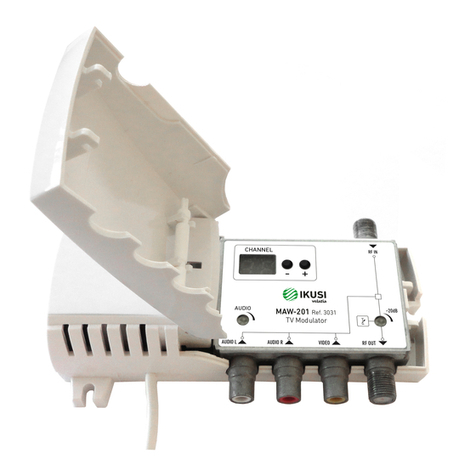
1. AUDIO L - audio left channel signal input connector (RCA type)
2. AUDIO R - audio right channel signal input connector (RCA type)
3. VIDEO - video signal input connector (RCA type)
4. RF OUT - RF signal output connector (F type)
5. RF IN - RF signal input connector (F type)
6. RF OUT - RF output signal level regulator
7. Two-digit LED display
8. Supply voltage indicator
9. Accessory to act on potentiometers
10. Power cord
11. AUDIO - sound subcarrier deviation regulator
12. Exterior lid (open by hand)
EN

5
MODEL MAW-201
REF. 3031
Video input Frequency range
Level / Impedance
20 Hz - 6 MHz
1 ±0.1 V / 75 Ω
Audio input
Frequency range
Level adjustment
Level / Impedance / Deviation *
20 HZ - 15 Hz
0 ... 7 dB
2x 775 mV RMS / 10 kΩ / 50 kHz*
RF output
Level (typical) / impedance
Level adjustment
Frequency range (programmable)
85 dBµV / 75 Ω
0 ... -20 dB
45 - 84 MHz ; 170 - 300 MHz ; 470 - 862 MHz
Selectable TV system B/G/D/K/H/I/L/M/N/AUSTRALIA
Number of outputs (1F) RF + (3 RCA) video/audio R-L
Number of inputs (1F) RF
Sound subcarrier frequency (programmable) 4.5 MHz ; 5.5 MHz ; 6.0 MHz ; 6.5 MHz
Fine tuning range of video carrier frequency (programm.) ± 2.25 MHz max. by 0.25 MHz step
Combining through loss 2.5 dB
Frequency range of RF combining 45 - 2150 MHz (TV+IF)
Video frequency response ± 1 dB
A/V ratio (programmable) 12/16 dB
Amplitude modulation depth, typical 81 %
Signal/noise ratio, weighted ≥ 55 dB
Supply voltage limit values, power consumption 198-250 V~ 50/60 Hz 3 W
Operating temperature range -10 ºC ... +50 ºC
Dimensions/Weight (packed) 133 x 73 x 39 mm / 0.36 kg
* Available to set standard deviation ± 50 kHz of sound carrier when input level 340 mV÷775 mV in both audio inputs.
MAIN FEATURES
RF OUT
RF IN
AUDIO L AUDIO R VIDEO
MAW-201
3031
TV

INSTALLATION INSTRUCTIONS
- Read the safety instruction first.
- To change the modulator settings, open the plastic cover.
- If RF IN connector on the modulator is not used, connect the 75 Ω load supplied.
- When modulators are cascading, space between channels must be no less than two (for example 21, 24, 27 and etc.).
-
Fix the box on the wall using two screws through the internal holes.
DEFAULT SETTINGS
1. Output channel E02;
2. Audio subcarrier deviation ±50 kHz (when audio signal level 1 kHz is 775 mV);
3. B/G standard; audio subcarrier 5.5 MHz (
Display
b5);
4. Test pattern generator OFF (
Display
no);
5. Frequency shift none (
Display
0);
6. P/S ratio -16 dB (
Display
16);
7. Output signal on (
Display
on);.
OPERATING
The modulator has two modes of operating:
1. NORMAL: sets after plug in;
Output channel can be selected in normal mode by pressing buttons “-“ or “+” (see tables).
2. SETTING: to enter the setting mode press and hold “-“ and “+” buttons simultaneously for 1 second, to exit
setting mode press and hold “-“ and “+” buttons simultaneously for 1 second.
Select of necessary to change parameter by pressing button “-“ and set necessary mode by pressing “+” button.
1. TV system setting:
a) after switching settings mode, indicator displays current TV system (see table);
b) set necessary TV system by pressing “-“ button (see tables);
c) after TV system changing, modulator sets to first channel of selected TV system (see tables), other settings
remains unchanged.
2. test pattern generator:
a) press “-“ button;
b) switching between OFF and ON by pressing button “+”, “no” - test pattern generator OFF, “t5” - test pattern
generator ON.
3. fine tuning of video carrier frequency:
a) press button “-“;
b) shift video carrier frequency by pressing button “+” (see table).
4. picture/sound ratio switching:
a) press button “-“;
b) switching between 12 dB and 16 dB by pressing button “+”.
5. output signal switching:
a) press button “-“;
b) switching between RF ON and RF OFF by pressing button “+”, “on” - RF ON, “oF” - RF OFF.
PROTECTION FROM UNAUTHORIZED ACCESS
To prevent unauthorized access press buttons “-” and “+” simultaneously twice in 0.5 sec. “LO” will briefly be
displayed. To revert to normal operation, repeat above procedure. “UL” will briefly be displayed. The symbol “LO”
appears, if you try to change settings in locked mode.
SOUND SUBCARRIER DEVIATION SETTING
When input signal level is from 340 mV to 775 mV in both audio inputs, use a regulator to set the sound
subcarrier deviation ±50 kHz. The factory set sound subcarrier deviation is ±50 kHz for an input signal level of
775 mV in both audio inputs.
OUTPUT SIGNAL LEVEL ADJUSTMENT
Use a regulator (figure 1, position 6) to adjust an output level. Output level adjustment range is 0 ÷ -20 dB.

10
TV system setting
Table 1
TV system Displayed Audio subcarrier Video standard
B/G b5 5.5 MHz PAL
D/K d6 6.5 MHz PAL, SECAM
Australia A5 5.5 MHz PAL
I i6 6.0 MHz PAL
L L6 6.5 MHz SECAM
M J4 4.5 MHz NTSC
N U4 4.5 MHz NTSC
Table 2
SYSTEM: B, G
Band Channel Displayed Vision C. Audio C.
BI E1 01 45,25 50,75
E2 02 48,25 53,75
E3 03 55,25 60,75
E4 04 62,25 67,75
BIII E5 05 175,25 180,75
E6 06 182,25 187,75
E7 07 189,25 194,75
E8 08 196,25 201,75
E9 09 203,25 208,75
E10 10 210,25 215,75
E11 11 217,25 222,75
E12 12 224,25 229,75
S2 S11 71 231.25 236.75
S12 72 238.25 243.75
S13 73 245.25 250.75
S14 74 252.25 257.75
S15 75 259.25 264.75
S16 76 266.25 271.75
S17 77 273.25 278.75
S18 78 280.25 285.75
S19 79 287.25 292.75
S20 80 294.25 299.75
Table 3
SYSTEM: D, K
Band Channel Displayed Vision C. Audio C.
BI/II C1 01 49,75 56,25
C2 02 59,25 65,75
C3 03 77,25 83,75
BIII C6 06 175,25 181,75
C7 07 183,25 189,75
C8 08 191,25 197,75
C9 09 199,25 205,75
C10 10 207,25 213,75
C11 11 215,25 221,75
C12 12 223,25 229,75
SR2/
SR3
SR11 71 231.25 237.75
SR12 72 239.25 245.75
SR13 73 247.25 253.75
SR14 74 255.25 261.75
SR15 75 263.25 269.75
SR16 76 271.25 277.75
SR17 77 279.25 285.75
SR18 78 287.25 293.75
S19 79 295.25 301.755
Table 4
SYSTEM: I/South Africa
Band Channel Displayed Vision C. Audio C.
III 4 04 175.25 181.25
5 05 183.25 189.25
6 06 191.25 197.25
7 07 199.25 205.25
8 08 207.25 213.25
9 09 215.25 221.25
10 10 223.25 229.25
11 11 231.25 237.25
12 12 239.25 245.25
13 13 247.25 253.25
CANALES VHF BANDA I, III / VHF BAND I, III CHANNELS / CANAUX VHF BANDE I, III

11
Table 5
SYSTEM: B, Australia
Band Channel Displayed Vision C. Audio C.
BI D1 01 57,25 62,75
D2 02 64,25 69,75
BIII D6 06 175,25 180,75
D7 07 182,25 187,75
D8 08 189,25 194,75
D9 09 196,25 201,75
D10 10 210,25 215,75
D11 11 217,25 222,75
D12 12 224,25 229,75
Hiper
band
S12 82 238.25 243.75
S13 83 245.25 250.75
S14 84 252.25 257.75
S15 85 259.25 264.75
S16 86 266.25 271.75
S17 87 273.25 278.75
S18 88 280.25 285.75
S19 89 287.25 292.75
S20 90 294.25 299.75
Table 6
SYSTEM: L, France
Band Channel Displayed Vision C. Audio C.
BIII L05 05 176,00 182,50
L06 06 184,00 190,50
L07 07 192,00 198,50
L08 08 200,00 206,50
L09 09 208,00 214,50
L10 10 216,00 222,50
Inter
ban-
de
L 71 236.75 243.25
M 72 248.75 255.25
N 73 260.75 267.25
O 74 272.75 279.25
P 75 284.75 291.25
Q 76 296.75 303.25
Table 7
SYSTEM: M, Japan
Band Channel Displayed Vision C. Audio C.
III 5 05 177.25 181.75
6 06 183.25 187.75
7 07 189.25 193.75
8 08 193.25 197.75
9 09 199.25 203.75
10 10 205.25 209.75
11 11 211.25 215.75
Table 8
SYSTEM: N, USA
Band Channel Displayed Vision C. Audio C.
Low 2 02 55,25 59,75
3 03 61,25 65,75
4 04 67,25 71,75
5 05 77,25 81,75
High A7 07 175,25 179,75
A8 08 181,25 185,75
A9 09 187,25 191,75
A10 10 193,25 197,75
A11 11 199,25 203,75
A12 12 205,25 209,75
A13 13 211,25 215,75

12
Table 9
SYSTEM: B, Australia
Band Channel Displayed Vision C. Audio C.
IV 20 20 471.25 476.75
21 21 478.25 483.75
22 22 485.25 490.75
23 23 492.25 497.75
24 24 499.25 504.75
25 25 506.25 511.75
26 26 513.25 518.75
27 27 520.25 525.75
28 28 527.25 532.75
29 29 534.25 539.75
30 30 541.25 546.75
31 31 548.25 553.75
32 32 555.25 560.75
33 33 562.25 567.75
34 34 569.25 574.75
35 35 576.25 581.75
V 36 36 583.25 588.75
37 37 590.25 595.75
38 38 597.25 602.75
39 39 604.25 609.75
40 40 611.25 616.75
41 41 618.25 623.75
42 42 625.25 630.75
43 43 632.25 637.75
44 44 639.25 644.75
45 45 646.25 651.75
46 46 653.25 658.75
47 47 660.25 665.75
48 48 667.25 672.75
49 49 674.25 679.75
50 50 681.25 686.75
51 51 688.25 693.75
52 52 695.25 700.75
53 53 702.25 707.75
54 54 709.25 714.75
55 55 716.25 721.75
56 56 723.25 728.75
57 57 730.25 735.75
58 58 737.25 742.75
59 59 744.25 749.75
60 60 751.25 756.75
61 61 758.25 763.75
62 62 765.25 770.75
63 63 772.25 777.75
64 64 779.25 784.75
65 65 786.25 791.75
66 66 793.25 798.75
67 67 800.25 805.75
68 68 807.25 812.75
69 69 814.25 819.75
70 70 821.25 826.75
71 71 828.25 833.75
72 72 835.25 840.75
73 73 842.25 847.75
74 74 849.25 854.75
75 75 856.25 861.75
Table 10
SYSTEMS: M, N
Channel Vision C. Audio C. Channel Vision C. Audio C.
J4 U4 J4 U4
13 14 471.25 475.75 46 47 669.25 673.75
14 15 477.25 481.75 47 48 675.25 679.75
15 16 483.25 487.75 48 49 681.25 685.75
16 17 489.25 493.75 49 50 687.25 691.75
17 18 495.25 499.75 50 51 693.25 697.75
18 19 501.25 505.75 51 52 699.25 703.75
19 20 507.25 511.75 52 53 705.25 709.75
20 21 513.25 517.75 53 54 711.25 715.75
21 22 519.25 523.75 54 55 717.25 721.75
22 23 525.25 529.75 55 56 723.25 727.75
23 24 531.25 535.75 56 57 729.25 733.75
24 25 537.25 541.75 57 58 735.25 739.75
25 26 543.25 547.75 58 59 741.25 745.75
26 27 549.25 553.75 59 60 747.25 751.75
27 28 555.25 559.75 60 61 753.25 757.75
28 29 561.25 565.75 61 62 759.25 763.75
29 30 567.25 571.75 62 63 765.25 769.75
30 31 573.25 577.75 64 771.25 775.75
31 32 579.25 583.75 65 777.25 781.75
32 33 585.25 589.75 66 783.25 787.75
33 34 591.25 595.75 67 789.25 793.75
34 35 597.25 601.75 68 795.25 799.75
35 36 603.25 607.75 69 801.25 805.75
36 37 609.25 613.75 70 807.25 811.75
37 38 615.25 619.75 71 813.25 817.75
38 39 621.25 625.75 72 819.25 823.75
39 40 627.25 631.75 73 825.25 829.75
40 41 633.25 637.75 74 831.25 835.75
41 42 639.25 643.75 75 837.25 841.75
42 43 645.25 649.75 76 843.25 847.75
43 44 651.25 655.75 77 849.25 853.75
44 45 657.25 661.75 78 855.25 859.75
45 46 663.25 667.75
CANALES UHF BANDA IVY BANDA V / UHF BAND IV AND BAND V CHANNELS / CANAUX UHF BANDE IV ET BANDE V

13
Table 11
SYSTEMS: I, G, H, K, L
Band Channel Vision C. Audio C.
Stand.G,H
Audio C.
Stand.I
Audio C.
Stand.K,L
IV 21 471.25 476.75 477.25 477.75
22 479.25 484.75 485.25 485.75
23 487.25 492.75 493.25 493.75
24 495.25 500.75 501.25 501.75
25 503.25 508.75 509.25 509.75
26 511.25 516.75 517.25 517.75
27 519.25 524.75 525.25 525.75
28 527.25 532.75 533.25 533.75
29 535.25 540.75 541.25 541.75
30 543.25 548.75 549.25 549.75
31 551.25 556.75 557.25 557.75
32 559.25 564.75 565.25 565.75
33 567.25 572.75 573.25 573.75
34 575.25 580.75 581.25 581.75
35 583.25 588.75 589.25 589.75
36 591.25 596.75 597.25 597.75
37 599.25 604.75 605.25 605.75
V 38 607.25 612.75 613.25 613.75
39 615.25 620.75 621.25 621.75
40 623.25 628.75 629.25 629.75
41 631.25 636.75 637.25 637.75
42 639.25 644.75 645.25 645.75
43 647.25 652.75 653.25 653.75
44 655.25 660.75 661.25 661.75
45 663.25 668.75 669.25 669.75
46 671.25 676.75 677.25 677.75
47 679.25 684.75 685.25 685.75
48 687.25 692.75 693.25 693.75
49 695.25 700.75 701.25 701.75
50 703.25 708.75 709.25 709.75
51 711.25 716.75 717.25 717.75
52 719.25 724.75 725.25 725.75
53 727.25 732.75 733.25 733.75
54 735.25 740.75 741.25 741.75
55 743.25 748.75 749.25 749.75
56 751.25 756.75 757.25 757.75
57 759.25 764.75 765.25 765.75
58 767.25 772.75 773.25 773.75
59 775.25 780.75 781.25 781.75
60 783.25 788.75 789.25 789.75
61 791.25 796.75 797.25 797.75
62 799.25 804.75 805.25 805.75
63 807.25 812.75 813.25 813.75
64 815.25 820.75 821.25 821.75
65 823.25 828.75 829.25 829.75
66 831.25 836.75 837.25 837.75
67 839.25 844.75 845.25 845.75
68 847.25 852.75 853.25 853.75
69 855.25 860.75 861.25 861.75
Table 12
Displayed Shift, MHz
0 0
1 +0.25
2 +0.5
3 +0.75
4 +1.0
5 +1.25
6 +1.5
7 +1.75
8 +2.00
9 +2.25
-9 -2.25
-8 -2.00
-7 -1.75
-6 -1.5
-5 -1.25
-4 -1.0
-3 -0.75
-2 -0.5
-1 -0.25
Table 13
Displayed Audio level
mV/dB
0 775/0
3 615/+2
4 490/+4
6 388/+6
-6 1545/-6
-4 1227/-4
-2 975/-2
AJUSTE FINO / FINE TUNING / RÉGLAGE FINE
14
INSTRUCCIONES DE SEGURIDAD
SAFETY INSTRUCTIONS
INSTRUCTIONS DE SÉCURITÉ

15
San Sebastián, October 2019
Jesús Gómez Río
R&D Director
EC-Declaration of Conformity
We, Manufacturer
Ikusi Electrónica S.L.
Paseo Miramón, 170
20014 San Sebastián, Spain
declare that the product
marking
LVD
are in conformity with
Council Directive 2014/35/EU
Standards to which conformity is declared : ROHS
are in conformity with
RoHS 3. Directive 2015/863/EU
Standards to which conformity is declared :
EMC
are in conformity with
Council Directive 2014/30/EU
Standards to which conformity is declared :
Stand-alone analogic modulator
MAW-201 (4485)
EN 50083-2:2012+A1:2015
Cable networks for television signals, sound signals and interactive services. Part 2: Electromagnetic compatibility for
equipment.
EN 61000-3-2:2014
Electromagnetic compatibility (EMC) - Part 3-2: Limits - Limits for harmonic current emissions (equipment input current up to
and including 16 A per phase.
EN 61000-3-3:2013
Electromagnetic compatibility (EMC) - Part 3-3: Limits - Limitation of voltage changes, voltage fluctuations and flicker in public
low-voltage supply systems, for equipment with rated current up to 16 A per phase and not subject to conditional connection.
EN 62368-1:2014
Audio/video, information and communication technology equipment - Part 1: Safety requirements (LVD) (Endorsed by AENOR
in September of 2014).
UNE-EN 50581:2012
Technical documentation for the assessment of electrical and electronic products with respect to the restriction of hazardous
substances (RoHS) (Endorsed by AENOR in November of 2012)

120212A
Ikusi declara que este producto es conforme con la directiva 2014/53/UE
Ikusi declares that this product is in accordance with 2014/53/UE directive
Ikusi déclare que ce produit est conforme à la directive 2014/53/UE
Pº Miramón, 170 · 20014 San Sebastián · SPAIN
Tel.: +34 943 44 88 00 · Fax: +34 943 44 88 20
Other manuals for MAW-201
1
Table of contents
Other IKUSI Modulator manuals

IKUSI
IKUSI MCP-400 User manual

IKUSI
IKUSI MHD-201 Operating instructions

IKUSI
IKUSI MAW-201 User manual

IKUSI
IKUSI MAC 201 User manual

IKUSI
IKUSI MHD-201 User manual

IKUSI
IKUSI MAC-HD User manual

IKUSI
IKUSI MAW-200 User manual

IKUSI
IKUSI AV-COFDM User manual

IKUSI
IKUSI MHD-202 User manual

IKUSI
IKUSI HTL-STC User manual