IMER KOINE 4 Guide

PLASTERING MACHINE
Operating,maintenance,spare parts manual
3223425 R18 - 2018/09
KOINE 4/5

2
IMER INTERNATIONAL S.p.A.
INTONACATRICI IMER
Special attention must be given to warnings with this symbol:
FIG. 1
ENGLISH
( 1 ) WHEELED FRAME
( 2 ) HOPPER
( 3 ) MIXING CHAMBER
( 4 ) WATER CIRCUIT
( 4a ) WATER PUMP
( 4b ) MICROMETRIC VALVE
( 4c ) FLOW METER
( 4d ) WATER PRESSURE SWITCH
( 4e ) PRESSURE REDUCER
( 5 ) ELECTRICAL PANEL
( 5a ) COMPRESSOR PRESSURE
SWITCH
( 5b ) MACHINE PRESSURE SWITCH
( 6 ) DIAPHRAGM COMPRESSOR
( 6a ) RELIEF VALVE COMPRESSOR
( 7 ) CELL WHEEL
( 8 ) CELL WHEEL GEARMOTOR
( 8a ) MORTAR PUMP GEARMOTOR
( 9 ) MIXER
( 10 ) MORTAR PUMP
( 10a ) STATOR
( 10b ) CAM SCREW
( 11 ) MANIFOLD
( 12 ) MATERIAL DELIVERY HOSE
( 12a ) SPRAY JET
( 13 ) GRILLE WITH SACK SPLITTER
( 14 ) HOPPER WATER OUTLET PLUG

3
IMER INTERNATIONAL S.p.A.
KOINE 4/5
Dear Customer,
compliments on your purchase of this IMER plaster mixer, the re-
VXOWRIORQJVWDQGLQJH[SHULHQFHLQWKH¿HOGDQGIHDWXUHVPD[LPXP
UHOLDELOLW\DQGLQQRYDWLYHWHFKQLFDOVROXWLRQV
- WORKING IN SAFETY.
To ensure complete safety, read all the instructions in this
manual carefully.
This OPERATION AND MAINTENANCE manual must be kept
by the Site Manager and be always available for consultation.
The manual is considered part of the machine and must be stored
for future reference (EN ISO 12100) through to scrapping of the
machine itself. If the manual is lost or damaged, a replacement
copy can be ordered from the manufacturer.
The manual contains the EC declaration of conformity 2006/42/EC)
important information on construction site procedures, installation,
operation, maintenance and requests for spare parts. Neverthe-
less, the user must both have adequate experience and knowledge
of the machine prior to use: the user should be trained by a person
totally familiar with the operation and use of this machine.
In order to ensure operator safety, safe operation and long service
life, all instructions in this manual must be observed, together with
the requirements of current legislation governing work safety (use
of safety footwear and adequate clothing, use of helmets, gloves,
goggles etc.).
- Make sure that all signs are legible.
1HYHUPDNHDQ\PRGL¿FDWLRQVWRWKHPHWDOVWUXFWXUH
or plastering machine systems
IMER INTERNATIONAL accepts no responsibility in the event
of failure to comply with laws governing the use of this type of
equipment, with particular reference to: improper use, incorrect
SRZHUVXSSO\ODFNRIPDLQWHQDQFHXQDXWKRULVHGPRGL¿FDWLRQDQG
failure to comply, either wholly or partially, with the instructions set
out in this manual.
IMER INTERNATIONAL reserves the right to modify the cha-
racteristics of the plastering machine and/or contents of this
manual, without the obligation to update the previous machine
and/or manuals.
1. TECHNICAL DATA
7DEOH SURYLGHV WKH WHFKQLFDO VSHFL¿FDWLRQV RI WKH SODVWHULQJ
PDFKLQHZLWKUHIHUHQFHWR¿JXUH
2. DESIGN STANDARDS
The plastering machines have been designed and constructed
DFFRUGLQJWRWKHVWDQGDUGVVSHFL¿HGLQWDEOH
3. NOISE EMISSION LEVEL
Table 1 shows the sound pressure levels of the plastering machine
measured at the ear of the operator (LpA at 1m) and noise emission
levels in the environment (power LWA) measured according to EN
ISO 3744 (2000/14/CE).
4. DESCRIPTION OF PLASTERING MACHINE OPERATION
- The plastering machine is designed for use in building
sites, for mixing and pumping all mixed mortars declared as
compatible with this type of machine by the material manu-
facturers: gypsum based plasters, anhydrite based plasters,
lime/cement based plasters, reverse insulation plasters,
grouting mortar etc.
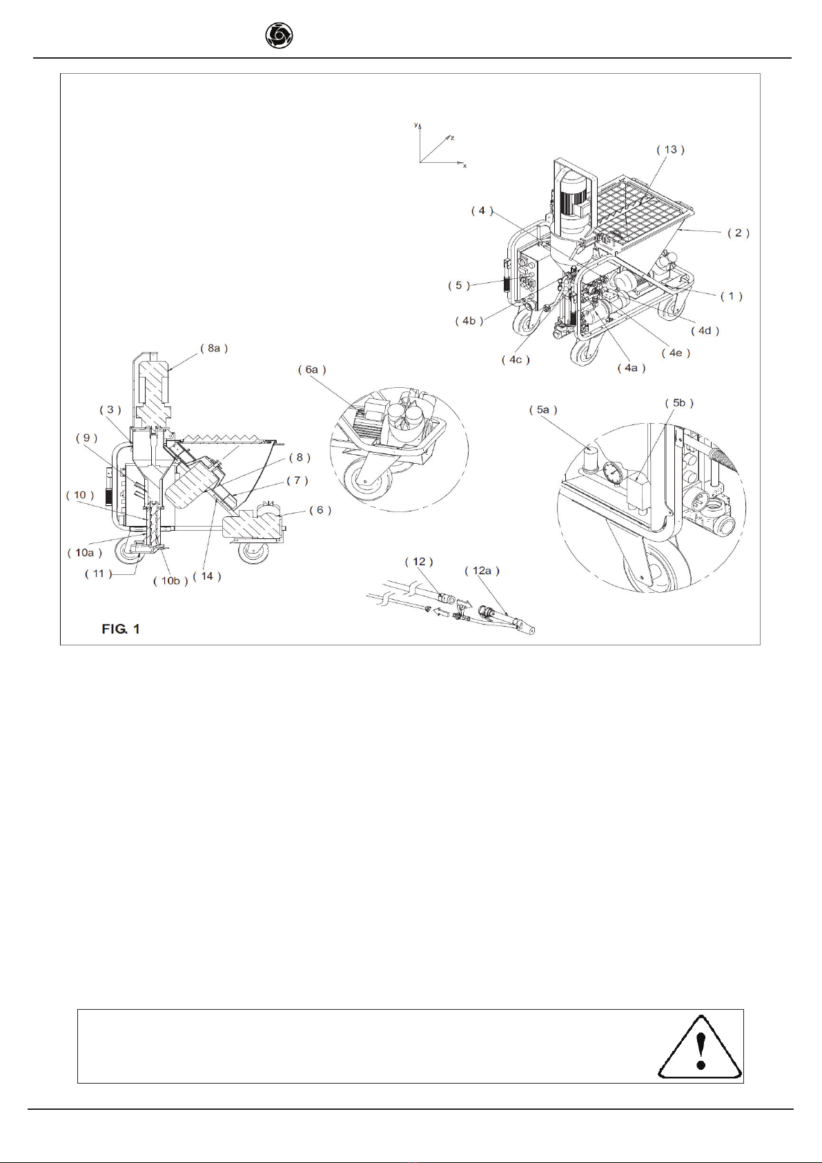
4.1 PLASTERING MACHINE DESCRIPTION (Fig. 1)
The plastering machine comprises a wheeled frame (ref.1), which
supports a hopper (ref.2), a mixing chamber (ref.3), a water circuit
(ref.4) complete with self-priming pump (ref.4a), an electrical panel
(ref.5), and a diaphragm compressor (ref.6).
The pre-mixed dry material is poured in to the hopper, in which
a cell-wheel-dispenser (ref.7), activated by a gearmotor (ref.8),
moves the material inside the mixing chamber. The mixing cham-
ber contains
a mixer (ref.9), activated by a gearmotor (ref.8a), which mixes the
material with water delivered to the chamber by the water pump.
7KHZDWHUÀRZUDWHLVUHJXODWHGE\PHDQVRIDPLFURPHWULFYDOYH
UHIEDQGGLVSOD\HGYLDDÀRZPHWHUUHIF7KHPL[HUGULYHV
a helical rotor pump (ref.10) which conveys the material via a
rubber hose (ref.12) to the spray jet (ref.12a). Ther air pumped
by the compressor is also delivered to the jet to enable spray
application onto the walls.
5. OPERATION SAFETY
- Before using the plastering machine, ensure that it is
¿WWHGZLWKDOOVDIHW\GHYLFHV
- Never insert parts of the body and/or tools in the hopper
or mixing chamber during operation.
All current standards governing accident prevention and safety
devices must be observed in the workplace.
Take care when handling sacks of material to avoid dispersion of
dust with inhalation of the latter; if this is not possible masks must
be worn to protect the mouth and nose.
- Never use the machine in areas subject to the risk of
H[SORVLRQ¿UHVRULQXQGHUJURXQGLQVWDOODWLRQV
The plastering machine is not equipped with a lighting system
DQGWKHUHIRUHWKHZRUNSODFHPXVWEH¿WWHGZLWKDGHTXDWHOLJKWLQJ
The power lines must be laid to prevent any possible damage.
Never place the plastering machine on electric power cables.
Ensure that the electrical connection is protected against the risk
of water penetration in connectors. Use exclusively connectors
and couplings equipped with water spray protection.
- Never use inadequate or provisional electric lines; if in doubt
consult specialist personnel for assistance.
- Repairs to the electrical circuit must be performed exclusively by
specialised personnel. Disconnect the machine from the power
supply before performing maintenance or repairs.
-Avoid contact of electric wires with movable and/or moving parts
of the machine to avoid injury from contact with live metal parts.
6. ELECTRICAL SAFETY
The G.I.5 plastering machine is constructed according to standard
EN 60204-1, with protection against water sprays and protection
against overload and power failure.
The plastering machine must be connected to the earthing circuit.
TRANSLATED INSTRUCTIONS

4
IMER INTERNATIONAL S.p.A.
KOINE 4/5
7. MECHANICAL SAFETY
The hazardous points on the IMER plastering machine are
protected by means of suitable safety devices, which must remain
¿WWHGDWDOOWLPHVDQGNHSWLQSHUIHFWFRQGLWLRQVXFKDVWKHHOHFWULF
motor cooling fan guard and the grille on the hopper to prevent
contact with the cell wheel.
Also opening of the mixing chamber, either via the motor support
ÀDQJHRUWKHFRPSOHWHPL[LQJFKDPEHUVKXWVGRZQWKHURWDU\SDUWV
RIWKHPDFKLQHWKDQNVWRDVSHFL¿FVDIHW\PLFURVZLWFK
8. TRANSPORT
- Caution! Before moving the plastering machine, always
detach the power plug.
Before moving the plastering machine the water delivery hose and
material delivery line must be removed.
Only a minimal amount of the material should be in the hopper
when handling.
Release the wheel by means of the brake and move the mixer by
PHDQVRIWKHKDQGOHV¿J
FIG.2
- Caution! Before lifting the plastering machine, always
disassemble the compressor for separate transport.
- Caution! Before lifting the machine, always check that
DOOPDFKLQHFRPSRQHQWVDUHFRUUHFWO\VHFXUHGDQG¿WWHGLQ
place.
7ROLIWWKHPDFKLQHXVHWKHVSHFL¿FDWWDFKPHQWULQJV¿J
FIG.3
- Caution! Lift with care to avoid hazardous oscillations
&DXWLRQ1HYHUXVHSRLQWVRWKHUWKDQDVVSHFL¿HGLQ
¿JXUHWROLIWWKHPDFKLQHDQGLQSDUWLFXODUGRQRWKRRNXS
lifting equipment to the gearmotor guard.
Use lifting equipment suited to the overall weight of the machine
indicated in table 1.
To facilitate transport, the machine can be disassembled as
VKRZQLQ¿J
.
FIG.4
7KHZHLJKWRIWKHVXEXQLWVVKRZQLQ¿JDUHVSHFL¿HGLQWDEOH
9. INSTALLATION
3RVLWLRQWKHSODVWHULQJPDFKLQHRQDÀDWVXUIDFHLQDQDUHDZKHUH
it does not constitute an obstruction either during use or cleaning
at the end of the work shift and where a minimum quantity of
pipelines is required.
Secure the machine in place by means of the wheel brake (ref.5
¿J
10. CONNECTIONS
10.1 ELECTRICAL CONNECTION
- Ensure that the power supply voltage, mains frequency
and electrical connection (socket, fuses, cable) correspond
WRVSHFL¿FDWLRQVLQWDEOH
7KH HOHFWULFDO SRZHU OLQH PXVW EH ¿WWHG ZLWK SURWHFWLRQ DJDLQVW
current overload (e.g. by means of fuses or a thermal magnetic
cut-out) and with current dispersion to earth (e.g. with a differential
circuit breaker). The electric cable wire size must take into account
the operating currents and length of the line to avoid excessive
voltage drops.
Avoid use of extension leads wound on drums. The power cable
must be suitable for frequent movements and with an abrasion
resistant sheath (e.g. type H07RN-F).
Before connecting the plastering machine to the electrical mains,
HQVXUHWKDWDOOVDIHW\GHYLFHVDUH¿WWHGDQGDUHLQSHUIHFWFRQGL-
tion, and check in particular that the hopper grille is secured in
place, that the extension in good condition and that the plugs and
sockets are not wet.
Connect the plastering machine socket on the electrical panel to
WKHPDLQV¿J
FIG.5

5
IMER INTERNATIONAL S.p.A.
KOINE 4/5
10.2 WATER CONNECTION
&RQQHFWWKHZDWHUKRVHWDEOHWRWKHZDWHUPDLQV¿J
7KHZDWHUPDLQVPXVWJXDUDQWHHDPLQLPXPÀRZUDWHRI
20l/min.
2WKHUZLVHDWDQNRIVXLWDEOHFDSDFLW\OPXVWEH¿WWHGZLWK
clean water, to be kept full at all times, and from which water can
be taken by means of the self-priming pump supplied with the
machine. In this case the hose must have a minimum diameter
RIDPD[LPXPOHQJWKRIPSUHIHUDEO\DIRRW¿OWHUDQGPXVW
not be subject to deformation during use.
&DXWLRQ7KH¿UVWWLPHWKHZDWHUSXPS
is connected to the tank, it must be activated by manually
¿OOLQJWKHLQWDNHOLQH
The same operation must be repeated each time the circuit is
drained, or after a prolonged period of disuse.
FIG.6
10.4 AIR CONNECTION
&RQQHFWWKHDLUKRVHWRWKHPDFKLQHSDQHODQGVSUD\MHW¿J
FIG.7
11. START-UP
&ORVHWKHDLUYDOYHUHIDVXSSO\LQJWKHVSUD\MHW¿J
Open the micrometric valve (ref.8) virtually fully.
Turn the main switch/inverter (ref.1a) to position 1 or 2: in the
correct position the blue “phase correct” lamp illuminates (ref.1g).
Check that the water pressure gauge (ref.11) indicates a minimum
pressure of 3.5 bar and that the green “no water pressure” lamp
(ref.1i) is off. Otherwise, activate the pump by means of the water
pump switch (ref.1f). Press the water supplement pushbutton
(ref.1d) for 3-4 seconds.
Start the pump by means of the start pushbutton (ref.1c):
the lamp on the start/stop pushbutton illuminates and the mortar
pump starts up for a few seconds.
Open the spray jet air valve: the machine starts up. Check that the
water pressure does not fall below 2.5 bar; otherwise activate the
ZDWHUSXPS8VHWKHPLFURPHWULFYDOYHWRUHJXODWHWKHZDWHUÀRZ
UDWHGLVSOD\HGRQWKHÀRZPHWHUUHIZLWKUHVSHFWWR
- 800l/min if using gypsum based materials (pump D 6-3).
- 500l/min if using cement based materials (pump D 6-3).
Start the cell wheel by means of the relative switch (ref.1e) and
then stop it.
Close the air valve.
Fill the hopper with dry materials.
Open the air valve of the jet.Activate and deactivate the cell wheel
3 or 4 times by means of the relative switch
(2 -3 seconds operation, 2-3 seconds stopped) and then switch
on permanently. Regulate the water to obtain the consistency as
recommended by the material manufacturer. Close the air valve to
the spray gun. Check the material hoses to ensure perfect condi-
WLRQWKDWFRXSOLQJVDUHLQWDFWDQGWKHUHODWLYHVHDOVDUH¿WWHGDQG
SRXUDSSUR[OLWUHVRIJURXWLQWKH¿UVWVHFWLRQDQGWKHQFRQQHFW
them to the delivery manifold (ref.10) and spray jet. Check that
the cam levers ( A ) of the couplings have been tightened correctly
and that the seal
%LV¿WWHGDVVKRZQLQ¿J
FIG.8
FIG8
FIG.9
Start the machine: when the correct consistency of material is
delivered from the jet normal operation can be started.
The machine starts and stops by opening and closing the air
supply to the spray jet.
7KHPDFKLQHLV¿WWHG ZLWK SURWHFWLRQDJDLQVWSRZHU IDLOXUH DQG
water pressure failure: if one of these occur, press the start pu-
shbutton to resume operation.
To stop the machine in the event of an emergency, press the red
emergency pushbutton (ref.1b) to shut down the machine - all
moving parts are shut down - and then turn the main switch to 0
and remove the electric power plug from the socket (ref.1l).

6
IMER INTERNATIONAL S.p.A.
KOINE 4/5
THERMAL CUTOUT PROTECTION:
- The electric motors are protected against overload by
thermal magnetic cutouts, the activation of which is displayed
by illumination of the red lamp (ref.1h). In this case, after the
PRWRUVKDYHFRROHGWKHVSHFL¿FSHUVRQQHOVKRXOGRSHQWKH
electrical panel and reset the cutouts.
For the mortar pump motor (ref.12) there is an additional
safety protection: a thermal sensor shuts down the machine
in the event of a motor temperature overload.
12. OPERATION
- The hopper safety grille must be ¿WWHG DQG VHFXUHG
at all times.
Never place materials other than premixed dry materials in
the hopper.
- Opening of the mixing chamber causes shutdown of the
PDFKLQHPRYLQJSDUWV¿J)LUVWFORVHWKHPL[LQJFKDPEHU
and press the start pushbutton to start the machine.
:HDUVSHFL¿HGSURWHFWLYHGHYLFHVEHIRUHZRUNLQJRQ
the machine
FIG.11
FIG.10
Regulate the water to obtain the required consistency.
'LIIHUHQWGLDPHWHUVRIGHÀHFWRUDUHDYDLODEOHPP
WKHVPDOOHUGHÀHFWRUVHQDEOHLPSURYHGQHEXOLVDWLRQDQGWKHODUJHU
ones are more suited to materials with a larger particle size.
)RUVWDQGDUGSODVWHULQJPDWHULDOVWKHGHÀHFWRUZLWKPPKROH
(ref.9b) is used.
However, it is important to measure the distance of the nozzle
(ref.9c) from the outlet so that it is the same as the diameter of
WKHGHÀHFWRU¿J
If no water is delivered, the machine shuts down.
Before restarting the machine, identify the cause of the problem:
YDOYHFORVHGGHOLYHU\KRVHEHQWWDQNHPSW\FORJJHG¿OWHUUHI
Interruptions exceeding 30min should be avoided.

7
IMER INTERNATIONAL S.p.A.
KOINE 4/5
Prolonged shutdown can cause clogging in the material delivery
lines: in this case no material is delivered from the jet and the
pressure gauge (ref.3) indicates a higher pressure than the normal
working value.
Shut down the machine by means of the stop pushbutton (ref.1d),
position the cell wheel switch (ref.1e) to 0 and the main switch to
the opposite settings to the normal work position (the blue lamp
turns off) and press the inversion pushbutton for a few seconds
(ref.1l): the mortar pump motor rotates in the opposite direction
(the water solenoid valve (ref.13) stays closed) and the pipelines
are depressurised (the pressure gauge reads 0 bar).
Locate the point of clogging in the hose
and remove by tapping the pipeline with a mallet.
- If necessary, disconnect the jet or open the pipeline
couplings, checking previously if any residual pressure is
present.
The material pressure gauge must indicate 0 bar and the
SLSHOLQHVH[FOXGLQJWKHFORJJHGVHFWLRQVPXVWEHÀH[LEOH
The personnel assigned for this task must be specially trained
in these procedures.
In the event of any doubt as to the presence of residual pres-
sure, never open the couplings.
Reconnect the pipelines and spray jet, set the main switch to the
correct position (the blue lamp illuminates) and restart the machine.
- Do not move the machine with the hopper full.
If the material delivered is alternately hard and soft this may indica-
te a worn pump. To replace the pump, proceed as follows: release
the handle on the left and open the mixing chamber. Insert the
tube wrench on the end of the mixer and unscrew until the screw
inside the stator is released. Close the mixing chamber, tilt and
lock in the lifted position, remove the material delivery manifold
DQG¿WDQHZVFUHZVWDWRUXQLW¿J
FIG.13
To insert the screw in the stator, use the lubricant spray available
from IMER. Never use mineral oil or grease for screw assembly
as this may damage the stator. Avoid all types of benzene.
In the case of a power failure during operationclean the machine
and pipelines immediately (see para.13). Also disassemble the
pump, remove the screw from the stator and clean. On completion
reassemble all components.
13. MACHINE SHUTDOWN AND CLEANING
At the end of work, stop the cell wheel and continue pumping until
the material delivery pipelines are empty.
Stop the machine by means of the pushbutton and set the main
switch to 0.
Open the jet valve, detach the jet and clean thoroughly, cleaning
WKHQR]]OHZLWKWKHVSHFLDOWRROVXSSOLHG¿J
FIG.14
- Before disconnecting the jet or pipelines, ensure that
there is no residual pressure.
Disconnect the material pipelines from the delivery manifold.
Detach the quick connector with safety device (ref.14) and open
WKHPL[LQJFKDPEHU¿J
FIG.15
Remove the mixer and clean. Clean the mixing zone with a brush.
,QVHUWWKHVFUDSHUUHIDVVKRZQLQ¿JFORVHWKHPL[LQJ
chamber, turn the main switch to the correct position (blue lamp
ON) and then press the start pushbutton. Leave running for
5-10 seconds, until the mixing chamber is completely clean.
FIG.16

8
IMER INTERNATIONAL S.p.A.
KOINE 4/5
Stop the machine by means of the stop pushbutton, remove the
VFUDSHUDQGUH¿WWKHFOHDQPL[HU
Proceed with pipeline cleaning. Insert a washing sponge (ref.16)
at the start of the pipeline, connect the material delivery hose to
the mortar hose-water hose coupling (ref.17), and then connect
the latter to the auxiliary water valve. Insert the water pump and
open the auxiliary water valve until the washing sponge comes
RXWIURPWKHRWKHUHQG¿J
If using pipelines with a different diameter for cleaning, use a
suitably sized sponge. Repeat the operation until the pipeline is
perfectly clean.
At this point, on completion of machine cleaning, turn off the
main switch, disconnect the power plug, close the water delivery
valve, open the auxiliary valve for a few seconds and detach the
delivery hose.
If there is any risk of freezing, open the three valves (ref.18) as
VKRZQLQ¿JDQGGUDLQDOOZDWHUIURPWKHFLUFXLW
Remember to reclose the valves before restarting the machine.
If the machine is not to be used for several days, empty the hopper
completely, opening also the drain plug (ref.5, see EXPLODED
MACHINE DRAWING).
Also remove the cell wheel.
- Before opening the drain plug or the grille, ensure that
the main switch is turned to 0 and the plug is disconnected
from the power supply
14. MAINTENANCE
- Maintenance must be performed by adequately trained
personnel, after switching off the machine, disconnecting it
from the power supply and emptying the hopper.
&KHFNGDLO\WKDWWKHZDWHU¿OWHULVFOHDQ
&KHFNZHHNO\WKDWWKHFRPSUHVVRUDLU¿OWHULVFOHDQ,IGHWHULRUD-
ted, replace.
Check weekly that the mixer is in good condition and replace if
necessary.
Check weekly that the motor connection is in good condition and
replace if necessary.
Check weekly that the electric motors are free of dust and dirt and
if necessary clean using compressed air.
Check weekly that the plug and socket contacts are clean, dry
and rust free.
Every six months arrange for an inspection of the machine by a
technician authorised by IMER or authorised IMER dealer.
- Spent oil is a special waste. Therefore it must be dispo-
sed of according to current legislation.
- Always keep notices and symbols on the machine
legible.
15. REPAIRS
- Never start up the plastering machine during repairs.
Repairs to the electrical installation must be performed exclusively
by specialised personnel.
Use exclusively original IMER spare parts, which must not
EHPRGL¿HGLQDQ\ZD\
- If any guards are removed for repairs, ensure they are
UH¿WWHGFRUUHFWO\DWWKHHQGRIZRUN
FIG.18
16. SILICA DUST WARNING
Grinding/cutting/drilling of masonry, concrete, metal and other materials
with silica in their composition my give off dut or mists cintainig crystalli-
ne silica. Silica is a basic component of sand, quartz, brick clay, granite
and numerous other minerals and rocks. Repeated and/or substantial
inhalation of airborne crystalline silica can cause serious or fatal respira-
tory diseases, including silicosis. In addition, California and some other
authorities have listed respirable crystallinesilica as a substance known
to cause cancer. Whwn cutting such materials, always follow respiratory
precautions.
Use appropriate NIOSH-approved respiratory protection where dust
hazard may occur. Paper masks or surgical masks without a NIOSH
approval number are not recommended because they do little to protect
the worker. For more information about respirator programs, including
what respirators have received NIOSH approval as safe and effective,
please visit the NIOSH website at:
http://www.cdc.gov/niosh/topics/respirators
Observe OSHA regulations for respirator use (29 C:F.R. § 1910.134).
Visit http://www.osha.gov for more information.
California proposition 65 message
Some dust created by power sanding, sawing, grinding, drilling, and
other construction activities contain chemicals know (to the State of Ca-
lifornia) to cause cancer, birth defects or other reproductive harm. Some
examples of these chemicals are:
-Lead, from lead-based paints
-Crystalline silica, from bricks and cement and other masonry products
-Arsenic and chromium, from chemically treated lumber
For further information , consult the following sources:
http://www.osha.gov/dsg/topics/silicacrystalline/index.html
http://www.cdc.gov/niosh/docs/96-112/
http://oehha.ca.gov/prop65/law/P65law72003.html
http://www.dir.ca.gov/Title8/sub4.html
http://www.P65warnings.ca.gov
Your risk from these exposures varies depending on how often you do
this typer of work. To reduce your exposure to these chemicals, work in
a well-ventilated area, and work with approved safety equipment, such
DVGXVWPDVNVWKDWDUHVSHFLDOO\GHVLJQHGWR¿OWHURXWPLFURVFRSLFSDU-
ticles. Where use of a dust extraction device is possible, it should be
used. To achieve a high level oof dust collection, use an industrial HEPA
vacuum cleaner. Observe OSHA 29 CFR part 1926.57 and 1926.103

9
IMER INTERNATIONAL S.p.A.
KOINE 4/5

10
IMER INTERNATIONAL S.p.A.
KOINE 4/5
INDICATOR LAMP TABLE
Other manuals for KOINE 4
1
This manual suits for next models
1
Table of contents
Other IMER Construction Equipment manuals
Popular Construction Equipment manuals by other brands

Simpson Strong-Tie
Simpson Strong-Tie Quik Stik Operator's manual

Aardwolf
Aardwolf AL50A owner's manual

Makita
Makita HM1802 instruction manual

KRAUSE
KRAUSE MONTO ProTec XS 1000 Assembly instructions and user's manual

Textron
Textron GREENLEE IntelliBENDER 855GX instruction manual

GORBEL
GORBEL Tarca System Installation, operation & maintenance manual