IMER SYNTESI S 190 Guide

IMERINTERNATIONALS.p.A.
53036POGGIBONSI(SIENA)loc.SALCETO
(ITALY)
tel.0577 97341 -fax0577 983304
SYNTESI
S190 -S250 -S300 -S350
R07 -2004/05
-Cod.3209550 -
(1105650 -1105700 -1105750 -1105800 -1105703 -1105803 )
BETONIERA
BETONIERRE
CONCRETEMIXER
BETONMISCHER
HORMIGONERA
Manualeuso manutenzione ricambi
Manuelutilisation entretien pieces de rechange
Operating,maintenance,sparepartsmanual
Handbuch fürBedienung,Wartung und Ersatzteile
Manualde uso,mantenimientoyrecambios
EL

2
IMERINTERNATIONALS.p.A.
S190-S250 -S300-S350 EL
Particolareattenzionedeve esserefattaalleavvertenzecontrassegnateconquestosimbolo :
Ilfautprêteruneattention touteparticulièreauxnotesprécédées decesymbole:
Specialattention mustbegiventowarningswiththissymbol:
LesenSiediemitdiesem Symbol bezeichnetenAbschnittemitbesondererAufmerksamkeit:
Setienequeprestarunaatención especialalas indicaciones marcadas con elsigno:
Fig. 1
L
B
H
1
14
12
10 543
7
6
13
9
811
22
15

3
IMERINTERNATIONALS.p.A.
S190-S250 -S300-S350 EL
GentileCliente,
cicomplimentiamoperilsuoacquisto:labetonieraIMER,ri-
sultatodi anni diesperienza,èunamacchinadi massima
affidabilitàedotatadisoluzionetecnicheinnovative.
-OPERAREINSICUREZZA.
E’fondamentaleaifini dellasicurezzaleggereattenta-
menteleseguentiistruzioni.
IlpresentemanualediUSOEMANUTENZIONEdeveessere
custoditodalresponsabiledi cantiere,nellapersonadel
Capocantiere,nelcantierestesso,sempredisponibileperla
sua consultazione.
Ilmanualeèdaconsiderarsipartedellamacchinaedeveesse-
reconservatoperfutuririferimenti(EN292/2)finoalladistru-
zionedellamacchinastessa.Incasodidanneggiamentoo
smarrimentopotràessererichiestoal costruttoreunnuovo
esemplare.
Ilmanualecontieneimportantiindicazionisulla preparazionedel
cantiere,l’installazione,l’uso,lemodalitàdimanutenzione ela
richiestadipartidiricambio.Comunqueèda ritenersiindispen-
sabile unaadeguataesperienzaeconoscenzadella macchina
dapartedelmontatoreedell’utilizzatore.
Affinchèsiapossibilegarantirelasicurezzadell’operatore,la
sicurezzadifunzionamentoeuna lungaduratadella macchina
devono essererispettatele istruzioni del manuale,unitamente
alle normedisicurezzaeprevenzionedegliinfortunisullavoro
secondolalegislazione vigente(usodicalzatureeabbiglia-
mentoadeguati,usodielmetti,guanti,occhiali,ecc.).
-Manteneresempreleggibili leavvertenze.
-E’vietatoapportaremodifichediqualsiasinatura
allastrutturametallicaoimpiantisticadellabetoniera.
IMERINTERNATIONALdeclinaogniresponsabilitàincasodi
nonosservanzadelleleggi cheregolano l’usodi taliapparec-
chi,in particolare:usoimproprio,difettidialimentazione,caren-
zadi manutenzione,modifichenonautorizzate,inosservanza
parzialeototale delle istruzionicontenuteinquestomanuale.
IMERINTERNATIONALhaildirittodi modificarelecaratteristiche
della betonierae/oicontenutidelpresentemanuale,senza
l’obbligo diaggiornarela macchina e/oimanuali precedenti.
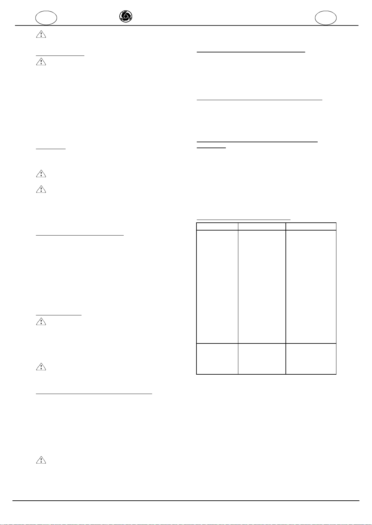
1.DATI TECNICI
Nellatabella1sonoriportatiidatitecnicidellebetoniere,facendo
riferimentoallafigura1.
2.NORMEDIPROGETTO
Lebetonieresonostateprogettateecostruiteapplicando lese-
guentinorme:EN292-1-2;EN60204-1;prEN12151.
3.LIVELLOEMISSIONESONORA
Intabella2sonoriportatiillivellodi pressionesonoradellabetoniera,
misuratoall'orecchio dell'operatore(LpA a1m-98/37/CE)ed livello
di emissionesonoranell'ambiente(potenzaLWA)misuratosecon-
doENISO3744(2000/14/CE).
4.DESCRIZIONEEFUNZIONAMENTOBETONIERA
-Labetonieraèdestinataperl'impiegoneicantie-
riedili,perottenereimpastidicalcestruzzi, malte,
cementizi,ecc.
-Èsconsigliatol'usodellamacchinainambienticon
temperatureinferioria0°C.
BETONIERA CONMOTOREELETTRICO(FIG.1)
La betonieraècostituitadaun telaio(rif.1)condueruoterigide
(rif.2),unbraccio(rif.3)sucui èavvitatoilriduttore(rif. 4),
cheruotapermezzodi una cinghiapoly-V (rif.5),trascinatain
rotazionedal motoreelettrico(rif. 6).
Sul riduttoreèmontatalavascadi mescolamento(rif.7):la
boccoladellavascaèinseritasull'alberod'uscitaconicodel
riduttore,inserendolaspinanell'asoladellaboccoladellava-
sca.Lavascaèbloccatasull'alberodelriduttoreconun'appo-
sitavite.
Ilribaltamentodellavascaècomandatodalla rotazionemanua-
ledel volante(rif.8),cheagiscesul riduttoreruota-vitesenza
fine(rif.9),collegatoalbraccio.
L'accensioneel'arrestodelmotoreelettricoèrealizzatopermezzodi
dueappositipulsantipresentisul quadroelettrico(rif.10).
Sulquadroelettricoèpresentelaspina(rif.11)perilcollegamento
dell'alimentazioneelettrica.
Perlamovimentazionein cantiere(amacchinascarica)èpresenteil
timone(rif.12)chepuòessereestrattodaltelaio.
5.SICUREZZA OPERATIVA
-Prima di utilizzarelabetonieraaccertarsichesia
munitadi tuttiidispositividi protezione.
-E'vietatointrodurrepartidelcorpoe/o utensili
nellavasca dimiscelazionein funzione.
II
TABELLA2
BETONIERA TIPODIMOTORE LpA(dB) LWA(dB)
S190EL
S250EL ELETTRICO 72 84
S300EL
S350EL ELETTRICO 72 84
-TABELLA1-
Modellobetoniera S190EL S 250EL S 300 EL S350 EL
Codicebetoniera: 1105650 1105700 1105703 1105750 1105800 1105803
Capacitàvasca l 190 235 314 345
Capacitàd'impasto(circa) l 160 190 250 280
Resaeffettiva(circa) l 120 140 190 210
N°girivascaalminuto 24 24 24 24
Direzionerotazionevasca Antiorario Antiorario Antiorario Antiorario
Pesomacchina Kg 106 119 173 175
Dimensioneruote mm 295x54 370x85 Ø385X90 Ø385X90
Potenzamotoreelettrico KW 1 1 1,4 1,4
Tensione(monofase) V 230 230 110 230 230 110
Correnteassorbita A 5 5 12 8 8 14.5
Frequenza Hz 50 50 50 50
N°girimotoreelettrico n/1' 2.850 2.850 2.800 2.800
Gradodiprotezione IP55 IP55 IP55 IP55
Lunghezzatotalebetoniera(L) cm 146,5 146,5 161 161
Altezzatotalebetoniera(H) cm 133,4 147,6 157,5 160
Larghezzatotalebetoniera(B) cm 79,3 84 93 93

4
IMERINTERNATIONALS.p.A.
S190-S250 -S300-S350 EL
Nell’area dilavorodevonoessereosservatelenormeperla
prevenzione degliinfortuninonchèledisposizionidisicurezza.
Occorrefareattenzionedurantela manipolazionedeicompo-
nentinecessariallapreparazionedelle maltedi nonsollevare
polvereperevitaredi inalarne;seciò nonfossepossibile è
necessarioindossareunamascheraperlaprotezionedellabocca
edelnaso.
-Nondeveessereusatainambientioveesistaperi-
colodi esplosioni oincendio oin ambientidi scavisot-
terranei.
Labetonieranondisponedi illuminazionepropria epertantoil
luogodilavorodeveesseresufficentementeilluminato.
Le lineedialimentazionedevonoessereposateinmodo taleda
nonpoteresseredanneggiate.Noncollocarelabetonierasul
cavodi alimentazione.
L'allacciamentoelettricodeveesseretaledaimpedirela
penetrazione diacquaneiconnettori.Impiegaresoltanto
connettoried attacchi munitidi protezionecontrogli spruzzi
d’acqua.
-Non utilizzarelineeelettricheinadeguate,provvisorie,privedi
terra:eventualmenteconsultarsiconpersonalespecializzato.
-Le riparazionidegliimpiantielettricidevonoessereeseguite
esclusivamenteda personalespecializzato.Sconnetterela
macchina dall'alimentazione odarrestareil motoreprimadi
eseguirele operazioni di manutenzioneoriparazione.
6.SICUREZZAELETTRICA
LabetonieraIMERèrealizzatasecondo lanormaEN60204-1,
èprotettacontroglispruzzid'acqua(IP 55)edèdotatadi
protezione controisovraccarichiecontroilritorno intempesti-
vodellacorrente.
Puòessereutilecollegarelastrutturametallicadellamacchina
adunimpiantoditerra,usandouncavoequipotenziale(fig.3)
tramitelavite(fig.1,rif.14),inpresenzadicavivolantiin
vicinanzadellamacchina.
Ilpericolodideterioramentodelcavodialimentazionealmotore
elettrico,causatodaattorcigliamento,èeliminatodaunabattu-
tad'arresto(rif.13,fig.1)cheimpediscelarotazione completa
dellavascadimescolamento.
7.SICUREZZAMECCANICA
NellabetonieraIMERipuntipericolosisono protettimediante
opportunidispositividiprotezione,chedevonoesseremante-
nutiin perfettecondizioniemontati,comeadesempiolaprote-
zione della cinghiaditrasmissione.
-ATTENZIONE:ilribaltamentodellavasca di
mescolamentohaunabattutad'arresto(rif.13,fig1)
allarotazionecompleta:evitarediavvicinarepartidel
corpointalezonaduranteilribaltamento.
8.TRASPORTABILITÀ
-Labetonieranondeve esseretrainatasustradada
veicoli, datocheleruotesono adattesolo perspostamenti
neicantiericon vasca di mescolamentovuota.
Perlamovimentazionedellamacchinain cantiere,avendoadisposi-
zione un mezzodisollevamento(paranchi osimili)utilizzaregliappositi
foripresentisul braccio(rif.3,fig.1)peragganciarlaconun cavoa
due ganci:laboccadella vascadeveessererivoltaversoilbasso.
Per la movimentazione manuale della macchina utilizzare il timone (fig.4).
Peril trasportodellamacchinacon fork-lift, utilizzarelesedi specifiche
(rif.15;fig.1).
9.INSTALLAZIONE
La betonieravieneconsegnatagiàprontaperl'uso.
-Installarelabetonierainpiano esufondostabile
(massimainclinazioneammessa 5°,comedaFig.5),per
evitarecheaffondinelterreno osiribaltiduranteil
funzionamento.
Durantel'installazionedellabetonierafarein modochelecarriole
possano essereportatesenzaalcun ostacolosottoallavasca
dimiscelazione peresserecaricate.
10.ALLACCIAMENTOELETTRICO
-
Verificarechelatensionerisulticonformeaidati
ditargadellamacchina,compresatra205 Ve240V,quan-
do èinfunzionecon il caricomax.
Lalinea dialimentazioneelettricadeveessereprovvistadi
protezionecontrolesovracorrenti(es.conun interruttore
magnetotermico)econtroicontattiindiretti(es.conuninterrut-
toretipo differenziale).
-Percollegarelamacchinaaterraoccorreutiliz-
zareuncavo2poli+terra.
Ildimensionamentodeiconduttoridelcavodialimentazione elet-
tricadevetenercontodellecorrentidifunzionamentoedella
lunghezzadellalineaperevitareeccessivecaduteditensione
(rif.Tab.3e4).
Evitarel’impiegodiprolungheavvolteaspiresuitamburi.
Ilconduttoredialimentazionedeveesseredeltipoadattoper
frequentimovimentierivestimentoresistenteall'abrasione (per
esempioH07RN-F).
Collegarel'alimentazioneallaspina dellabetoniera(rif.11,
fig.1),avvitandolaghieradiritegnomeccanicocongradodi
protezione IP67.
-Labetonieraècosìprontaperpoterlavorare.
11.MESSA INMARCIA VERSIONECONMOTORE
ELETTRICO
Collegareilcavodialimentazioneelettricaallaspinadelquadro
elettrico.
Accenderelabetonieramediantel’interruttoreposto
sulquadroelettrico(rif. 10,fig.1),compostodaduetasti:
verdeperl'accensione,rossoperl'arresto.L’interruttoreèdo-
tatodi protezionediminimatensione:nei casiincuisisiaveri-
ficatauna mancanzad'alimentazionepercauseaccidentali,
occorreripremereil pulsanted'avviamentoverde.
Inoltreèdotatodi 2fusibiliperlaprotezione controicortocircuiti:
incasod'interventoènecessario scollegareil cavodialimenta-
zione elettrica,togliereilcoperchiodelquadroelettricosvitan-
dole4viti,sostituireifusibili guasti(dellostessomodello)e
riavvitareilcoperchio.
-Seifusibili siguastano ancora,farcontrollare
l'impiantoelettricodaunelettricistaqualificato.
Incasodiemergenzaarrestarelamacchinapremendo sulpul-
santedi arrestodicolorerosso(sporgente),quindistaccarela
presadialimentazioneelettrica.
PROTEZIONETERMICA:
-
Ilmotoreelettricoèprotettodaisovraccarichidauna
sondatermica:incasodisurriscaldamentosiarresta.Far
raffreddareil motoreedavviaredinuovo.
12.MODALITÀD'USO
Perottenereunamiscelazioneottimaleed un funzionamentore-
golare,labetonieradeveessereinstallataorizzontalmentesele-
zionandol’inclinazionedellavascadimescolamentocorrispon-
denteall’impastodafare.
-Introdurreimateriali con lavasca inrotazione.
L'inclinazionedella vascapuò esserevariataanchedurantela
fasedicaricamentodei materiali,alloscopo dinonfaruscire
l'impasto.
Primadi iniziareadintrodurreimaterialiall'internodellavascaè
convenienteversareuna certaquantitàdi acqua.Ilcaricamento
deveessereeffettuatoalternandoivarimateriali damescola-
re,nellequantitàdesiderateperil tipod’impastochesivuole
ottenere,allo scopo diridurrealminimoiltempo dimescolamento.
Farruotarelavascaperun temponecessario ad ottenereun
impastoomogeneo,dellaconsistenzadesiderata.
Lo svuotamentodeveessereeffettuatoconla vascadi
miscelazioneinfunzione,inclinando laboccadellavascaver-
soil basso,ruotandol'appositovolante(rif.8,fig.1).
I I
5
IMERINTERNATIONALS.p.A.
S190-S250 -S300-S350 EL
-
Èvietatointrodurrepartidelcorpoe/outensili
all'internodellavasca dimiscelazioneinfunzione.
13.MANUTENZIONE
-Leoperazionidimanutenzionedevonoessereese-
guitedapersonaleesperto, dopo averspentoil motore
elettrico, scollegatal'alimentazioneelettrica esvuota-
talavascadimescolamento.
Controllareogniduemesidilavoro:
-tensionamentocinghia(cinghie permotoreendotermico);
-lo statod'usuradella cinghia poly-Vedellepulegge;
-serraggiodellaviteche bloccala vascasulriduttore;
-pulirela carcassadel motoreelettricoda detritiesporcizia;
-lubrificazionecongrassolavitesenza-fineeruotadentata.
Controllaresettimanalmenteche icontattidella spinapostasul
quadroelettricosiano benpuliti,asciuttieprividi ossidazioni.
13.1PULIZIA
Primadiunalungapausadilavorooalterminedellavoroquoti-
diano,lavascadimiscelazionedeveesserepulitaafondo all’in-
ternoed all’esterno.
-Quandosieseguelapuliziamanuale,non sidevemet-
terein funzionelabetoniera.
-Seperlapuliziavengonorimosse lecoperturedi
protezione,allafinedeilavorioccorrerimontarle
correttamente.
Selapuliziavieneeseguitamediantegettid’acqua,nonindiriz-
zarequestiultimidirettamentesul gruppospina-interruttore.
13.2INDICAZIONIPERLAPULIZIA
Pulirelabetonieraall’esterno conunaspazzolaeacqua.Ra-
schiarele incrostazionidicalcestruzzoemalta.
All’internodellavascanon devonoformarsiincrostazionidical-
cestruzzoemalta.L’internodellavascasipuliscemegliose,
primadilunghepausee/oaltermine del lavoro,sifafunzionare
lavascaconalcunepalatedi ghiaiaedacqua.Intalmodosi
impediscel’indurimentodeiresidui dicalcestruzzoomalta.
Lavascadi miscelazionenondeveesserecolpitoconoggetti
duricomemartelli,paleecc.
Lavascadimiscelazioneammac-
catapeggiorailprocedimentodimiscelazioneedèanche più
difficiledapulire
.
13.3RIPARAZIONE
-Non metterein funzionelabetonieraduranteila-
voridi riparazione.
Leriparazioni degli impiantielettricipossono essereeseguite
esclusivamentedapersonalespecializzato.
Iricambi dautilizzaredevonoessereesclusivamentericambiori-
ginali IMERenonpossonoesseremodificati.
-Sepereseguireleriparazioni vengono rimosse le
coperturedi protezione,alterminedeilavoridevonoes-
sererimontatecorrettamente.
14.TENSIONAMENTODELLA CINGHIA (FIG. 6)
La trasmissionedelmotodalmotoreelettrico(rif. 1)al riduttore
della vasca(rif. 2)avvienepermezzodiunacinghia poly-Va6
dentitriangolari(rif. 3).Peril suo tensionamento,occorreprima
di tuttoscollegareilcavodi alimentazioneelettrica,toglierela
protezionedellacinghia (rif. 4)svitandole vitiche labloccano.
Allentarele4viti(rif.5)chebloccanoil supportodelmotore
elettricoal braccio.Tirarelacinghiapermezzodellavite(rif.6):
applicandouna forzadi F=1,5Kgalcentrodel trattoliberodella
cinghia,lafreccia dovràrisultarecircaf=5mm(fig.7).
-Non tirareeccessivamentelacinghia,altrimentisi
riduce lasuavitaequelladeicuscinettidelmotoreelet-
tricoedelriduttore.
Alterminedeltensionamentooccorreserrarele 4viti(rif.5)e
rimontarela protezionedellacinghia(rif.4).
15.SOSTITUZIONEDELLA CINGHIA (FIG. 6)
Procederecomenelpar.15.1,allentandolaviterif.6,finoafare
uscirelacinghiadallepuleggiedelmotoreelettricoedelriduttore.
Inserirelanuovacinghia,primanellapuleggiadelriduttoreepoi
in quelladelmotoreelettrico:fareattenzionechei6dentidella
cinghiasianoinseriticorrettamentenellegoledellepulegge.Pro-
cederequindi altensionamentocomenelparagrafo14.
16.FRENOPERRIBALTAMENTOVASCA (FIG. 8)
Sulla vitesenza-fine del riduttorediribaltamento(rif. 1)sono
montati2freni (rif.2)perimpedirecheil volanteruotiautonoma-
mentequandolavascadi mescolamentoruota.
Seciòaccade,occorresostituirequestifreni,smontandoil
coperchiettorelativo(rif.3).
17.SMONTAGGIOERIMONTAGGIOVASCA DELLA
BETONIERA.
Nelcasosianecessariosmontarelavasca,alsuorimontaggio
ènecessario:
-pulireaccuratamenteil conodell’alberodelriduttoreedil cono
dellavasca.
-montarelavascasul conodell’albero,verificandochelaspina
dell’alberosiadentrolasuasedenelconodella vasca.
-bloccarelavascaserrandolaviteconrondellaconleseguenti
coppie diserraggio.
SYNTESI190-250:22 ±2Kgm.
SYNTESI300-350:30 ±2Kgm.
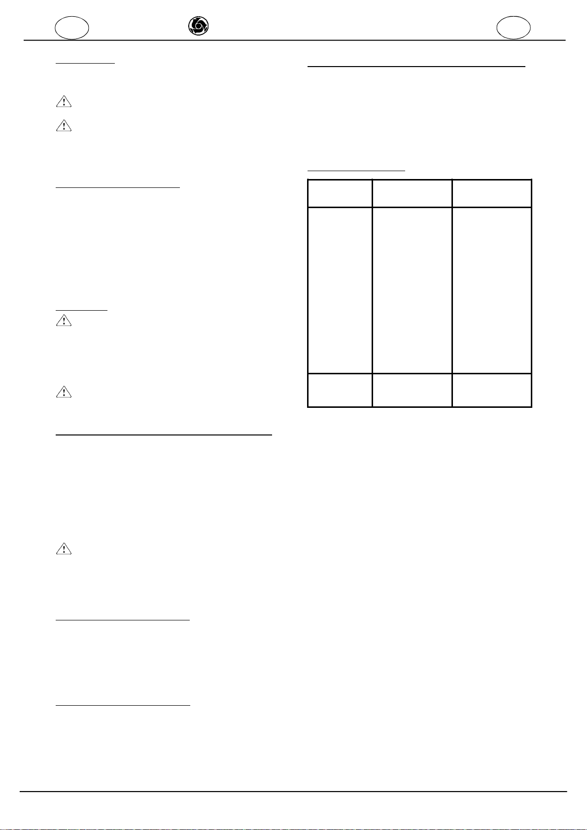
18.INCONVENIENTI/CAUSE/RIMEDI
I I
INCONVENIENTI CAUSE RIMEDI
Premendo
l'interruttoreil
motoreelettrico
nonparte.
-Nonarrivatensione
sullalineadi
alimentazione.
-Lapresaelaspina
elettricanonsono
bencollegate.
-Ilcavodi alimenta-
zionedallaspinaal
quadroèinterrotto
-Unfiloelettrico
all'internodelquadro
èstaccato.
-L'interruttoreè
guasto.
-Fusibileinterrotto
-Éintervenutoil
dispositivodi
protezionetermico.
-Controllarelalinea.
-Ripristinareun
correttocollegamento.
-Cambiarecavo.
-Collegaredi nuovo.
-Cambiarel'inter-
ruttore.
-Cambiareilfusibile
nel quadroelettrico
-Attenderequalche
minutoeriprovaredi
nuovo.
Durante
l'impastoil
numero deigiri
dellavasca
diminuiscono
-lacinghia è
allentataousurata. -Tensionareo
sostituirelacinghia

6
IMERINTERNATIONALS.p.A.
S190-S250 -S300-S350 EL
F
CherClient
Nousvousfélicitonsde votreachat: labétonnièreIMER,résultat
de plusieursannéesd’expérience,estunemachine degrande
fiabilitédotée desolutionstechniquesàl’avant-garde.
OPERERENSECURITE
Ilestfondamental, pourtravaillerentoutesécurité,de
lireattentivementlesinstructionsquisuivent.
LeprésentmanuelUSAGEETENTRETIENdoitêtreconservépar
leresponsableduchantierc’est-à-direlechefdechantieren
personne,etdoittoujoursêtredisponiblepourlaconsultation.
Cemanueldoitêtreconsidérécommepartieintégrantedela
machine etdoitêtreconservépourlesréférencesfutures(EN
292/2)jusqu’à ladestructiondelamachine.Encas
d’endommagementoudeperte,un nouvelexemplairepourra
êtredemandéauconstructeur.
Cemanuelcontientdesindicationsimportantessurlapréparation
du chantier,l’installation,l’utilisation,lesmodalitésd’entretienet
lademandede piècesderechange.Uneexpérienceappropriée
etunebonneconnaissancedelamachinedelapartde
l’installateuretdel’utilisateursontàconsidérercomme
indispensables.
Afin qu’ilsoitpossible de garantirunesécuritéabsolueà
l’opérateur,unesécuritédefonctionnementetunelonguedurée
deviedel’appareil,lesinstructionsdumanueldoiventêtre
respectées,ainsiquelesnormesdesûretéetdeprévention
contrelesaccidentsdu travail selonlaloienvigueur(utilisation
dechaussuresetdevêtementsappropriés,decasques,gants,
lunettesetc.).
-Les signalisationsdoiventtoujoursêtrebienlisibles.
-Il estinterditd’apporterdes modifications,de
quelquenaturequece soit,àlastructuremétalliqueou
àl’ingénieriedelabétonnière.
LasociétéIMERINTERNATIONALdéclinetouteresponsabilitéen
casdenon-respectdesloisrégissantl’utilisationdeces
appareils,enparticulier:usageimpropre,défautsd’alimentation,
manqued’entretien,modificationsnon autorisées,non-respect
partieloutotal desinstructionscontenuesdanscemanuel.
LasociétéIMERINTERNATIONALale droitdemodifierles
caractéristiquesdelabétonnièreet/oulecontenu decemanuel,
sansobligation de mettreàjourla machine et/oulesmanuels
précédents.
1.DONNEESTECHNIQUES
Le tableau1contientlesdonnéestechniquesdesbétonnières,
enseréférantaufigure1.
2.NORMESDEPROJET
Lesbétonnièresontétéconçuesetconstruitesenappliquant
lesnormessuivantes:EN292-1-2;EN60204-1;prEN12151.
3.NIVEAUD’EMISSIONSONORE
Letableau2reportele niveaudepressionacoustiquedela
bétonnière,mesurée àl’oreilledel’opérateur(LpA à1m-98/37/
CE)etleniveaud’émissionsonoredansl’environnement
(puissanceLWA)mesuréd’aprèsENISO3744 (2000/14/CE).
4. DESCRIPTIONETFONCTIONNEMENT
-Labétonnièreestemployée surles chantiersenvue
d’obtenirdesgâchagesdebéton, demortier,deciment,etc.
-L'usagedelamachineestdéconseillédansdesendroits
avectempératuresinférieuresà0°C.
BÉTONNIÈRE AVECMOTEURÉLECTRIQUE(FIG.1)
La bétonnièresecomposed’unchâssis(réf.1)avecdeuxroues
rigides(réf.2),unbras(réf.3)surlequelestvisséleréducteur
(réf.4),qui tourneaumoyen d’unecourroie poly-V(réf.5),
entraînéeenrotationparlemoteurélectrique(réf.6)
Lacuvedemalaxageestmontée(réf.7)estmontéesurle
réducteur:la douilledelacuveestinséréesurl’arbredesortie
conique duréducteur,enintroduisantlafiche dansla fentede
la douilledelacuve.Lacuveestbloquéesurl’arbreduréducteur
avecunevisspéciale.
Le renversementdelacuves’obtienten tournantmanuellement
le volant(réf.8),qui agitsurleréducteurroue-vissansfin
(réf.9),relié au bras.
La miseenmarcheetl’arrêtdumoteurélectrique sontréalisés
au moyende deuxpoussoirsspéciauxinstalléssurletableau
électrique (réf.10).
Lafiche(réf.11)setrouvesurle tableau électriquepourla
connexion del’alimentationélectrique.
Pourlamanutentionsurle chantier(machinevide),onutilisele
timon(réf.12)quipeutêtreextraitdu châssis.
F
TABELLA2
BETONIERA TIPODIMOTORE LpA(dB) LWA(dB)
S190EL
S250EL ELETTRICO 72 84
S300EL
S350EL ELETTRICO 72 84
-TABLEAU1-
Modèlebétonnière: S190 EL S 250 EL S 300 EL S350 EL
Code bétonnière: 1105650 11057001105703 1105750 1105800 1105803
Capacitécuve l 190 235 314 345
Capacitéde malaxage (environ) l 160 190 250 280
Rendementeffectif(environ) l 120 140 190 210
Nombrede tourscuveparminute 24 24 24 24
Directionrotationcuve Sensinverse Sensinverse Sensinverse Sensinverse
Poidsbétonnière Kg 106 119 173 175
Dimensionsroues mm 295x54 370x85 Ø385 X90 Ø385 X90
Puissancemoteurélectrique KW 1 1 1,4 1,4
Tension(monophasée) V 230 230 110 230 230 110
Courantabsorbé A 5 5 12 8 8 14.5
Fréquence Hz 50 50 50 50
Nombrede toursmoteurélectrique n/1' 2.850 2.850 2.800 2.800
Degrédeprotection IP55 IP55 IP55 IP55
Longueurtotalebétonnière(L) cm 146,5 146,5 161 161
Hauteurtotalebétonnière(H) cm 133,4 147,6 157,5 160
Largeurtotalebétonnière(B) cm 79,3 84 93 93
7
IMERINTERNATIONALS.p.A.
S190-S250 -S300-S350 EL
5. SECURITED’UTILISATION
-Avantd’utiliserlabétonnière,contrôlerquetous
lesdispositifsdeprotectionsoientinstallés.
-Il estinterditd’introduiredes parties du corpset/ou
desoutilsdanslacuvedemélangeenmarche.
Dansla zone de travail,lesrèglesdesécuritéetdeprotection
contrelesaccidentsdoiventêtreappliquéesimpérativement.
Durantlamanipulationdescomposantsnécessairesàla
préparationdesmortiers,veillerànepassouleverdepoussière
pourenéviterl’inhalation;sicelaétaitimpossible,porterun masque
deprotectiondela boucheetdunez.
-Ellenedoitpasêtreutiliséedanslesmilieuxà
risquesd’explosionoud’incendienidansdesfouilles
souterraines.
Labétonnièren’estpasilluminée etdonclelieudetravail doitêtre
suffisammentéclairé.
Leslignesélectriquesdoiventêtresinstalléesdefaçonànepas
risquerd’êtreendommagées.Nepasposerlabétonnièresurle
câbled’alimentation.
Lebranchementélectriquedoitêtrefaitdefaçonàempêcherla
pénétration d’eau danslesconnecteurs.
Utiliseruniquementdesconnecteursetdesraccordements
protégésspécifiquementcontrel’eau.
-Nepasutiliserdelignesélectriquesinadaptées,provisoires,
sansmiseàlaterre.Consulterun spécialistelecaséchéant.
-Lesréparationsélectriquesdoiventêtreconfiéesexclusivement
àun personnelspécialisé. Débrancherlamachinedel’alimentation
ouarrêterlemoteuravant touteopérationd’entretienouréparation.
6.SECURITEELECTRIQUE
LabétonnièreIMERestréalisée selonlesnormesEN60204-1,
protégéedesprojectionsd’eau (IP55)etéquipéede protection
contrelessurchargesetle retourimprévuducourant.
Lorsd’uneinstallationsurchantier,raccorderlastructure
métalliquedelamachineàuneinstallationdemiseàlaterreavec
lavis(fig.1,réf.14)àl’aided’unetresse(oucâble)deterrede
16 mm²desectionminimum(fig.3).
Ledangerdedétériorationdu câbled’alimentationaumoteur
électrique,provoqué parunéventuel entortillement,estéliminé
parunebutée d’arrêt(réf.13,fig.1)quiempêchelarotation
complètedelacuvedemalaxage.
7.SECURITEMECANIQUE
DanslabétonnièreIMER,lespointsdangereuxsontprotégés
pardesdispositifsde protectionopportuns,qui doiventêtre
maintenusdansdeparfaitesconditionsetmontés,commepar
exemplela protectiondelacourroie detransmission.
-ATTENTION:lerenversementdelacuve demalaxage
estéquipéd’unebutée d’arrêt(réf.13,fig.1)contrela
rotation complète:éviterdevousapprocherdecet
endroitpendantledéversement.
8.TRANSPORT
-Labétonnièrenedoitpasêtretraînéesurroute
pardes véhicules,ses roues étantconçues uniquement
pourdes déplacementssurleschantiersaveccuve de
malaxagevide.
Pourlamanutentiondesmachinessurchantier,ayantàdispositionun
moyendelevage (palanousimilaire)utiliserlestrousprévussurle
bras(réf.3,fig.1)pourl’accrocheravecun câbleàdeuxcrochets: la
bouchedelacuvedoitêtretournée verslebas.
Pourlamanutentionmanuelledelamachine,utiliserletimon (fig.4).
Pourle dèplacementdelamachinepar"forklift",utiliserlespoints
d'ancorage(réf.15;fig.1).
9.INSTALLATION
Labétonnièreestlivrée prêteàl’emploi.
-Installerlabétonnièreàplatsurfond stable
(inclinaison maximumadmise 5°,comme indiquésurla
fig. 5)pouréviterquelamachinenes’enfonce ou nese
renverse encoursdefonctionnement.
Lorsde l’installation delabétonnière,veilleràcequeles
brouettespuissentarriversansproblèmesouslacuvede
malaxage pourle remplissage.
10.BRANCHEMENTELECTRIQUE
-Vérifierquelatension delignesoitconforme aux
donnéessurlaplaquedelamachine,comprise entre205
et24OV,lorsqu’ellefonctionneavec unecharge
maximum.
Laligned’alimentationélectriquedoitêtredotéede protection
contrelessurintensités(ex.avecun interrupteur
magnétothermique)etcontrelescontactsindirects(ex.avecun
interrupteurdifférentiel).Relierlamachine àl’installation de la
miseàlaterre.Lesconducteursd’alimentationélectrique
devronttenircomptedescourantsde fonctionnementetde
lalongueurdelaligneafin d’éviterleschutesexcessivesde
tension(réf.Tab.3et4).
Eviterl’emploiderallongesenrouléesenspiralesurdestambours.
Leconducteurd’alimentationdoitêtreconçupouraccomplirdes
mouvementsfréquentsetêtrerésistantàl’abrasion(parexemple
H07RN-F).
Raccorderl’alimentationàlaprisedela bétonnière
(réf.11,fig.1),envissantlabaguederetenuemécaniqueavec
un degrédeprotectionIP67.
-Labétonnièreestalorsprêteàtravailler.
11.MISEENMARCHEVERSION AVECMOTEUR
ELECTRIQUE
Relierle câbled’alimentationélectriqueàlafichedutableau
électrique.Mettrelabétonnièreen marcheaumoyende
l’interrupteursitué surletableauélectrique(réf.10,fig.1)
composédedeuxtouches:vertepourla miseen marche,
rougepourl’arrêt. L’interrupteurestdotédeprotectionpour
tension minimum:encasdecoupureaccidentelle decourant,
appuyerde nouveau surleboutondemiseenmarchevert.
Deplus,il estdotéde2fusiblespourla protectioncontre
lescourts-circuits:encasd’intervention,il faut
débrancherlecâbled’alimentationélectrique,enleverle
couvercledu tableau électriqueendévissantles4vis,
remplacerlesfusiblesayantsauté(dumêmemodèle)et
revisserlecouvercle.
-Siles fusibles sautentdenouveau, fairecontrôler
l’installationélectriqueparun électricienqualifié.
Encasd’urgence,arrêterlamachineenappuyantsurlebouton
d’arrêtdecouleurrouge(saillant),puisdébrancherlafiche.
PROTECTIONTHERMIQUE
-Lemoteurélectriqueestprotégécontreles
surcharges parunesondethermique;encas desurchauffe,
il s’arrête.Laisserrefroidiretredémarrer.
12.MODED’EMPLOI
Afin d’obtenirun malaxageoptimaletun fonctionnementrégulier,
labétonnièredoitêtreinstallée horizontalementaprèsavoirchoisi
l’inclinaisondelacuveselonlemélangeàréaliser.
-Introduirelesmatériauxaveclacuve enrotation.
L’inclinaisonde lacuvepeutêtrechangéeégalementenphase
de chargementdesmatériaux,afinde nepasfairesortirle
mélange.
Avantd’introduirelesmatériauxàl’intérieurdelacuve,il convient
de verserunecertainequantitéd’eau.Effectuerlechargement
enalternantlesdifférentsmatériauxàmélanger,dansles
quantitéssouhaitéespourletypedemélangequ’onveutobtenir,
danslebutderéduireaumaximumletempsdebrassage.
Fairetournerlacuvejusqu’àl’obtentiond’un mélangehomogène,
dela consistancedésirée.
FF

8
IMERINTERNATIONALS.p.A.
S190-S250 -S300-S350 EL
Lavidange s’effectueenfaisanttournerla cuvede
malaxage,aprèsavoirinclinécelle-civerslebasàl’aide
du volant(réf.8,fig.1).
-Il estinterditd’introduiredesparties du corpset/ou
desoutilsdanslacuvedemélangeenmarche.
13.ENTRETIEN
-Lesopérationsd’entretiendoiventêtreréalisées
parun personnelexpert,aprèsavoiréteintlemoteur
électrique,déconnectél’alimentationélectriqueetvidé
lacuve demalaxage.
Contrôlertouslesdeuxd’utilisation:
-latensiondelacourroie(courroiespourmoteurendothermique);
-l’étatd’usuredela courroiepoly-V etdespoulies;
-leserragedelavisqui bloquelacuvesurleréducteur;
-nettoyerlacarcassedu moteurélectriqueenéliminantlesdétritus
etlesimpuretés;
-lubrification avecgraissede la vissansfinetdela roue
dentée.
Contrôlerchaquesemaineque lescontactsdela fiche située
surletableauélectriquesontbienpropres,secsetne présentent
pasdetracesd’oxydation.
13.1NETTOYAGE
Avantunelonguepausedetravail ou àlafin du travailquotidien,la
cuvedemalaxagedoitêtrenettoyée àfond,àl’intérieuretàl’extérieur.
-Pourprocéderaunettoyagemanuel, il est
nécessaired’arrêterlabétonnière.
Si,pourfaciliterlenettoyagelescarénages deprotection
sontenlevés,il estnécessairedelesremonter
correctementàlafin destravaux.
Silenettoyageesteffectué aumoyendejetsd’eau,nepasles
dirigerdirectementsurlegroupefiche-interrupteur.
13.2INDICATIONSPOUR LENETTOYAGE
Nettoyerlabétonnièreàl’extérieuravecunebrosseetde l’eau.
Raclerlesincrustationsdebétonetmortier.
Al’intérieurdelacuve,il nedoityavoird’incrustationsdebéton
etdemortier.
Ilestplusfacile de nettoyerl’intérieurdelacuvesi,avantde
longuespauseset/ouàlafin du travail,onfaitfonctionnercette
dernièreavecquelquespelletéesdegravieretdel’eau.Decette
façon,onévitele durcissementdesrésidusdebétonou de
mortier.
La cuvede malaxagenedoitpasêtrefrappée avecdesobjets
durstelsque marteaux,pelles,etc.. Unecuvedemalaxage
bosselée nuitauprocessusdemalaxageet,deplus,elleest
plusdifficile ànettoyer.
13.3REPARATION
Nepas mettrelabétonnièreenservice pendantles
travauxderéparation.
Lesréparationsauniveau desinstallationsélectriquesdoivent
êtreeffectuéesexclusivementpardupersonnelspécialisé.
Lespiècesderechangeutiliséesdoiventêtreexclusivementdes
piècesderechangeoriginalesIMERetnepeuventêtremodifiées.
-Si, poureffectuerles préparations,les carénages
deprotectionsontenlevés,ilsdoiventêtreremontés
correctementàlafin destravaux.
14.TENSIONDELA COURROIE(FIG. 6)
La transmissiondumouvementparlemoteurélectrique(réf.1)
auréducteurdelacuve(réf.2)alieuaumoyen d’une courroie
poly-Và6dentstriangulaires(réf. 3)Pourexécuterlatension,
débrancheravanttoutlecâbled’alimentationélectrique,enlever
laprotectiondelacourroie(réf.4)endévissantlesvisquila
bloquent.
Desserrerles4vis(réf.5)qui bloquentle supportdu moteur
électriqueaubras.Tirerlacourroieaumoyendelavis(réf.6)en
appliquantuneforcedeF=1,5Kgaucentredelapartielibrede
lacourroie;laflèche devraêtredef=5mm environ(fig.7).
F F
-Nepastirerexcessivementlacourroie,pouréviter
deréduiresadurée devieetcelledesroulementsdu
moteurélectriqueetdu réducteur.
Ala fin delatension,serrerles4vis(réf.5)etremonterla
protection de lacourroie (réf.4).
15.REMPLACEMENTDELA COURROIE(FIG. 6)
Procédercommeindiqué auparagraphe15.1,endesserrantla
visréf.6,jusqu’à fairesortirlacourroiedespouliesdumoteur
électriqueetdu réducteur.Insérerlacourroieneuve,toutd’abord
danslapouliedu réducteurpuisdanscelledu moteurélectrique:
s’assurerque les6dentsde lacourroiesoientinsérées
correctementdanslesgorgesdespoulies.
Procéderenfin àlatensioncommeindiquéauparagraphe14.
16.FREINPOURRENVERSEMENTCUVE(FIG.8)
Surlavissansfinduréducteurderenversement(réf.1),2
freinssontinstallés(réf.2)afind’empêcherquelevolanttourne
de façon autonomelorsque la cuvede malaxagetourne.
Sicelaseproduit, remplacercesfreins, endémontant lecouvercle
correspondant(réf.3).
17.DÉMONTAGEETREMONTAGECUVEBÉTONNIÈRE
-Aucasoùsoitnécessairedémonterlacuve,pourlaremonteril faut:
-nettoyersoigneusementlecône del’arbreduréducteuretle
cônede cuve
-monterlacuvesurlecônedel’arbre,vérifiantquelegoujonsoit
àl’interieurdeson logementdanslecônedecuve.
-Bloquerlacuveserrantlavisavecla rondelleparlescouples
deserragesuivantes.
SYNTESI190-250:22 ±2Kgm.
SYNTESI300-350:30 ±2Kgm.
18.INCONVENIENTS/CAUSES/REMEDES
INCONVENIENT CAUSES REMEDES
Enappuyantsur
l'interrupteur,le
moteur ne
démarre.
-Latensionn'arrive
passurlaligne
d'alimentation.
-Lapriseetlafiche
électriquenesont
pasbranchées
correctement.
-Lecâble
d'alimentationdela
ficheautableauest
interrompu.
-Unfilélectrique
s'estdébranchéà
l'intérieurdutableau.
-Unfilélectriqueest
débranchéà
l'intérieurdubornier
moteur.
-L'interrupteuresten
panne.
-fusibleinterrompu
-Ledispositifde
protectionthermique
estintervenu.
-Contrôlerlaligne.
-Rétablirle
branchementcorrect.
-Changerlecâble.
-Rebrancher.
-Rebrancher.
-Changer
l'interrupteur
-changerlefusible
dansletableau
électrique
-Attendrequelques
minutespuisessayer
ànoveau.
Pendantle
malaxage,lestours
ducuvede
malaxage
diminuent.
-Lacourroieest
desserréeouusée -Tendreou
remplacerlacourroie

9
IMERINTERNATIONALS.p.A.
S190-S250 -S300-S350 EL
GB GB
Dearcustomer,
congratulationsonyourchoiceofpurchase:theIMERCON-
CRETEMIXER,the resultofyearsofexperience,isavery
reliablemachine equippedwithall thelatesttechnical
innovations.
WORKINGINSAFETY
In ordertobeabletoworkin completesafety,thefollowing
instructionsmustbereadcarefully.
ThisOPERATINGAND MAINTENANCEmanualmustbekepton
sitebythepersonresponsiblefortheworksite,e.g.thesite
foreman,andmustalwaysbe availableforconsultation.
Themanualshould beconsideredasbeing anintegralpartofthe
machine,and mustbekeptforfuturereference(EN292/2)until
themachineitselfisdisposedof.If themanualbecomesdamaged
orlost,areplacementcanbeobtainedfromthemanufacturer.
Themanualcontainsimportantinformationregarding thesite
preparation,installation,useofthemachine,maintenanceand
sparepartsordering.Nevertheless,theinstallerandusermust
bothhaveadequateexperienceandknowledge ofthemachine.
Inorderthatthesafetyoftheoperator,safeworking and long life
oftheequipmentcanallbeguaranteed,theinstructionsinthis
manualmustbefollowed togetherwithsafetystandardsand
healthand safetyatworklawscurrentlyin force(useofsuitable
footwearand clothing,useofhelmets,glovesand goggles,etc.).
-Alwaysmake surethatsignsarelegible
-Itisstrictlyforbiddentocarryoutanyformof
modification tothestructureorworking partsofthe
machine.
IMERINTERNATIONALdeclineanyresponsibilityin thecaseof
non-compliancewithlawsandstandardsgoverningtheuseof
thisequipment. Inparticular:improperuse, defectivepowersupply,
lackofmaintenance,unauthorisedmodifications,partial ortotal
failuretocomplywithinstructionscontained in thismanual.
IMERreservestherighttomodifythecharacteristics ofthecon-
cretemixerand/orthecontentsofthismanualwithoutany
obligation toupdatepreviousmachinesormanuals.
1.TECHNICAL SPECIFICATIONS
Table1reportsthetechnicalspecificationsoftheconcretemixer,
withreferencetofigure1.
2.DESIGNSTANDARDS
The concretemixershavebeendesigned andbuiltin accordance
withthefollowing standards:EN292-1-2,EN60204-1,prEN12151.
3.NOISE EMISSIONLEVEL
Table2indicatesthenoiselevelproducedbythemixer, measured
attheoperator’sear(LpA at1m-98/37CE) and theenvironmental
noiseemissionlevel (powerLWA)measured inaccordancewith
ENISO3744 (2000/14/CE).
4.DESCRIPTION ANDOPERATION
-Theconcretemixerisdesignedforuse on
constructionsites,forpreparingandmixingconcrete,
mortars,cementmixes,etc.
-Useofthemachineisunadvisablewithtemperatures
below0°C.
CEMENTMIXERWITHELECTRICMOTOR(FIG. 1)
Thecementmixercomprisesaframe(ref.1)withtwohardwheels
(ref. 2),anarm(ref.3)ontowhichthe gearunitisattached(ref.4),
drivenbyapoly-V belt(ref.5)whichisdrivenin turnbytheelectric
motor(ref.6).
Themixingdrum(ref.7)ismounted onthe gearunit: thedrumbushis
fitted ontothegearbox’staperedoutputshaftbyinserting thepininto
thesloton thedrumbush.Themixingdrumissecuredontothegear
shaft usingascrew.
Drumtilting iscontrolledbymanual rotationofthehandwheel (ref.8),
whichactsontheworm–wheelgearunit(ref.9),connectedtothe
arm.
Theelectricmotorisswitchedon and off using thetwopushbuttons
ontheelectriccontrolpanel(ref.10).
Theelectriccontrolpanelhasaplug (ref. 11)forconnectiontopower
supply.
Totransporttheconcretemixeron site(withdrumempty)usethe
steering gear(ref.12)whichcanbeextractedfromtheframe.
5.SAFETYINSTRUCTIONS
-Beforeusingmachineensureall safetydevices
arefitted
-Keepall partsofbodyand/ortoolsclearof
mixingdrumduringoperation.
Accidentprevention standardsand safetyregulationsmustbe
observed atalltimesinthe workarea.
Whenhandlingthecomponentsrequiredtopreparethe mixes,
TABLE2
CONCRETE
MIXER TYPEOFMOTOR LpA(dB) LWA(dB)
S190EL
S250EL ELECTRIC 72 84
S300EL
S350EL ELECTRIC 72 84
-TABLE1-
Concretemixermodel S190 EL S 250 EL S 300EL S 350 EL
Concretemixercode 1105650 11057001105703 1105750 1105800 1105803
Drumcapacity l 190 235 314 345
Mixcapacity l 160 190 250 280
Effectiveoutput l 120 140 190 210
Numberofdrumrpm's 24 24 24 24
Directionofdrumrotation Anti-clockwise Anti-clock wise Anti-clockwise Anti-clock wise
Concretemixerweight Kg 106 119 173 175
Wheeldimensions mm 295x54 370x85 Ø385 X90 Ø385 X90
.Electricmotorpower
KW 1 1 1,4 1,4
Voltage (singlephase) V 230 230 110 230 230 110
Nominalcurrent A 5 5 12 8 8 14.5
Frequency Hz 50 50 50 50
Numberofelectricmotorrpm's n/1' 2.850 2.850 2.800 2.800
Protectiongrade IP55 IP55 IP55 IP55
Totalconcretemixerlength(L) cm 146,5 146,5 161 161
Totalconcretemixerheight(H) cm 133,4 147,6 157,5 160
Totalconcretemixerwidth(B) cm 79,3 84 93 93
10
IMERINTERNATIONALS.p.A.
S190-S250 -S300-S350 EL
GB GB
takecarenottoraisedustthatmightbeinhaled;shoulditbe
impossibletoavoid this,wearaprotectivemaskoverthe mouth
andnose.
- Theconcretemixermustneverbeusedinareas at
risk forexplosionsorfires,orin underground excavations.
Theconcretemixerisnotequippedwithlights,and thereforethe
area whereitisusedmustbe well-lit.
Powersupplylinesmustbeinstalledwheretheywillnotbe
subjecttodamage.Donotposition concretemixeroverpower
supplycable.
Connectionmustavoid anycontactofplugswithwater.Only
useplugsandsocketswithprotectionagainstwaterspray.
-Donotuseelectricallinesthatareundersized,makeshiftor
withoutthe earthwire.Consultqualifiedelectricianifuncertain.
-Repairstotheelectricalinstallationmustonlybecarriedoutby
qualifiedpersonnel.Disconnectmachinefrompowersupplyand
stopmotorbeforestarting anymaintenanceoperationsorrepairs.
6.ELECTRICALSAFETY
TheIMERconcretemixerhasbeenproducedin compliancewith
EN60204-1standards,and isprotectedagainstwaterspray
(IP55).Itisalsofitted withprotectiondevicesagainstvoltage
drops/surgesoroverloading.
Forinstallation on building sitesconnectthemetalstructureof
machinetoearthingdevicebymeansofthescrew(fig.1ref.
14)and anearthbraid (orcable)withaminimumsectionof16
mm²(fig.3).
Theriskofdeteriorationofthepowercabletotheelectricmotor
duetotwisting ispreventedbyastop(ref.13,fig.1)which
preventsthecompleterotationofthemixing drum.
7.MECHANICALSAFETY
All dangerousareasontheIMERconcretemixerhaveprotective
casingwhichmustbekeptinstalled atalltimesandmaintainedin
perfectcondition,e.g.thedrivebeltguard.
ATTENTION:Tiltingofthemixing drumisregulated
byastop(ref.13fig.1)atfull rotation. Donotallowany
partsofthebodytobeinthevicinityofthisareaduring
tilting.
8.TRANSPORT
-Theconcretemixermustnotbetowedon theroadbya
vehicle,sinceitswheelsareonlysuitablefortransporting the
mixeronthebuildingsite,withthemixingdrumempty.
Fortransportonthebuildingsitewithlifting equipment(hoistor
similar),usetheholesprovidedforthispurposeonthearm(ref.
3,fig.1)tohookitup toadouble-hookedcable:themouthofthe
drummustbepointeddownwards.
Movemixermanuallybymeansofthesteeringgear(fig.4).
Formoving themachinebyfork-lift, usetheanchorpoints(ref.15;
fig.1).
9.INSTALLATION
Themixerisdeliveredreadyforuse.
-Installmachineonflatand solidground(maximum
admissiblegradient: 5°;see fig. 5)topreventthemixer
feetfromsinkingintothegroundortopreventthemixer
fromoverturningduringoperation.
During mixerinstallation ensureeasyaccess forbarrowsunder
themixerdrumforloading.
10.ELECTRICALCONNECTION
-Ensurethatmainsvoltagecorrespondstorated
machinevoltage;205Vto240Vwhenthemachineis
operatingwithafull load.
Themachinepowersupplymustbefittedwithoverloadprotection
(athermal-magneticcircuit-breaker)andindirectcontact
protection(aresidualcurrenttypecircuit-breaker,forexample).
Themachinemustbeconnectedtoanearthing system.The
powerleadsmustbe sufficientlysizedtotakeoperating current
andcable lengthintoaccount,inordertoavoidriskofvoltage
drops(ref.table3and 4)
Donotuseextensioncableslooped around thedrum.
Thepowerleadmustbethetypesuitableforfrequentmovement,
withabrasion-resistantsheathing(forexample HO7RN-F).
Connecttheconcretemixerplugtothe powersupply(ref.11,
fig.1).Tightenthering nuttosecurethecurrentsupplyplug and
provideIP67protection.
-Theconcretemixerisnowreadyforoperation.
11.ELECTRICMOTORSTART-UP
Connectthepowersupplycabletotheelectricpanelplug.Turn
onthe concretemixerusingtheswitchlocatedon theelectric
controlpanel(ref.10.fig.1)comprisingtwobuttons:thegreen
oneswitchesonthemachine,whiletheredoneswitchesitoff.
Theswitchhasminimumvoltageprotection:afterapowerfailure
oraccidentalpowerloss,pushthe greenstartbutton tostart
themachineup again.Thepanelisalsoequippedwith2fuses
forshortcircuitprotection:ifthefusestripoff, disconnectthe
powercable,removethecoverofthe electriccontrol panel by
looseningthefourscrews,replacetheburnedoutfuses(same
model)andreplacethe covertighteningthe screws.
-Ifthefuses trip off again, have theelectricalsystem
checkedbyaqualifiedelectrician.
Incaseofanemergency,stopthemachinebypressing thered
stopbutton(extended),thendisconnecttheplug fromthepower
supplysocket.
THERMALPROTECTION:
Theelectricmotorisprotectedfromoverloadsbya
thermalsensor:ifoverheatingoccurs,themotorstops.Let
themotorcooldownbeforeattemptingtostartitupagain.
12.USE
Forperfectmixing and troublefree operation,the mixermustbe
installedhorizontally,selecting thetiltanglesuitableforthetype
ofmixrequired.
-Insertmaterialswhilethedrumisturning.
Drumtiltmaybe adjustedwhilematerialsarebeingloaded,in
ordertokeepthemixfromdripping outofthedrum.
Beforebeginning toloadthematerialsinsidethedrum,itisbest
topouracertain quantityofwaterin first. Whenloading,insert
thevariousmaterialstobemixedalternately,in theamounts
requiredforthetypeofmixtobeobtained,soastoreducethe
mixing timetoaminimum.
Keep thedrumrunninguntilasmoothmixhavingthe desired
consistencyisobtained.
Themixmustbeemptiedwiththemachinein rotation,tilting the
drumdownwardsbyturning the handwheelprovidedforthis
purpose(ref. 8,fig.1).
-Donotintroduce partsofbodyand/ortoolsinside
themixerdrumwhileitisrunning.
13.MAINTENANCE
-All maintenance operationsmustbedoneby
experiencedpersonnel, afterhaving shutdownthemotor,
disconnectedpowersupplyand emptiedthemixingdrum.
Everytwoworking months,checkthe following:
-belttension(internalcombustionenginebelt),
-signsofwearonthepoly-Vbeltorthepulleys,
-tightening ofthescrewssecuring thedrumontothegearunit,
-cleanthe electricmotorcasing,removing dirtand deposits,
-lubricatethewormscrewandgearteethwithgrease.
Check onaweeklybasisthatthe contactsofthe plugand
socketconnectoronthe electricalpanelareclean,dryandfree
ofrust.
11
IMERINTERNATIONALS.p.A.
S190-S250 -S300-S350 EL
GB GB
13.1CLEANING
Aftereachdailyworksessionorbeforelong periodsofinactivity,
themixing drummustbecleanedthoroughlybothinside and
outside.
-Donotstartthemixerwhilecarrying outcleaning
operations.
-Iftheprotection guardsareremovedforcleaning,
alwaysreplacethem correctlyattheendofthecleaning
operation.
Whenusing ahoseforcleaning,donotdirectthesprayintothe
plug-switchunit.
13.2CLEANINGINSTRUCTIONS
Clean the outsideofthemixerwithabrushandwater.Scrape
offanycementorconcretedeposits.
Thereshould notbeanydepositsofcementorconcreteinside
thedrum.Theinsideofthedrumcanbecleanedbetterif,atthe
end oftheworksessionorbeforeaprolongedperiodofinactivity,
thedrumisrotated withafewshovel-fullsofgravel andwater.
Thiswill preventanyresidueofcementorconcretefrom
hardening.
The mixingdrummustnotbestruckwithhardobjectssuchas
hammersorshovels,etc.Adenteddrumwill reducethe mixing
effectsandmakecleaningmoredifficult.
13.3REPAIRS
Donotstartupthemixerwhilerepairsarebeing
carriedout.
Repairstoelectricalsystemsmustbecarriedoutexclusivelyby
specialiststaff.
OriginalIMERsparepartsonlymustbeusedandmustnotbe
modified inanyway.
-Iftheprotectionguardsareremovedduringrepair
operations,theymustbecorrectlyreplacedwhenrepairs
arecompleted.
14.TENSIONINGOFTHETRANSMISSIONBELT(FIG. 6)
Poweristransmittedbytheelectricmotor(ref.1)tothe
mixing drumgearbox(ref.2)bymeansofapoly-Vbeltwith
sixtriangularteeth(ref.3).Tocorrectlytensionthebelt, first
disconnectthepowersupplycable,and then removethe
beltguard(ref.4)bylooseningthescrewswhichsecureit
in place.
Loosenthe 4screws(ref.5)thatsecurethe electricmotor
mounting tothearm.Stretchthebeltusing thescrew(ref.
6):applyaforceofF=1,5Kgatthecentreofthefree section
ofthebelt; thedeflectionshould beaboutf=5 mm (fig.7).
-Donotstretchthebeltexcessively;thiswill
reduce beltlife,as well as thelifeofthegearbox
and electricmotorbearings.
Aftertensioning thebelt, tightenthefourscrews(ref.5)and
replacethebeltguard(ref.4).
15.REPLACINGTHEBELT(FIG.6)
Proceedasinparagraph 15.1,looseningscrewref. 6,until
thebeltcomesoffthepulleysofthe electricmotorand
gearbox.Insertthenewbelt, firstonthegearboxpulleyand
thenontheelectricmotorpulley:takecarethatthesixteeth
ofthebeltarecorrectlyinsertedin thepulleyraces.Proceed
withtensioning thebeltasdescribedin paragraph 14.
16.DRUMTILTINGBRAKE(FIG.8)
Twobrakes(ref.2)aremountedon the wormscrewonthe
tilting gearbox(ref.1),topreventthehandwheelfromturning
freelyasthemixing drumisturning.
Ifthisshould happen,thesetwobrakesshould bereplaced,by
removingtherelativecover(ref.3).
17.MIXER’SDRUMDISASSEMBLY AND RE-ASSEMBLY
-Incaseit’snecessarytoremovethedrum,toresetitit’s
necessary.
-tocleancarefullythe gearshaft cone and thedrumcone.
-toplacethe drumon the shaftcone,makingsurethatshaft
shearpin isinsideitsseatin thedrumcone.
-toblockdrumtighting screwwithwasherbyfollowing tighting
torques:
SYNTESI190-250:22 ±2Kgm.
SYNTESI300-350:30 ±2Kgm.
18.TROUBLESHOOTING
PROBLEM CAUSE REMEDY
Themotor
does notrun
whenthe
switch is
pressed.
-Nopowerinthe
supplyline.
-Theelectricplug
andsocketarenot
connected properly.
-Thecablefromthe
plugtotheelectric
panelisbroken.
-Awirehasbecome
disconnected onthe
terminalboard.
-Theswitchisfaulty.
-Tripped fuse
-Theterrmal
protectiondevice
hasbeentripped.
-Check theline.
-Makeaproper
connection.
-Replacethecable.
-Remakethe
connection.
-Replacetheswitch.
-Change fusein
electricpanel.
-Waitafewminutes
andtryagain.
During mixing
themixerdrum
rpmdecreases.
-Beltsarewornor
slack -Tensionorreplace
thebelts

12
IMERINTERNATIONALS.p.A.
S190-S250 -S300-S350 EL
DD
VerehrterKunde,
WirbeglückwünschenSie zuIhrerWahl:der BETONMISCHERIMERist das
Ergebniseinerlangjährigen Erfahrung,bietethöchsteZuverlässigkeitundist mit
innovativentechnischenLösungenausgestattet.
-SICHERHEIT BEIDERARBEIT
AusSicherheitsgründensolltendiefolgenden
Anleitungenunbedingtsorgfältig durchgelesenwerden.
DasvorliegendeHandbuchGEBRAUCH UND WARTUNGmuss
vomBaustellenleiteraufbewahrtwerden und aufderBaustelle
stetsfüreventuellesNachschlagenzurVerfügungstehen.Das
HandbuchistTeil derMaschineund muss biszumVerschrotten
derselben fürspäteresNachlesen(EN292/2)aufbewahrt
werden.ImFalledesVerlustesoderderBeschädigung kann
vomHerstellerderMaschineein neuesExemplarangefordert
werden.DasHandbuchenthältwichtigeHinweisefürdie
Baustellenvorbereitung,dieInstallation,denEinsatz,dieWartung
und dieErsatzteilbestellung.DerAnwenderund derMonteur
solltenin jedemFall überausreichende Erfahrung und Kenntnis
derMaschineverfügen.FürdieSicherheitdes
Bedienungspersonals,füreinesichereund einwandfreie
Arbeitsweiseund einelangeLebensdauerderMaschinemüssen
dieAnleitungen desHandbuchsunddie einschlägigen
BestimmungenüberSicherheitund Unfallverhütung am
Arbeitsplatz(GebrauchspeziellerSchuheundKleidung,
Schutzhelme,Handschuhe und Schutzbrillen)entsprechendder
gültigenGesetzgebung unbedingteingehaltenwerden.
-HaltenSiealleWarnschilderstetsperfektlesbar..
-AnderMetallstrukturoderdenAnlagenteilender
MaschinedürfenkeinerleiÄbänderungenvorgenommen
werden.
IMERINTERNATIONALübernimmtkeine Haftung,fallsdieGesetze
überdenEinsatzvonMaschinenaufderBaustellenicht
eingehalten werden,undganzbesondersbeiunsachgemäßer
Benutzung,falschemelektrischenAnschluss,mangelnder
Wartung,nichtautorisierten Änderungen,sowie teilweiseroder
vollkommenerNichteinhaltung derin diesemHandbuch
enthaltenenAnleitungen.
IMERINTERNATIONALkann jederzeit und ohneVorankündigung
dietechnischenEigenschaftendesBetonmischersund denInhalt
desHandbuchsändern,ohneVerpflichtung die Maschineund
dievorangehendenAusgaben desHandbuchszuaktualisieren.
1.TECHNISCHEMERKMALE
InderTabelle1sind dietechnischenMerkmaledesBetonmischers
aufgeführt(sieheAbbildung1).
2.PROJEKTNORMEN
DieBetonmischersind unterAnwendung derNormenEN292-1-
2;EN60204-1;prEN12151 entwickeltund gebautworden.
3.SCHALLPEGEL
DieTabelle2enthältdieDaten desaufOhrenhöhedesBedieners
gemessenen Schalldrucks desBetonmischers(LpA in 1mAbstand -
98/37/CE) und die Schallemissionin derUmwelt(SchallleistungLWA),
dienachENISO3744 (2000/14/CE)gemessenwurde.
4.BESCHREIBUNGUNDARBEITSWEISE
-DerBetonmischeristfürdieVerwendung auf
Baustellenbestimmtund fürdieHerstellung von Beton,
Mörtel-und Zementmischungen.
-DieMaschinesolltenichtin Umgebungenmit
Temperaturenunter0°Cbenutztwerden.
BETONMISCHERMITELEKTROMOTOR(ABB.1)
DerBetonmischerbestehtauseinemRahmen(Bez.1)mitzwei
festeingebautenRädern(Bez.2),einemArm(Bez.3),aufdem
dasUntersetzungsgetriebe(Bez.4)festgeschraubtist,dasüber
einenPoly-VKeilriemen(Bez.5)vondemElektromotor(Bez.6)
angetriebenwird.DieMischtrommel(Bez.7)istaufdas
Untersetzungsgetriebemontiert:dieBuchsederMischtrommel
istaufdie konischeAbtriebswelledesUntersetzungsgetriebes
aufgesetztund wirddurchEinführung desSplintesin dasLoch
derTrommelbuchsebefestigt. DieMischtrommelistaufder
Getriebewelle durcheine Schraubeblockiert.DasKippen der
MischtrommelerfolgtdurchmanuellesDrehen desHandrads
(Bez.8),dasaufdenZahnkranzund dieSchnecke(Bez.9)des
mitdemArmverbundenen Untersetzungsgetriebeseinwirkt.
DasAnlassenundAnhaltendesElektromotorserfolgendurch
Drückenderbeidenentsprechenden Druckknöpfeaufder
elektrischenSchalttafel(Bez.10).Aufderelektrischen
SchalttafelbefindetsichauchderSteckerfürdenelektrischen
Anschluss (Bez.11).FürdasBewegenaufderBaustelle(bei
leererMaschine)kanndieausziehbareDeichsel (Bez.12)benutzt
werden.
TABELLE2
BETONMISCHER MOTORTYP LpA(dB) LWA(dB)
S190EL
S250EL ELEKTROMOTORS 72 84
S300EL
S350EL ELEKTROMOTORS 72 84
-TABELLE1-
ModelldesBetonmischers: S190 EL S 250EL S300EL S350EL
CodenummerdesBetonmischers: 1105650 1105700 1105703 1105750 1105800 1105803
VolumenderMischtrommel: l 190 235 314 345
Mischleistung: l 160 190 250 280
Istleistung: l 120 140 190 210
DrehzahlderMischtrommel(proMinute): 24 24 24 24
DrehrichtungderMischtrommel: Entgegendem
Uhrzeigersinn Entgegendem
Uhrzeigersinn Entgegendem
Uhrzeigersinn Entgegendem
Uhrzeigersinn
GewichtdesBetonmischers: Kg 106 119 173 175
Räderabmessungen: mm 295x54 370x85 Ø 385X90 Ø385X90
AntriebsleistungdesElektromotors KW 1 1 1,4 1,4
Spannung(einphasig): V 230 230 110 230 230 110
Stromaufnahme: A 5 5 12 8 8 14.5
Frequenz: Hz 50 50 50 50
DrehzahldesElektromotors: n/1' 2.850 2.850 2.800 2.800
Schutzklassee: IP55 IP55 IP55 IP55
GesamtlängedesBetonmischersa(L) cm 146,5 146,5 161 161
GesamthöhedesBetonmischersa(H) cm 133,4 147,6 157,5 160
GesamtbreitedesBetonmischersa(B) cm 79,3 84 93 93

13
IMERINTERNATIONALS.p.A.
S190-S250 -S300-S350 EL
DD
5.BETRIEBSSICHERHEIT
-Vordem EinsatzderMaschinesicherstellen, dass
alleSchutzvorrichtungenvorhandensind.
-Beilaufendem Betriebistes verboten,mitden
Händenbzw.sonstigenKörperteilenin denMischbehälter
einzugreifenund/oderWerkzeugedarineinzuführen.
ImArbeitsbereichsinddieeinschlägigen Vorschriften über
UnfallverhütungundSicherheitamArbeitsplatzzubefolgen.
WährendderHandhabungdererforderlichen Komponentenfür
dieVorbereitung desMörtelsistdaraufzuachten,dass kein
Staub aufgewirbeltwird,umein EinatmenschädlicherSubstanzen
zuvermeiden;anderenfallsisteine entsprechende
StaubschutzmaskebeiderArbeitzutragen.
-DieMaschinedarfnichtinRäumlichkeitenbenutzt
werden,indenenBrand-oderExplosionsgefahrbesteht,oder
beiunterirdischenAusbaggerungeneingesetztwerden.
DerBetonmischerverfügtüberkeineeigeneBeleuchtung und ist
daheraneinemausreichendbeleuchtetenOrtaufzustellen.
DieVersorgungsleitungenmüssen soverlegtwerden,dasssie
nichtbeschädigtwerdenkönnen.StellenSie den Betonmischer
nichtaufdasKabel.
-DerElektroanschlussmuss soausgeführtwerden,dass die
VerbindergegendasEindringenvonWassergeschütztsind.
VerwendenSieausschließlichVerbinderund Anschlüssemit
Spritzwasserschutz.
-StellenSiekeineprovisorischenElektroanschlüsseohneErdung
herundwendenSiesicheventuellaneinen Fachmann.
-ReparaturenanderelektrischenAnlagedürfenausschließlich
durchFachpersonalerfolgen.VorallenWartungs-und
ReparaturarbeitenstetsdieMaschinevomStromnetztrennen
oderdenMotorabstellen.
6.ELEKTRISCHESICHERHEIT
DerIMER-BetonmischeristnachdenNormenEN60204-1
hergestelltworden.DieMaschineistgegenWasserspritzer
(IP55),ÜberlastungenundStromrückschlägegeschützt. Beider
InstallationaufdemBauplatzdieMetallstrukturderMaschine
mittelsderSchraube (Abb.1,Bez.14)undeinemErdkabelmit
einemMindestquerschnitt von16 mm²erden(Abb.3).
DieGefahrvonBeschädigungendeselektrischenLeitungskabels,
die meistdurchAufwickelndesselbenverursachtwerden,wird
durcheinenAnschlag(Abb.1,Bez.13)vermieden,dereine
vollständigeDrehungderMischtrommel verhindert.
7.MECHANISCHESICHERHEIT
BeidenIMER-Betonmischernsind diegefährlichenStellendurch
geeigneteSchutzvorrichtungengeschützt,welcheinperfektem
Zustand gehalten werdenmüssenund dienichtentferntwerden
dürfen,wiez.B.die AbdeckungdesAntriebsriemens.
-ACHTUNG:dieKippvorrichtung derMischtrommel
verfügtübereinenAnschlag(Abb. 1,Bez.13),dereine
vollständigeDrehungderTrommelverhindert:Beim
KippenkeineKörperteileindieNähederKippvorrichtung
bringen.
8.TRANSPORT
-DerBetonmischerdarfnichtvon Fahrzeugenauf
derStraßegezogenwerden,dadieRädernurfürBewe-
gungenaufderBaustelleundmitleererMischtrommel
geeignetsind.
StehtfürdasVersetzenderMaschineaufdemBaugeländeein
HubmittelzurVerfügung (Flaschenzügeoderähnliches),ein Kabel
mitzweiHakenanschlüssenin dendafürvorgesehenenLöchern
aufdemArm(Bez.3,Abb.1)einhaken:dieÖffnung der
MischtrommelmussbeimAnhebennachuntengerichtetsein.
FürdasmanuelleVerstellenderMaschineimmerdie Deichsel
(Abb.4)verwenden.
Fürdiebeförderung derMaschinemitdemGabelstapler,werden
diebesonderenSitze(bez.15;Abb.1).
9.AUFSTELLUNGDESBETONMISCHERS
DerBetonmischerwirdeinsatzbereitgeliefert.
-DenBetonmischeraufeinem ebenenund
standfestenUntergrund aufstellen(zulässiges
Maximalgefälle5°,entsprechend Abb. 5),umein
Einsinkenin das GeländeodereinUmkippenbeim
Betriebzuvermeiden.
BeiderAufstellung desBetonmischersdaraufachten,dass die
SchubkarrenfreienZugang unterdieMischtrommelzumBeladen
haben.
10.ELEKTRISCHERANSCHLUSS
-Überprüfen, dassdieNetzspannung mitderauf
demTypenschildderMaschineangegebenen
übereinstimmt,diebeiHöchstbelastung in Betrieb
zwischen205Vund 240Vliegt.
DaselektrischeLeitungskabelmussmiteinem
Überlastungsschutz(z.B.einemThermomagnetschalter) und
einemDifferenzialschutzausgestattetsein.DieMaschine erden.
DerQuerschnitt derStromleitungenmuss demBetriebsstromund
derLängederZuleitungen angemessensein,umübermäßige
Spannungsabfällezuvermeiden(sieheTabelle3und 4).Die
VerwendungvonVerlängerungenmitTrommelaufwicklern
vermeiden.DasStromkabel muss fürhäufigeBewegungen
geeignetseinund mussmiteinemreibungsfestenMantel (z.B.
desTypsH07RN-F)versehensein.DasLeitungskabel mitdem
SteckerdesBetonmischers(Abb.1,Bez.11)verbindenund mit
derHaltezwinge mitSchutzklasseIP67 sichern.
-DamitistderBetonmischereinsatzbereit.
11. ANLASSENDES BETONMISCHERSMITELEKTROMOTOR
DasLeitungskabelmitdemSteckeraufderelektrischenSchalttafel
verbinden.DenBetonmischermitdemSchalterauf derSchalttafel
(Abb.1,Bez.10)anlassen;derSchalterverfügtüberzwei
Tasten:einegrüneAnlasstasteund eineroteStoptaste.Der
SchalteristmiteinemNiederspannungsschutzausgestattet: bei
einemunvorhergesehenenStromausfall istdiegrüneAnlasstaste
erneutzudrücken.AußerdemistdieAnlage mit2Sicherungen
zumSchutzgegenKurzschluss ausgerüstet: beieinerAuslösung
istdasStromkabelausdemSteckerzuziehenundüberLösen
der4SchraubendieAbdeckungderSchalttafelzuentfernen.
DanachsinddiedefektenSicherungenauszutauschen(gleiches
Modell)unddieAbdeckungistwiederanzubringen.
-SolltendieSicherungenweiterhin fehlerhaft sein,
istdieelektrischeAnlagevoneinem qualifizierten
Elektrikerzuüberprüfen.
BeiNotfällendieMaschinedurchDrückenderrotenNotstoptaste
(hervorstehend)anhaltenund anschließenddasStromkabelaus
demSteckerziehen.
WÄRMESCHÜTZ:
-DerElektromotoristmiteinemWärmefühlergegen
Überlastungengeschützt: beieinerÜberlastung hältder
Motoran. DenMotorabkühlenlassenunddannerneut
anlassen.
12.BETRIEBSANLEITUNG
FüreinoptimalesMischen undeineneinwandfreien Betriebist
derBetonmischerwaagerechtaufzustellen.Die Neigungder
Mischtrommelistjeweilsentsprechenddesherzustellenden
Gemischesvorzunehmen.
-DasMaterialin diesichdrehendeMischtrommel
einführen.
DieNeigung kann auchbeilaufenderTrommelwährend des
Beladensverändertwerden,umsoeinAustretenderMischung
zuvermeiden.VordemEinführendesMaterialsin dieTrommel,
istesangebracht,einegewisseMenge Wassereinzugießen.
14
IMERINTERNATIONALS.p.A.
S190-S250 -S300-S350 EL
DD
BeiderBefüllungdesMischbehältersistsovorzugehen,dassdie
verschiedenenzumischendenMaterialienabwechselnd eingefüllt
werden,damitjenachgewünschterMengeund Mörtelartdie
Mischzeiten aufdaserforderlicheMinimumbegrenztwerden.
DieMischtrommel fürdieerforderliche Zeitdauerlaufen lassen,
umeinehomogeneMischung dergewünschtenBeschaffenheit
zuerhalten.DieEntleerung wirdbeilaufenderMischtrommel
vorgenommen;dabeidie Trommelöffnung mithilfedesHandrades
(Abb.1und2,Bez.8)nachunten kippen.
-Beilaufendem Betriebistesverboten, mitden
Händenbzw.sonstigenKörperteilenin denMischbehälter
einzugreifenund/oderWerkzeugedarin einzuführen.
13.WARTUNG
-DieWartungsarbeitensind von geschultem
Fachpersonalauszuführen.VordenWartungsarbeitenist
derElektromotorabzuschalten, dieStromzuführung zu
unterbrechenund dieMischtrommelzuentleeren.
NachjeweilszweiBetriebsmonatensindfolgende Arbeiten
auszuführen:
-KontrollederKeilriemenspannung(Antriebsriemendes
Verbrennungsmotors);
-KontrollederPoly-V Antriebsriemenund derAntriebsscheibeauf
Verschleißerscheinungen;
-KontrolledesAnzugsderSchraube,mit derdie Mischtrommelam
Untersetzungsgetriebe befestigtist;
-Reinigung desMotorgehäusesvonSchmutzund Gemischresten;
-EinfettenderSchneckeund desZahnkranzes.
Wöchentlichistzukontrollieren,dass dieKontaktedesSteckers
aufderelektrischenSchalttafelsauberund nichtoxidiertsind.
13.1REINIGUNG
Voreinerlängeren Ruheperiodeund nachdertäglichenArbeit
mussdieMischtrommelinnenundaußengründlichgereinigtwerden.
-WährenddermanuellenReinigungdarfder
Betonmischernichteingeschaltetwerden.
-WennfürdieReinigungsarbeitdie
Schutzabdeckungenentferntwerden, müssendieselben
danachwiederkorrekteingebautwerden.
FallsdieMaschine miteinemWasserstrahlgewaschen wird,
darfdieseraufkeinenFall direktaufdieStecker/Schalter-Gruppe
gerichtetwerden.
13.2HINWEISE FÜR DIEREINIGUNG
SäubernSiedenBetonmischeraußenmiteinerBürsteund
Wasser.Beton-und Mörtelverkrustungenwerdenmiteinem
Schaberentfernt. ImInnernderTrommeldürfensichkeineBeton-
undMörtelverkrustungenbilden.Bei langen Arbeitspausen oder
nachBeendigung desEinsatzeskanndieReinigungdes
Trommelinnernerleichtertwerden,indemmandieTrommel mit
einigenSchaufeln Kiesund Wasserlaufenlässt. Auf dieseWeise
wirddieVerhärtung derBeton-und Mörtelrestein derTrommel
verhindert. BeiderReinigungderMischtrommel keineharten
GegenständenwieHämmer,Schaufeln,usw.verwenden.Eine
verbeulteMischtrommelverschlechtertdenMischvorgang undistauch
schwierigerzureinigen.
13.3REPARATUREN
-BeiReparaturarbeitendarfderBettonmischernichtin
Betriebgesetztwerden.
Reparaturen andenElektroanlagendürfenausschließlichdurch
Fachpersonal ausgeführtwerden.EssindausschließlichIMER
Original-Ersatzteilezuverwenden,dienichtverändertwerdendürfen.
-FallsdieSchutzvorrichtungenfürdieReparatur
abgenommenwerden, müssendieselbennachBeendigung
derArbeitwiederkorrekteingebautwerden.
14.SPANNENDES ANTRIEBSRIEMENS(ABB.6)
Die BewegungsübertragungvomElektromotor(Bez.1)aufdas
UntersetzungsgetriebederMischtrommel (Bez.2)erfolgtmiteinem
Poly-VAntriebsriemenmit6dreieckigen Zähnen(Bez.3).Beider
Spannungseinstellungzunächstdaselektrische Leitungskabelaus
demSteckerziehen,dieBefestigungsschrauben der
Riemenschutzabdeckung (Bez.4)entfernenund letztereabnehmen.
Die4Schrauben(Bez.5)lösen,mitdenendieMotorhalterung amArm
befestigtist. DenRiemenmithilfederSchraube(Bez.6)anziehen:bei
einerKrafteinwirkung vonF=1,5Kgmuss derfreieRiemeninderMitte
einenDurchhang vonf=5 mmaufweisen(Abb.7).
-DenRiemennichtzustarkspannen, dadadurchdie
LebensdauerdesselbenwieauchdiederKugellagerdes
Elektromotorsund desUntersetzungsgetriebesbeeinträchtigt
werdenkönnen.
NachBeendigungdesArbeitsschrittesdie4Schrauben (Bez.5)
anziehenunddieSchutzvorrichtung derAntriebsriemen(Bez.4)
wiedereinbauen.
15. AUSTAUSCH DERRIEMEN(ABB.6)
EntsprechendderBeschreibung inAbschnitt 15.1vorgehen;die
Schraube(Bez.6)lockernund denRiemenvon der
Motorantriebsscheibeund derRiemenscheibedes
Untersetzungsgetriebesabziehen.Denneuen Riemen zunächstauf
derRiemenscheibeund dann aufderAntriebsscheibedesElektromotors
einsetzen:daraufachten,dass die6Zähne desRiemenskorrektin
dieKehlenderScheibeneingepasstwerden.DanachbeimSpannen
wie imAbschnitt 14 vorgehen.
16.BREMSE DERKIPPVORRICHTUNGDERMISCHTROMMEL(ABB.8)
AufderSchneckedesUntersetzungsgetriebesderKippvorrichtung
(Bez.1)sind2Bremseneingebaut(Bez.2),dieverhindern,dass sich
dasHandrad automatischbeimBetriebderMischtrommelmitdreht.
Fallsdieseintretensollte,istdieSchutzvorrichtung (Bez.3)abzubauen
undsind diebeidenBremsenauszuwechseln.
17. ABBAUUN MONTAGEDESMISCHERS
-FallsdieTrommelnachdemAbbauwiedermontiertwird,muss
folgendesbeachtetwerden :
-den MastkegeldesGetriebesund den Trommelkegelsorgfältig
reinigen;
-die TrommelaufdemMastkegel montierenundkontrollierendassder
Stift desMastesin seinemSitzdes
-Trommelkegelsgutbefestigtist;
die TrommelmitderSchraube unddemRingblockierenmitden
folgendenAnzugsmomenten;
SYNTESI190-250:22 ±2Kgm.
SYNTESI300-350:30 ±2Kgm.
18.STÖRUNGEN/URSACHEN/ABHILFEN
STÖRUNGEN URSACHEN ABHILFEN
BeimDrücken
desSchalters
läuft derMotor
nichtan.
-KeineSpannung
ande
Versorgungsleitung
-Steckernicht
korrektmit der
Steckdose
verbunden
-DasStromkabel
zwischenStecker
undSchalttafelist
defekt
-ImInnernder
Schalttafelhatsich
einDrahtgelöst
-Schalterdefekt
-Sicherung
unterbrochen
-DerWärmeschutz
wurde ausgelöst
-DieLeitung
kontrollieren
-Korrekte
Verbindungherstellen
-Kabelwechseln
-Neuanschließen
-Schalterersetzen
-Sicherungim
Schaltschrank
austauschen
-EinigeMinuten
abwartenunderneut
versuchen.
Während des
Mischvorgangs
verringertsich
dieDrehzahlder
Mischtrommel
-Der
Antriebsriemenhat
nichtgenügend
Spannungoderist
verschlissen
-Riemenspannen
oderaustauschen

15
IMERINTERNATIONALS.p.A.
S190-S250 -S300-S350 EL
E E
Estimado cliente:
Le felicitamosporsucompra;laHORMIGONERAIMER,
resultadodeañosdeexperiencia,esunamáquinaabsolutamente
fiableydotadaconsolucionestécnicasinnovadoras.
TRABAJARCONSEGURIDAD
Paratrabajarencondicionesseguras esfundamental
leercon atenciónlas siguientes instrucciones.
ElpresentemanualdeUSOYMANTENIMIENTOdebequedaren
laobra,enpoderdelcapataz,yhade estardisponiblepara
poderloconsultarencualquiermomento.
Elmanual debe considerarsepartedelamáquinayguardarse
parafuturasreferencias(EN292/2)hastaquesedestruyala
máquina.Sisepierdeosedaña,sedebesolicitarun nuevo
ejemplaralfabricante.
Elmanualcontieneimportantesindicacionessobrelapreparación
dela obra,instalacióndelahormigonera,uso,mantenimientoy
pedidodepiezasde recambio.Detodasformas,es
indispensablequeelmontadoryelusuariotenganexperienciay
conocimientosadecuadosde lamáquina.
Paragarantizarlaseguridad del usuario,asícomoel
funcionamientocorrectoyunalargaduracióndelequipo,es
precisorespetarnosólolasinstruccionesdelmanualsinotambién
lasnormasdeseguridadyprevencióndeaccidentesdetrabajo
establecidasporlalegislación vigente(usode calzadoyropa
adecuados,cascos,guantes,gafas,etc.).
-Mantenerlasadvertenciasperfectamentelegibles.
-Seprohíbeefectuartodo tipo demodificación en
laestructurametálica yenloscomponentesdela
hormigonera.
IMERINTERNATIONALdeclina toda responsabilidadantela
inobservanciadelasleyesquereglamentanelusodeestas
máquinas;en particular,encasodeusoindebido,defectosde
alimentación,faltade mantenimiento,modificacionesno
autorizadaseincumplimientototaloparcialdelasinstrucciones
dadasen estemanual.
IMERINTERNATIONALsereservaelderechodemodificarlas
característicasdelahormigoneraoel contenidodelmanualsin
obligacióndeaportardichoscambiosenlasmáquinasymanuales
anteriores.
1.DATOSTÉCNICOS
Enlatabla1seindicanlosdatostécnicosdelashormigoneras
con referencia alasfigura1.
2.NORMASDEPROYECTO
Lashormigonerashansidoproyectadasyfabricadasdeconformidad
conlassiguientesnormas:EN292-1-2,EN60204-1yPr.12151.
3.NIVELDEEMISIONSONORA
Enla tabla 2seindicaelniveldepresiónsonoradela hormigonera,en
eloídodeloperario(LpA a1m-98/37/CE) yenelambiente(potencia
LWA),medidosegún ENISO3744 (2000/14/CE).
4.DESCRIPCIÓNYUSODELAMÁQUINA
-Lahormigoneraestádestinadaalusoenobrasde
construcción, paralapreparacióndemezclas de
hormigón,mortero, cemento, etc.
-Nose aconsejaelusodelamáquinaenambientes con
temperaturas inferiores a0°C.
HORMIGONERA CONMOTORELÉCTRICO(FIG.1)
Lahormigoneraestáformadaporun bastidor(1)condosruedas
rígidas(2)yun brazo(3)enelcualvamontadoelreductor(4),
querecibeel movimientorotatoriodeunacorrea tipoPoly-V(5)
accionadaporelmotoreléctrico(6).
Sobreelreductorestámontadoeltambormezclador(7).El
casquillodeltamborseensamblaenel ejecónicodesalidadel
reductor,introduciendolaclavijaenla ranuradelcasquillo.El
tamborsebloquea enelejedelreductorconun tornillo.
Elvolteodel tamborseacciona con el volantemanual(8),que
actúasobreelreductorderueda-tornillosin fin (9)conectadoal
brazo.
Paraencenderyapagarelmotorseutilizandospulsadores
situadosen el cuadroeléctrico(10).
Enelcuadrotambiénseencuentralaclavija(11)paraconectar
la alimentacióneléctrica.
Paraeldesplazamientoporlaobraconlamáquinadescargada
seutilizaeltimón(12),quepuedeextraersedelbastidor.
5.SEGURIDADOPERATIVA
-Antesdeutilizarlamáquina,comprobarquelleve
todoslosdispositivosdeprotección.
-Estáprohibido introducirpartesdelcuerpo y/o
herramientas enlacubademezclaenfuncionamiento.
TABLA2
HORMIGONERA TIPODEMOTOR LpA(dB) LWA(dB)
S190EL
S250EL ELECTRICO 72 84
S300EL
S350EL ELECTRICO 72 84
-TABLA1-
Modelodehormigonera S190EL S250EL S300EL S 350EL
Códigodelahormigonera 1105650 1105700 1105703 1105750 1105800 1105803
Capacidaddel recipiente l 190 235 314 345
Capacidaddemezcla l 160 190 250 280
Rendimientoefectivo l 120 140 190 210
Revolucionesporminutodeltambor 24 24 24 24
Direcciónderotacióndeltambor Antihorario Antihorario Antihorario Antihorario
Pesodelahormigonera Kg 106 119 173 175
Dimensionesdelasruedas mm 295x54 370x85 Ø385X90 Ø385X90
Potencia del motoreléctrico KW 1 1 1,4 1,4
Tensión(monofásica) V 230 230 110 230 230 110
Corrienteabsorbida A 5 5 12 8 8 14.5
Frecuencia Hz 50 50 50 50
Régimendelmotoreléctrico n/1' 2.850 2.850 2.800 2.800
Gradodeprotección IP55 IP55 IP55 IP55
Largototaldelahormigonera(L) cm 146,5 146,5 161 161
Alturatotaldelahormigonera(H) cm 133,4 147,6 157,5 160
Anchototaldelahormigonera(B) cm 79,3 84 93 93

16
IMERINTERNATIONALS.p.A.
S190-S250 -S300-S350 EL
E E
Enlazonadetrabajodebenrespetarselasnormasdeprevención
de accidentesylasdisposicionesde seguridad.
Durantelamanipulacióndeloscomponentesnecesariosparala
preparacióndelosmorteros,tenercuidadodenolevantarpolvo
paraevitarsuinhalación;siestonofueraposible,esnecesario
utilizarunamascarilla paraprotegerlabocaylanariz.
Noutilizarlamáquinaenambientes dondehaya
peligrodeexplosión odeincendio, ni enexcavaciones
subterráneas.
Lahormigoneranodisponedeiluminaciónpropia,porlocualel
lugardetrabajo debeestarcorrectamentealumbrado.
Tenderloscablesdealimentaciónde modotalqueno puedan
dañarse.Nocolocarla hormigonerasobreel cablede
alimentación.
La conexión eléctricadebe asegurarque losconectoresnose
mojen;utilizarsolamenteconectoresestancos.
-Noutilizarlíneaseléctricasinadecuadas,provisionalesosin
puestaatierra;desernecesario,consultarconpersonal
especializado.
-Lasreparacionesdelosequiposeléctricosdebenserrealizadas
exclusivamenteporpersonalespecializado.Antesderealizar
cualquieroperacióndemantenimientooreparación,desenchufar
lamáquinaopararelmotor.
6.SEGURIDADELÉCTRICA
LahormigoneraIMERcumplelanormaEN60204-1;estáprotegida
lassalpicadurasdeagua(IP55)ycontralassobrecargasyel
restablecimientoimprevistodelacorrientetrasuncorte.
Enla obra,esimportanteconectarlaestructurametálicadela
máquinaalsistemadetierramedianteeltornillo(14,fig.1)
utilizandounatrenza(ocable)detierraconunasecciónde 16
mm²comomínimo(fig.3)
Paraevitarqueel cable de alimentación delmotoreléctricose
retuerzaysedañe,estámontadoun tope(13,fig.1)queimpide
larotacióncompletadeltambormezclador.
7.SEGURIDAD MECÁNICA
EnlahormigoneraIMERlospuntospeligrososestánprotegidos
con dispositivosdeseguridadespecíficos,que deben
mantenerseencondicionesperfectasyestarsiempremontados;
porejemplo,lacubiertadelacorrea de transmisión.
-ATENCIÓN:elmovimientobasculantedeltambor
tieneun tope(13,fig.1)queimpidelarotación comple-
ta;noacercarningunapartedelcuerpo adichazona
duranteelvolteo.
8.TRANSPORTE
-Lahormigoneranodeberemolcarseporlacalle
conningúnvehículo,ya quesusruedas sonidóneas sólo
paradesplazamientosenlaobracon eltamborvacío.
Paratransportarladentrodelaobra,sisedisponedeun medio
deelevación(aparejoosimilar),fijarun cablecondosganchos
enlosagujerosdel brazo(3,fig.1).Labocadeltambordebe
mirarhaciaabajo.
Paraeldesplazamientomanualde la máquina,utilizarel timón
(fig.4).
Paradesplazarlamaquìna con"fork-lift",usarlospuntosde
fijación(15,fig.1).
9.INSTALACIÓN
La hormigoneraseentregalistaparausar.
-Ponerlahormigonerasobreunasuperficiellanay
firme (máximainclinación autorizada5°, verlafig.5)
paraevitarquese hundaose tumbeduranteel
funcionamiento.
Instalarla hormigonerade modotal quelascarretillaspuedan
colocarsesin dificultad bajo eltamborparacargarlas.
10.CONEXIONADOELÉCTRICO
-Comprobarquelatensión delaredseaigualalaque
seindica enlaplacadelamáquina,comprendidaentre205
Vy240V(cuandofuncionaconlacargamáxima).
La línea dealimentacióneléctricadebeprotegidacontra
sobrecorrientes(p.ej.,medianteuninterruptormagnetotérmico)
ycontraloscontactosindirectos(p.ej.,conuninterruptor
diferencial).Conectarlamáquinaalsistemadetierra.El
dimensionamientodelosconductoresdelcabledealimentación
eléctricadebetenerencuentalascorrientesde funcionamiento
ylalongitud delalínea,afindeevitarexcesivascaídasde
tensión(verla Tabla3y4).
Noutilizaralargadoresenrolladosen carretes.
Elconductordealimentacióndebeseridóneo paramovimientos
frecuentesytenerun revestimientoresistentealaabrasión(por
ejemplo,H07RN-F).
Conectarlaalimentaciónalaclavijadelahormigonera(11,fig.1)
yenroscarel anillo deretenciónmecánicacongradode
protecciónIP67.
Deestemodo,lahormigoneraquedalistaparatrabajar.
11.PUESTA ENMARCHA DELA VERSIÓNCONMOTOR
ELÉCTRICO
Conectarelcabledealimentacióneléctricaalaclavijadelcuadro
eléctrico.Encenderlahormigoneraconelinterruptorsituadoen
elcuadroeléctrico(10,fig.1),compuestodedosbotones:ver-
de dearranque yrojodeparada.Elinterruptorestádotadode
unaproteccióndetensiónmínima;siseverificauna faltade
alimentaciónporcausasaccidentales,debepresionarseotra
vezelpulsadorverdedearranque. Tambiéncuentacon2fusibles
parasuproteccióncontrasobrecorriente:siprecisade
intervención,esnecesariodesconectarelcable dealimentación
eléctrica,abrirelpanel delcuadroeléctricodesenroscando los
cuatrotornillos,sustituirlosfusiblesdañadospordosdelmismo
modelo.Atornillarnuevamentelatapa.
-Silosfusibles sedañannuevamente,es necesario
efectuarun controldelainstalación eléctrica porun
electricistacalificado.
Encasodeemergencia,pararlamáquinamedianteelpulsador
rojo(quesobresale)ydesenchufarla tomadealimentación
eléctrica.
PROTECCIÓNTÉRMICA
Elmotoreléctricoestáprotegido contrasobrecargas
medianteunasondatérmica;encasoderecalentamiento,
separa.Dejarenfriarelmotoryponerlo nuevamenteen
marcha.
12.UTILIZACIÓN
Paraque lahormigoneramezcle correctamenteynotenga
problemasdefuncionamiento,debeinstalarsehorizontalmente
seleccionando lainclinación deltamborcorrespondienteal tipo
demezclaenparticular.
-Cargarlosmateriales con eltamborenrotación.
La inclinacióndeltamborpuede modificarseinclusodurantela
cargadelosmateriales,paraevitarquela mezclasevuelque.
Antesdeempezaraintroducirlosmaterialesenel tambor,se
aconseja verterunpocode agua.
Lacargadebe realizarsealternandolosdistintosmaterialesa
mezclar,enlascantidadesdeseadassegún eltipodemasaque
sedeseeobtener,conelfinde reduciralmínimoel tiempode
mezcla.
Hacergirareltamborduranteel tiempo necesarioparaobtener
unamezclahomogéneaconla consistenciadeseada.
Elvaciamientohadehacerseconeltamborenmarcha,inclinan-
dolabocahaciaabajo,medianteelvolante(8,fig.1).
Estáprohibidointroducirpartes delcuerpoenel
tambormezcladormientrasestáfuncionando.

17
IMERINTERNATIONALS.p.A.
S190-S250 -S300-S350 EL
E E
13.MANTENIMIENTO
-Las operaciones demantenimientodebenser
realizadasporpersonalexperto,tras haberapagado el
motoreléctrico,desconectado laalimentación eléctrica
yvaciado eltambor.
Cadadosmesesdetrabajo,controlar:
-tensiónde lacorrea (en casode motorendotérmico);
-desgastedelacorrea Poly-Vyde laspoleas;
-aprietedeltornilloquebloquea eltamborenelreductor.
-limpiarlacarcasadelmotoreléctricoderesiduosysuciedad;
-engrasareltornillosin fin ylaruedadentada.
Controlarcadasemanaqueloscontactosdelaclavijadelcuadro
eléctricoestén perfectamentelimpios,secosysinóxido.
13.1LIMPIEZA
Antesdeunapausaprolongadade trabajooalfinalizarlatarea
diaria,esnecesariolimpiarbien eltambormezcladorpordentro
yporfuera.
-Durantelalimpiezamanual, no se debeponeren
marchalahormigonera.
-Sise quitanlascubiertas deprotecciónpara
realizarlalimpieza,alfinaldeltrabajo es imprescindible
volveramontarlas.
Silalimpiezaserealizaconchorrosdeagua,noorientarlos
nuncadirectamentesobreel grupoclavija-interruptor.
13.2INDICACIONES PARA LA LIMPIEZA
Limpiarlaparteexteriordelahormigoneraconaguayun cepillo.
Rascarlasincrustacionesdehormigónymortero.
Dentrodeltambornotienenque quedarincrustacionesde
hormigónomortero.Elinteriordeltamborselimpiamejorsi,antes
deuna pausaprolongadaoalfinalizareltrabajo,sehace
funcionarconalgunaspaladasdegravayagua.Deestamanera,
seimpidequelosresiduosdehormigónomorteroseendurezcan.
Nogolpeareltambormezcladorconobjetosduros, comomartillos,
palas,etc.Untambormezcladorabolladodaresultadosinferiores
yesmuchomásdifícil delimpiar.
13.3REPARACIONES
Noponerlahormigoneraenmarchadurantelos
trabajosdereparación.
Lasreparacionesdelosequiposeléctricosdebenser
efectuadasexclusivamenteporpersonal especializado.
UtilizarsólorecambiosoriginalesIMERynorealizarninguna
modificación en ellos.
-Sise quitanlascubiertas deprotecciónpara
efectuarlasreparaciones,alfinaldeltrabajoes
imprescindiblevolveramontarlas.
14.TENSADODELA CORREA (FIG.6)
Latransmisióndelmovimientodesdeelmotoreléctrico(1)al
reductordel tambor(2)seefectúamedianteuna correaPoly-V
deseisdientestriangulares(3).Paraatirantarla,desconectarel
cable delaalimentacióneléctricayquitarlaprotecciónde la
correa(4)desenroscandolostornillosque labloquean.
Aflojarloscuatrotornillos(5)quefijanelsoportedel motor
eléctricoalbrazo.Tensarlacorrea coneltornillo(6)demodotal
que,alaplicarseunafuerzadeF=1,5kgenelcentrodel tramo
libredelacorrea,seproduzcaunaflecha def=5 mm
aproximadamente(fig.7).
-Notensarexcesivamentelacorrea,porqueseacortaríasu
duraciónytambiénladeloscojinetesdelmotoreléctricoydel
reductor.
Una veztensadalacorrea,apretarloscuatrotornillos(5)y
montarlaprotección(4).
15.SUSTITUCIÓNDELA CORREA (FIG.6)
Procedercomoseindicóenelapartado15.1,aflojandoeltornillo
(6)hastaquelacorrea sesalgadelaspoleasdelmotoreléctrico
ydel reductor.
Montarla nuevacorrea,primeroen la poleadelreductory
despuésenladelmotoreléctrico;observarquelosseis
dientesde lacorrea seinsertencorrectamenteenlas
gargantasdelaspoleas.Tensarla nuevacorreacomose
describeenelapartado 14.
16.FRENOPARA EL VOLTEODEL TAMBOR(FIG. 8)
Eneltornillosinfindelreductordevolteo (1)están montados
dosfrenos(2)paraimpedirque elvolantegireautónomamente
durantelarotación deltambor.
Siestoocurre,desmontarlatapa(3)ysustituirlosfrenos.
17.DESMONTAJEYRE-MONTAJECUBA DELA
HORMIGONERA.
Encasoseanecesariodesmontarlacuba,pararemontarlaes
necesario:
-limpiarmeticulosamenteelconodelejedelreductoryelcono
delacuba.
-montarlacubasobreelconodeleje,verificandoquelapiquera
delejesea al’interiordesuasientoenelconodelacuba.
-fijarlacubacerrandoeltornilloconl’arandelaparalasparejas
de ajustesiguientes.
SYNTESI190-250:22 ±2Kgm.
SYNTESI300-350:30 ±2Kgm.
18.INCONVENIENTES,CAUSASYSOLUCIONES
INCONVENIENT CAUSAS SOLUCIONES
Alpulsarel
interruptor,elmotor
no arranca.
-Nollega tensiónala
línea de alimentación.
-Latomaylaclavija
eléctricasnoestán
bienconectadas.
-Elcablede
alimentaciónde la
clavijaalcuadroestá
roto.
-Sehadesconectado
un cableeléctricodel
interiordelcuadro.
-Sehadesconectado
un cableeléctricodel
interiorde lacajade
bornesdelmotor.
-Elinterruptorestá
averiado.
-Fusibleinterrumpido
-Haintervenido el
dispositivotérmicode
protecciòn.
-Controlarlalínea.
-Realizarunabuena
conexion.
-Cambiarelcable.
-Conectar
nuevamenteelcable.
-Conectar
nuevamenteelcable.
-Cambiarel
interruptor.
-Cambiarelfusible
enelcuadro
eléctrico.
-Esperaralgunos
minutosantesde
efectuarunanueva
tentativa
Durantelamezcla,
eltambor
disminuye las
revoluciones.
-La correa estáfloja
odesgastada -Tensarosustituirla
correa

18
IMERINTERNATIONALS.p.A.
S190-S250 -S300-S350 EL
SCHEMA ELETTRICO-SCHEMA ELECTRIQUE-WIRINGDIAGRAMS-SCHALTPLAN-ESQUEMA ELECTRICO
PE CONDUTTOREDI
PROTEZIONE CONDUCTEUR DE
PROTECTION PROTECTIONWIRE SCHUTZLEITER CONDUCTORDELÍNEA
PROTECCIÒN
NCONDUTTORENEUTRO CONDUCTEUR DELIGNE
NEUTRE NEUTRALWIRE MITTELLEITER CONDUCTORDELÍNEA
NEUTRO
L1 CONDUTTOREDILINEA
FASE CONDUCTEUR DELIGNE
PHASE PHASE WIRE PHASENLEITER CONDUCTORDELÍNEA
FASE
S1 PULSANTEMARCIA
EARRESTO BOUTON-POUSSOIR STOPANDSTART
BUTTON SCHALTER BOTÒN
F1 FUSIBILE
(10,3x38 -16A) FUSIBLE
(10,3x38 -16 A) FUSE
(10,3x38-16A) SICHRUNG
(10,3x38 -16A) FUSIBLE
(10,3x38-16A)
F2 PROTEZIONETERMICA
MOTORE PROTECTION THERMIQUE
DUMOTEURéLECTRIQUE THERMALPROTECTION
FORELECTRICMOTOR WäRMESCHüTZ DES
ELEKTROMOTORS PROTECCIóNTéRMICA
DELMOTORELéCTRICO
X1 MORSETTIERA
MOTOREELETTRICO BORNIER TERMINALBOARD KLEMMENBRETT BORNERA
C1 CONDENSATORE CONDENSATEUR CAPACITOR KONDENSATOR CONDENSADOR
M1 MOTOREELETTRICO
MONOFASE MOTEUR MONOPHASE SINGLE-PHASEMOTOR EINPHASENSTROMMOTERMOTORMONOFASICO
AM AVVOLGIMENTO
MOTOREMARCIA ENROULEMENTMOTEUR MOTORWINDING, MOTORWICKLUNG BOBINADOMOTOR
AV AVVOLGIMENTOMOTORE
AVVIAMENTO ENROULEMENTMOTEUR MOTORWINDING, MOTORWICKLUNG BOBINADOMOTOR
-TAB.3-(S190EL-S250 EL)
Lunghezzacavo(m)
Longueurcâble(m)
Cablelength(m)
KabelLänge(m)
Longitudcable(m)
V=230
In=5A 0÷34 35 ÷57 58 ÷90
V=110
In=12A
(S250) 0÷14 15 ÷24 25 ÷38
sezionecavo(mm²)
sectioncâble(mm²)
cable(mm²)
kabel(mm²)
cable(mm²)
1.5 2.5 4
Fig. 2
Fig. 3
-TAB.4-(S300 EL-S350 EL)
Lunghezzacavo(m)
Longueurcâble(m)
Cablelength(m)
KabelLänge(m)
Longitudcable(m)
V=230
In=8A 0÷21 22 ÷36 37 ÷57
V=110
In=14.5A
(S250) 0÷12 13 ÷20 21 ÷31
sezionecavo(mm²)
sectioncâble(mm²)
cable(mm²)
kabel(mm²)
cable(mm²)
1.5 2.5 4
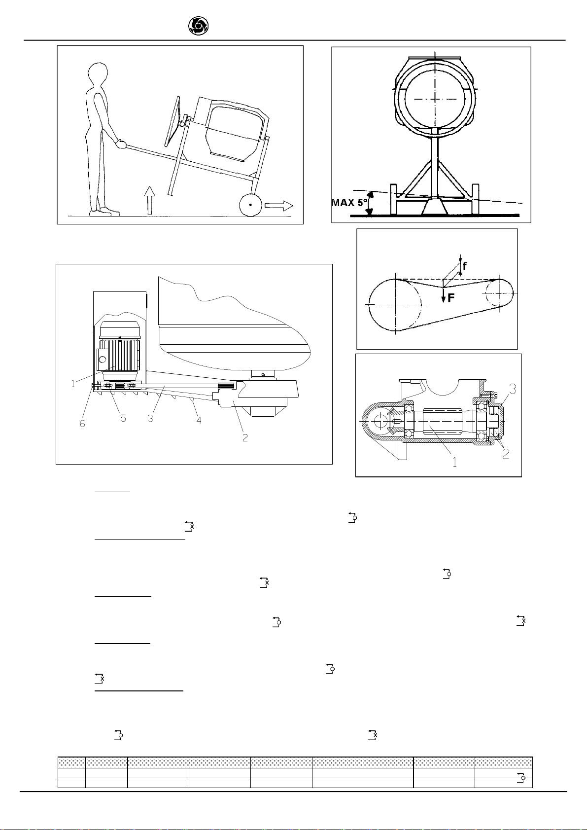
19
IMERINTERNATIONALS.p.A.
S190-S250 -S300-S350 EL
RICAMBI: Pertuttigli ordini deipezzidi ricambiovogliateindicare:1-Tipodi macchina.2-Numerodi codiceedi riferimento
collocatoincorrispondenzadi ogni definizione.3-Numerodiserieeanno di costruzioneriportatosullatarghettadella macchina.
SIMBOLOGIA:Intercambiabilità(esempio):FinoallamacchinamatricolaN°5240 èstatoinstallatoilrif.1cod.3204530,dallamacchina
matricolaN° 5241 èstatoinstallatoil rif.1.1cod.3204520.Ilrif.1.1èintercambiabile()conil rif.1. Nonsonointercambiabili irif.1erif.1.1
sein tabellaèpresenteil simbolo().
PIECES DERECHANGE: Pourtouteslescommandesdepiècesderechange,veuillezindiquer:1-LeTypedemachine2-Le
Numérodecodeetderéférencesetrouvantenfacedechaquedéfinition3-LeNumérodesérieetl'année deconstructionsetrouvant
surlaplaquetted'identificationdelamachine
SYMBOLOGIE:interchangeabilité(exemple):Jusqu'àlamachinematriculeN°5240,nousavonsinstallélaréf.1code3204530;àpartirde
lamachinematriculeN°5241,nousavonsinstallélaréf.1.1code3204520.Laréf.1.1estinterchangeable()aveclaréf.1.Lesréf.
1etréf.1.1nesontpasinterchangeblessilesymbole()n'estpassurletableau.
SPAREPARTS: All ordersforsparepartsmustindicatethefollowing:1-Typeofmachine.2-Partnumberand positionnumber
ofeachpart.3-Serialnumberand yearofmanufacturereportedonthemachine'sidentificationplate.
SYMBOL:Interchangeability(example):Pos..1P.n.3204530 wasinstalledonmachincs up toN°5240 and Pos.1.1P.n.3204520 installed
onmachineN°5241 onwards.Pos.1.1isinterchangeable()withPos.1.Pos.1and Pos.1.1arenotinterchangeableifthe()
symbolappearsinthe table.
ERSATZTEILE: FürErsatzteilbestellungenbittediefolgendenAngabenmachen:1)Maschinentyp2)JeweilszugeordneteArt.-
Nr.undPositionsnummer3)SeriennummerundBaujahr(AngabeaufdemMaschinenschild)
SYMBOLE:Austauschbarkeit(Beispiel):BiszurMaschinenummer5240 istRef.1Cod.3204530 und abMaschinennummer5241 istRef.
1.1Cod.3204520 installiertworden.Ref.1.1und Ref.1sind austaschbar().Ref.1und Ref.1.1sind nichtaustauschbar,wenn das
Symbol()angegebenist.
PIEZASDERECAMBIO: Parapedirunapiezaderecambiohayqueindicarsiempre:1-Eltipodemáquina.2-Losnúmerosde
gódigoydereferencia indicadosencorrespondencia decadadefinición.3-Elnúmerodeserieyelañodeconstrucciónindicadosen
laplacadelamáquina.
SIMBOLOGIA:Intercambiabilidad(ejemplo):HastaelequipoconmatrìculaN°5240,sehainstaladolapiezaconref.1ycòd.3204530;
apartirde lamàquinacon matrìculaN°5241,seha instaladolapiezaconref. 1.1ycòd.3204520.Lapiezaconref. 1.1sepuede
intercambiar()conlapiezaconref.1.Sientablasehallapresenteelsìmbolo(),laspiezascoreferencia1y1.1noson
intercabiables.
Rif. Cod. I F GB D E Note
13204530 Riduttore Réducteur Reducer Untersetzungsgetriebe Reductor 5240
2 3204520 Riduttore Réducteur Reducer Untersetzungsgetriebe Reductor 5241
Fig. 4
Fig. 5
Fig. 7
Fig. 8
Fig. 6
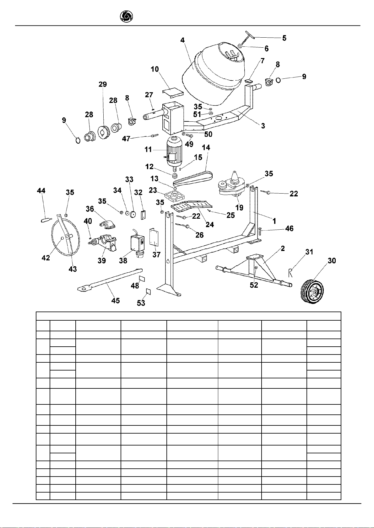
20
IMERINTERNATIONALS.p.A.
S190-S250 -S300-S350 EL
TAV.1-BETONIERA-BETONNIERE-CONCRETEMIXER-BETONMISCHER-HORMIGONERA:S190(1105650)S250 (1105700-1105703)
RIF. COD. DESCRIZIONE DESCRIPTION DESCRIPTION BESCHREIBUNG DESCRIPCION NOTE
13208817 TELAIO CHâSSIS FRAME RAHMEN BASTIDOR
23208819 ASSALERUOTE ESSIEUROUES WHEELAXLE RADACHSE EJERUEDAS S190
3208685 S250
3 3208782 BRACCIO BRAS ARM ARM BRAZO
43208830 VASCA CUVE MALAXAGE DRUMASS'Y TROG TAMBORDEMEZCLA S190
3208811 S250
5 3206690 LEVA BLOCCAGGIO
VASCA LEVIERBLOC.CUVETANKLOCKLEVER SPERRHEBEL
BECKEN PALANCABLOQUEO
CUBA
63207225 RONDELLA
BLOCCAGGIO
VASCA
RONDELLE
BLOC.CUVE TANKLOCKWASHER SPERRSCHEIBE
BECKEN ARANDELA
BLOQUEO CUBA
73208806 TAPPO BOUCHON
D'EXTRÉMITÉ PLUG VERSCHLUßSTOPF-
EN TAPÓNTERMINAL
83208792 BLOCCHETTO
SUPP.BRACCIO BLOC.SUPP.BRAS ARMSUPPORTBLOCKARMLAGERBLOCK BLOQUEO SOP.
BRAZO
92227205 ANELLO ARRESTO BAGUED'ARRET STOPRING SPERRING ANILLO DETOPE E 50
10 3208787 CHIUSURABRACCIO FERMETUREDU
BRAS ARMCLOSURE ARMVERSCHLUSS CIERREDELBRAZO
11 3208824 MOTOREELETTRICO MOTEUR
MONOPHASE SINGLE-PHASE MOTOR EINPHASENSTROM-
MOTER MOTOR
MONOFASICO 1KW-230V/50HZ
3210698 1KW-110V/50HZ
12 3208828 PULEGGIA POULIE PULLEY RIEMENSCHEIBE POLEA
13 2227214 ANELLO ARRESTO BAGUED'ARRET STOPRING SPERRING ANILLO DETOPE E 14
14 3208791 CINGHIA COURROIE BELT RIEMEN CORREA 340 J6
15 *LINGUETTA LANGUETTE KEY KEIL LENGUETA 5X5X16
19 3208746 RIDUTTORE REDUCTEUR GEARBOX GETRIEBE REDUCTOR TAV. 3
This manual suits for next models
13
Table of contents
Languages:
Other IMER Construction Equipment manuals


