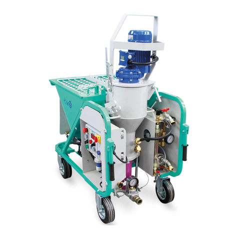
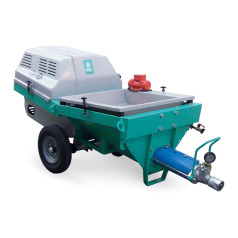
IMER KOINE 3 Guide

M RTAR MIXER
perating,maintenance,spare parts manual
OINE 3
(1106007-1106008-1106009)

DECLARATIE DE CONFORMITATE ДЕКЛАРАЦИЯ ЗА СЪОТВЕТСТВИЕ
DECLARATION OF CONFORMITY DECLARACION DE CONFORMIDAD
DICHIARAZIONE DI CONFORMITÀ
MEGFELELŐSÉGI NYILATKOZAT
Adresa: - Address: - Indirizzo: - Aдрес: - Direcciòn: - Cím:
Loc. Salceto, 53-55 - (53036) Poggibonsi - Siena -Italia
KOINE 3
230V/50Hz - kW 3.4
Masina de tencuit
Mortar mixer
Intonacatrice
Машина за мазилк
Enfoscadora
HabarcskeverŐ
Seria / Nr
Serial number
Matricola N°
Сериен номер
Numero de serie
Sorozatszám
In conformitate cu toate conditiile cerute de
2014/30/CE
2014/35/CE
2006/42/CE - II
2000/14/CE - A/II
Complies with the provisions of the Directive
E' conforme ai requisiti delle Directive
В съответствие с разпоредбите на директивата
Corresponde a las exigencias bàsicas de le directive
Rendelkezéseinek megfelel az irányelv
Totodata sunt aplicate urmatoarele norme armonizate
The following national technical standards and specifications have been used
Inoltre dichiara che sono state applicate le segueti altre direttive
EN ISO 12100
EN 60204-1
EN 12001
EN ISO 3744
Следните национални технически стандарти и спецификации са били използвани
Ademàs declaratamos que las siguientes normas armonizades fueron aplicadas
Az alábbi nemzeti szabványok és előírások figyelembevételével
Semneaza - Signs - Segni - знак - Signos - Aláírás
Ing. Loris Pagotto
IMER International SpA
Emis la - Emitted at - Rilasciato - изпускани в - Emitido - Emittált GS
Pogibonsi SI
This document is a translation from English of the CE certificate issued by the manufacturer, which is found in the
user manual of equipment.
Questo documento è una traduzione dall'inglese del certificato CE rilasciato dal productore, che si trova nel
manuale utente delle macchine.
Този документ е превод от английски на сертификата за CE, издаден от производителя, който се намира в
инструкцията за употреба на оборудване.
Este documento es una traducción del Inglés del certificado CE expedido por el fabricante, que se encuentra en el
manual del usuario del equipo.
Jelen dokumentum az angol CE igazolás alapján készült, melyet a gyártó állított ki, és amely a készülék
felhasználói kezikönyvében szerepel
Producator si titularul fisei tehnice: - Manufacturer and holder of the technical file: - Fabbricante e detentore del fascicolo tecnico: - производител и
притежател на техническото досие: - Fabricante y el titular del expediente técnico: - A múszaki dokumentáció gyártója és birtokosa
IMER International S.p.A
Prin prezenta declaram ca echipamentul - Herewith we declare that the machine - Dichiara che il
prodotto - С настоящото декларираме, че машината - Declaramos que el producto - Ezennel
kijelentjük, hogy a gép
Acest document reprezinta traducerea din limba engleza a a certificatului CE emis de producator, care se gaseste
in manualul de utilizare al echipamentului
Max. LWA = 87 dB (A)
Min. LWA = 90 dB (A)

2
IMER INTERNATIONAL S.p.A.
K INE 3
Special attention must be given to warnings with this symbol:
FIG. 1
ENGLISH
1-WHEELED FRAME
2-H PPER UNIT
3-M T R UNIT
4-GRID
5-MATERIAL UTFEED UNIT
6-WATER CIRCUIT
7-SELF-PRIMING PUMP
8-ELECTRICAL PANEL
9-C MPRESS R IM250
10-AIR UNIT
11-SCRAPER
5
2
4
16
9
7
11
8
10

3
IMER INTERNATIONAL S.p.A.
K INE 3
- TA B L E -
G B K O IN E
K O IN E L
T E C H N IC A L D AT A
M a c hine cod e
K OIN E
11 0 6 0 0 7
11 0 6 0 0 9
K O IN E L 11 0 6 0 0 8
M A IN P W E R S UP P LY V
H z
2 2 0 -2 3 0
5 0 -6 0
C N TR LS P W E R S UP P LY V 2 4
E L E C T R IC A L C N N E C T I N
C N N E C T R
(M N -P HA S E )
F U S E S
C A B LE ( U P T 20 M )
V
A
m m
2 3 0
1 6
2 .5 x3
G E NE R A T R S E T
(M INIM U M ) kV A 1 2
W A T E R C N N E C T I N 3 /4 "
G E A R M T R
M IX E R
kW
A
r.p .m .
2 .2
9 .9
3 2 0
W A T E R P U MP kW
A
0 .4 5
3 .3
C M P R E S S R IM 2 50 kW
A
N l/m in
0 .7 5
5 .6
2 5 0
M A X IM U M P W E R k W 3 .4
W A T E R P R E S S U R E S W ITC H
S E TT ING (M IN /M A X ) b a r 1 .9 /2 .1
P R E S S UR E S TA B ILIS E R
S E TT ING b a r 1 .9
M IX E R G E A R M T R
P R E S S UR E S W ITC H
S E TT ING (M IN/M A X )
b a r 0 .9 /1 .2
C M P R E S S R P R E S S UR E
S W ITC H S E TTIN G ( M IN/M A X ) b a r 1 .8 /2 .8
C M P R E S S R S A F E TY V A LV E
S E TT ING b a r 4
M A T E RIA L F L W R A TE W ITH
P U M P E C O -S TA R
(K O IN E )
l/m in
8
11
1 5
M A T E RIA L F L W R A TE W ITH
P U M P D 8 1 .5
(K O IN E L )
l/m in
1 2
1 6
2 0
M A X IM UM P R E S S U R E b a r 2 0
M A X IM UM P U M P ING
D IS TA NC E (*)
H S E D IA M . 2 5 M M
H S E D IA M .3 5 M M
m
m
1 5
3 0
D IM E N S I N S
X
Y
Z
m m
m m
m m
1 4 5 0
6 8 5
1 2 7 0
L A D IN G H E IG H T m m 1 0 0 0
H P P E R C A P A C ITY
K O IN E
-K O IN E L l-5 0
-7 0
W E IG H T
P U M P G E A R M T R
M IX ING C HA M B E R
M A C HIN E B D Y
C M P RE S S R
T TA L
k g 1 9 1
N IS E E M IS S I N
L E V E L
LP A a 1 m -
LW A -
E N IS 3 7 4 4
(2 0 0 0 /1 4 /E C )
d B (A )
< 7 6
9 0
D E S IG N S TA N D A RD S
E N IS 1 2 1 0 0 - 1 /2
E N 6 0 2 0 4 -1
E N 1 2 0 0 1
,
+
~
(*) N O T E : T H E P U M P IN G D IS TA N C E IS S U B J E C T T O VA R IAT IO N S , W H IC H M AY R E G A R D : T H E T YP E O F M AT E R IA L U S E D , S E R V IC E H E IG H T, C O N S IS T E N C Y O F M AT E R IA L , T YP E O F P U M P (S C R E W
S TAT O R ) IN S TA L L E D .
O

4
IMER INTERNATIONAL S.p.A.
K INE 3
The water flow rate is regulated by means of a micrometric
valve and displayed via a flow meter (see exploded drawing
WATER CIRCUIT page18).
The mixer drives a helical rotor pump which conveys the material
via a rubber hose to the spray jet. The spray jet is connected
both to the material hose and an air hose. The air is delivered by
the compressor to the spray jet for application on the parts to be
plastered.
5. OPERATION SAFETY
- Before using the plastering machine, ensure that it
is fitted with all safety devices.
- Never insert parts of the body and/or tools in the
hopper or mixing chamber during operation.
All current standards governing accident prevention and safety
devices must be observed in the workplace.
Take care when handling sacks of material to avoid dispersion
of dust with inhalation of the latter; if this is not possible, masks
must be worn to protect the mouth and nose.
- Never use the machine in environments subject to
the risk of explosions, fire or underground.
The mortar mixer is not equipped with a lighting system and
therefore the workplace must be fitted with adequate lighting.
The power lines must be laid to prevent any possible damage.
Never place the plastering machine on electric power cables.
Ensure that the electrical connection is protected against the risk
of water penetration in connectors. Use exclusively connectors
and couplings equipped with water spray protection.
- Never use inadequate or provisional electric lines: if in doubt
consult specialist personnel for assistance.
- Repairs to the electrical circuit must be performed exclusively
by specialised personnel. Disconnect the machine from the power
supply before performing maintenance or repairs.
-
Avoid contact of electric wires with movable and/or moving
parts of the machine to avoid injury from contact with live metal
parts.
6. ELECTRICAL SAFETY
The plastering machine
Koine 3 is constructed according to
standard EN 60204-1, with protection against water sprays and
protection against overload and power failure.
The plastering machine
must be connected to the earthing circuit.
Dear Customer,
compliments on your purchase: this IMER plastering machine,
the result of long-standing experience in the field, features
maximum reliability and innovative technical solutions.
- WOR ING IN SAFETY..
To ensure complete safety, read all the instructions in
this manual carefully.
This PERATI N AND MAINTENANCE manual must be kept by
the Site Manager and be always available for consultation.
The manual is considered part of the machine and must be stored
for future reference ( EN IS 12100-2 ) through to scrapping of
the machine itself. If the manual is lost or damaged, a replacement
copy can be ordered from the manufacturer.
The manual contains the EC declaration of conformity (2006-42/
EC) important information on construction site procedures,
installation, operation, maintenance and requests for spare parts.
Nevertheless, the user must both have adequate experience
and knowledge of the machine prior to use: the user should be
trained by a person totally familiar with the operation and use of
this machine.
To guarantee complete safety of the operator, safe operation
and long life of equipment, follow the instructions in this manual
carefully, and observe all safety standards currently in force for
the prevention of accidents at work (use of safety footwear
and suitable clothing, helmets, gloves, goggles etc.).
- Make sure that all signs are legible.
- Never make any modifications to the metal structure
or plastering machine systems.
IMER INTERNATI NAL accepts no responsibility in the event of
failure to comply with laws governing the use of this type of
equipment, with particular reference to: improper use, incorrect
power supply, lack of maintenance, unauthorised modifications,
failure to comply, either wholly or partially, with the instructions
set out in this manual.
IMER INTERNATI NAL reserves the right to modify the
characteristics of the plastering machine and/or contents of this
manual, without the obligation to update the previous machine
and/or manuals.
1. TECHNICAL DATA
Table 1 provides the technical specifications of the plastering
machine, with reference to figure 1.
2. DESIGN STANDARDS
The plastering machines have been designed and constructed
according to the standards specified in table 1.
3. NOISE EMISSION LEVEL
Table 1 shows the sound pressure levels of the plastering
machine measured at the ear of the operator (L
pA
at 1 m) and
noise emission levels in the environment (power L
WA
) measured
according to EN IS 3744 (2000/14/CE).
4. DESCRIPTION OF PLASTERING MACHINE
OPERATION
- The plastering machine is designed for use in
building sites, for mixing and pumping all mixed mortars
declared as compatible with this type of machine by the
material manufacturers: gypsum based plasters,
anhydrite based plasters, lime/cement based plasters,
external insulating mortar, grouting mortar etc
4.1 PLASTERING MACHINE DESCRIPTION (Fig. 1)
The plastering machine comprises a wheeled frame (ref.1), which
supports a hopper (ref.2), complete with a motor unit (ref. 3), a
grid (ref. 4) and a material outfeed unit (ref.5). a water circuit
(ref.6) complete with self-priming pump (ref.7); an electrical panel
(ref.8); a diaphragm compressor (ref.9) complete with air unit
(ref.10); a scraper with rod (ref.11) and a mixer inside the hopper
(see exploded drawing K INE 3).
The pre-mixed dry material is poured in to the hopper,
in which the mixer moves the material by means of a gearmotor.
The material is mixed with the water delivered by the water
circuit, which in turn receives water from the mains supply or a
specific container.
ORIGINALINSTRUCTIONS

5
IMER INTERNATIONAL S.p.A.
K INE 3
- CAUTION! Lift with care to avoid hazardous
oscillations
- CAUTION! Never use points other than as specified
in figure 3 to lift the machine and in particular do not
hook up lifting equipment to the gearmotor guard.
Use lifting equipment suited to the overall weight of the machine
indicated in table 1.
To facilitate transport, the machine can be disassembled into the
motor unit, hopper unit and compressor.
9. INSTALLATION
Position the plastering machine on a flat surface in an area
where it does not constitute an obstruction either during use or
cleaning at the end of the work shift and where a minimum
quantity of pipelines is required.
Secure the machine in place by means of the wheel brake.
10. CONNECTIONS
10.1 ELECTRICAL CONNECTION
- Ensure that the power supply voltage, mains
frequency and electrical connection (socket, fuses, cable)
correspond to specifications in table 1.
The power supply line must be equipped with current overload
protection (e.g. with fuses or a thermal cut-out) and protection
against current dispersion to ground (e.g. residual current circuit
breaker). The electric cable wire size must take into account the
operating currents and length of the line to avoid excessive
voltage drops.
Avoid use of extension leads wound on drums. The power
cable must be suitable for frequent movements and with an
abrasion resistant sheath (e.g. type H07RN-F).
Before connecting the plastering machine to the electrical mains,
ensure that all safety devices are fitted and are in perfect
condition, and check in particular that the hopper grid is secured
in place, that the extension in good condition and that the plugs
and sockets are not wet.
Connect the plastering machine plug on the electrical panel to the
mains; the blue indicator light turns on to indicate power N
(ref.2). If the blue light remains off, the voltage exceeds 240V.
7. MECHANICAL SAFETY
The hazardous points on the IMER plastering machine are pro-
tected by means of suitable safety devices, which must remain
fitted at all times and kept in perfect condition, such as the elec-
tric motor cooling fan guard, the grid on the hopper to prevent
contact with the mixer
In particular, the opening of the motor support flange or removal
of the hopper grid causes shutdown of the rotary parts of the
machine thanks to a specific safety microswitch.
8. TRANSPORT
- CAUTION! Before moving the plastering machine,
always detach the power plug.
Before moving the plastering machine the water delivery hose
and material delivery line must be detached.
nly a minimal amount of the material should be in the hopper
when handling.
Release the wheel by means of the brake and move the mixer by
means of the handles (as shown in the figure below)
- CAUTION! Before lifting the plastering machine,
always disassemble the compressor for separate transport.
- CAUTION! Before lifting the plastering machine,
always check that all machine components are correctly
secured and fitted in place.
To lift the machine, use the two specific attachment rings on the
sides of the machine (as shown in the figure below)
RH LATERAL
RING
BRAKE

6
IMER INTERNATIONAL S.p.A.
K INE 3
10.2 WATER CONNECTION
Connect the water hose (table 1) from the pump to the water
mains.
The water mains must guarantee a minimum flow rate of
15l/min.
therwise a tank of suitable capacity (200 l) must be fitted with
clean water, to be kept full at all times, and from which water can
be taken by means of the self-priming pump supplied with the
machine. In this case the hose must have a minimum diameter of
3/4", a maximum length of 3m, preferably a foot filter and must
not be subject to deformation during use. Ensure that pressure
is sufficient. Turn the main switch to 1; the green light on the
panel illuminates (ref.8)
- CAUTION! The first time the water pump is connected
to the tank, it must be activated by manually filling the
intake line.
The same operation must be repeated each time the
circuit is drained, or after a prolonged period of disuse.
10.3 AIR CONNECTION
Connect the air hose to the machine panel and spray jet as
shown in the figure below.
pen the spray jet air valve.
FIG.7
10.3 CORRECT CONNECTIONS FOR MATERIAL LINES
Take the material hoses and check that they are in perfect
condition, that the couplings are intact and all relative seals are
present. Check that the cam levers ( A ) of the couplings have
been tightened correctly and that the seal (B) is fitted as shown
in the figure below.
( A )
( B )
11. START-UP
Before starting up the machine, check that the air valve on the
spray jet is open (ref.11).
Turn the main switch (ref.1) on the electrical panel to 1; the
compressor is activated. Using the two pushbuttons (ref.3),
access start command n°2(ref.4) on the display.
Remove the water level cap (ref.12), positioned a the side on the
lower section of the hopper unit and ensure that there is no
material obstructing the hole. If clogged, clean by means of the
longer section of the water level cap.
Press the water supplement button (ref.9) and check that the
water comes out of the relative hole of the water level cap. Use
the micrometric valve (ref.13) to set the water flow rate, as
displayed by the flow meter (ref.14) respectively
-at 300 l/min for cement-based products
-at 500 l/min for gypsum based products
Refit the water level cap in its hole and close securely.
Load the hopper with the relative premixed material in sacks.
Position the start selector (ref.5) to N (rotate to the right), to
start up the machine.
Wait for material to be delivered from the jet and at the same time
load the material hopper.
At this point the mix delivered by the jet can be adjusted by
correcting the quantity of water as required.
Use the micrometric valve, reducing the flow rate by 20l at a
time, to obtain the required consistency.
When the jet starts to deliver material at the required consistency,
normal work can be started.
The machine starts and stops by opening and closing the air
supply to the spray jet.
The machine is fitted with protection against power failure or
surges (see paragraph Errors, page 8): if one of these events
occurs, the thermal cut-out trips. In this case reset the switch
(ref.5) and turn the main switch to 1.
In the event of water pressure failure (see table
Troubleshooting,
page 10), the motor shuts down and the green light turns off
(ref.8). The machine restarts automatically when sufficient
pressure is restored.
To stop the machine in the event of an emergency, press the red
emergency button (ref.10) - all moving parts are shut down -
then turn the main switch to 0 and remove the electric power
plug from the mains socket.

7
IMER INTERNATIONAL S.p.A.
K INE 3
11
1
12
14
1
5
4
6
10
2
8
7
9

8
IMER INTERNATIONAL S.p.A.
K INE 3
THERMAL CUT-OUT PROTECTION:
- The water pump and compressor are protected by a
thermal cut-out inside the pressure switches connected
to the inverter panel. As well as the panel thermal cut-
out, the mixer motor also implements a number of safety
levels, as indicated on the display.
ERROR MESSAGES (SHOWN ON PANEL DISPLAY):
- The error messages are shown on the inverter panel
display when specific situations arise:
-
ERR00
: Phase dispersion of current surge on inverter module
-
ERR01
: Thermal cut-out on dissipater
-
ERR02
: Motor thermal cut-out
-
ERR0
: Not used
-
ERR04
: Motor temperature too high (on the basis of motor heat
dissipation)
-
ERR05
: Power supply voltage too low.
Note: Refer to the table
Troubleshooting
on page 10, for further
information.
12. OPERATION
-
The hopper safety grid must be fitted and secured
at all times.
Never place materials other than premixed dry materials
in the hopper.
-
Removal of the hopper grid causes shutdown of the
machine moving parts.
If this occurs, the grid must be refitted and the main
switch must be reset to O to enable machine restart .
- Wear envisaged personal protection devices before
starting work
Different diameters of deflector are available (10,12,14,16,18 mm):
the smaller deflectors enable improved nebulisation, and the
larger ones are more suited to materials with a larger particle
size.
For standard plastering materials the deflector with 14 mm hole
is used.
However, it is important to measure the distance of the nozzle
from the outlet so that it is the same as the diameter of the
deflector.
If no water is delivered, the machine shuts down.
Before restarting the machine, identify the cause of the problem:
valve closed, delivery hose bent, tank empty, clogged filter.
Interruptions exceeding 30min should be avoided.
Prolonged shutdown can cause clogging in the material delivery
lines: in this case no material is delivered from the jet and the
pressure gauge indicates a higher pressure than the normal
working value.
Shut down the machine by setting the main switch to 0.
Locate the point of clogging in the hose
and remove by tapping the pipeline with a mallet.
- If necessary, disconnect the jet or open the pipeline
couplings, checking previously if any residual pressure
is present.
The material pressure gauge must indicate 0 bar and the
pipelines, excluding the clogged sections, must be flexible.
The personnel assigned for this task must be specially
trained in these procedures.
In the event of any doubt as to the presence of residual
pressure, never open the couplings.
Reconnect the pipelines and spray jet, set the main switch to the
correct position (the blue lamp illuminates) and restart the
machine.
- Do not move the machine with the hopper full.
If the material delivered is alternately hard and soft this may
indicate a worn pump. To replace the pump, proceed as follows:
release the handle on the left of the hopper unit. Insert the tube
wrench on the end of the mixer and unscrew until the screw
inside the stator is released. Close the mixing chamber, tilt and
lock in the lifted position, remove the material delivery manifold
and fit a new screw-stator unit.
To insert the screw in the stator, use the lubricant spray available
from IMER. Never use mineral oil or grease for screw assembly
as this may damage the stator. Avoid all types of benzene.
In the case of a power failure during operation
promptly wash
the machine and pipes. Also disassemble the pump, remove the
screw from the stator and clean. n completion reassemble all
components.
13. MACHINE SHUTDOWN AND CLEANING
At the end of work, continue pumping until the hopper and material
delivery pipelines are empty.
Stop the machine and set the main switch to 0.
pen the jet valve, detach the jet and clean thoroughly, cleaning
the nozzle with the special tool supplied (as shown below).
- Before disconnecting the jet or pipelines, ensure
that there is no residual pressure.
Disconnect the material pipelines from the delivery manifold.
Detach the quick connector with safety device and open the
mixing chamber of the hopper unit.
Remove the mixer and clean. Clean the mixing zone with a brush.
Insert the scraper, connecting it to the coupling with the gearmotor,
Stop the machine and remove the scraper; refit the clean mixer.
Proceed with pipeline cleaning.
Insert a washing sponge (see spray jet kit) at the start of the
pipeline, connect the material delivery hose to the mortar hose-
water hose coupling, and then connect the latter to the auxiliary
water valve. Insert the water pump and open the auxiliary water
valve until the washing sponge comes out from the other end.
Repeat the operation until the pipeline is perfectly clean.
At this point, on completion of machine cleaning, turn off the main
switch, disconnect the power plug, close the water delivery
valve, open the auxiliary valve for a few seconds and detach
the delivery hose
If there is any risk of freezing, open the four valves on the water
circuit and drain all water from the circuit.
Remember to reclose the valves before restarting the machine.

9
IMER INTERNATIONAL S.p.A.
K INE 3
14. MAINTENANCE
- Maintenance must be performed by adequately
trained personnel, after switching off the machine,
disconnecting it from the power supply and emptying the
hopper.
Check daily that the water filter is clean.
Check weekly that the compressor air filter is clean. If
deteriorated, replace.
Check weekly that the mixer is in good condition and replace if
necessary.
Check weekly that the motor connection is in good condition and
replace if necessary.
Check weekly that the electric motors are free of dust and dirt
and if necessary clean using compressed air.
Check weekly that the plug and socket contacts are clean, dry
and rust free.
Every six months arrange for an inspection of the machine by an
authorised IMER service centre.
-
Spent oil is a special waste. Therefore it must be
disposed of according to current legislation.
-
Always keep notices and symbols on the machine
legible
15. REPAIRS
- Never start up the plastering machine during
repairs.
Repairs to the electrical installation must be performed exclusively
by specialised personnel.
Use exclusively original IMER spare parts; modifications
to parts are strictly prohibited.
- If any guards are removed for repairs, ensure they
are refitted correctly at the end of work.

10
IMER INTERNATIONAL S.p.A.
!"#$%&'
INCONVENIENTI CAUSE RIMEDI
La macchina non parte Acqua
h/3*)&4)*++2)*&3--&7-i6&3F*&L/2L*&+F-i+&4)*++2)*&5*7-i&;&5/)&<L)**.
7/84&-.?@A&3F*&9,+47/B&+F-i+&3F*&3*c3&C;"
D&EF*0j&3F/3&i/3*)&,+&9*7,=*)*9&:)-8&3F*&+2447B&F-+*
D&EF*0j&3F/3&3F*&i/3*)&:,73*)&,+&07*/.
D&EF*0j&3F/3&3F*&i/3*)&4284&,+&+i,30F*9&-.
D&#:&3F*&4284&0-77*03+&:)-8&/&3/.jA&0F*0j&3F/3&,3&F/+&5**.&4),8*9&/.9&3F*)*&/)*
&&.-&7*/j+&:)-8&0-247,.L+
Machine does not start Material
-&()-9203&3--&9)B&,.&8,c,.L&0F/85*)
&<8-)3/)&4284&+*,H*9?&)*9&7/84&-.?@
D&#.,3,/7&+3/)3D24&.-3&4*):-)8*9&0-))*037B&<+**&4/)/JKK@
D&h/3*)&:7-i&)/3*&+*33,.L&3--&7-i&<+**&4/)/JKK@
D&$-&i/3*)&9*7,=*)*9&3-&8,c,.L&0F/85*)
&&<i/3*)&,.7*3&-5+3)203*9A&i/3*)&+-7*.-,9&=/7=*&8/7:2.03,-.@
Machine does not start Air
-&PF*&/,)&4)*++2)*A&i,3F&g*3&=/7=*&0-847*3*7B&-4*.A&9-*+&.-3&:/77&5*7-i&3F*
8,.,828&4)*++2)*&=/72*&-.&3F*&8/0F,.*&4)*++2)*&+i,30F&<3/57*&K@
D&EF*0j&3F/3&3F*&/,)&F-+*&,+&.-3&5*.3&-)&-5+3)203*9-
D&EF*0j&3F/3&3F*&g*3&.-HH7*&,+&4*):*037B&07*/.
Machine does not start Grid
-&N),9&.-3&,.+*)3*9&0-847*3*7B`&3F*&9,+47/B&+F-i+&3F*&3*c3&O7-0
D&&EF*0j&3F/3&3F*&L),9&,+&4-+,3,-.*9&0-))*037B
Machine does not start
and compressor does not
start and the blue light is
OFF
Electrical current
-$-&02))*.3&9*7,=*)*9&3-&0-..*03-)&-:&+,3*&4/.*7
&<:2+*+?@
D&$-&4-i*)&9*7,=*)*9&3-&8/0F,.*
<9*:*03,=*&0-..*03-)&0-..*03,-.?&7--+*&0/57*?@
D&W/,.&+i,30F&.-3&"$
D&EF*0j&4-,.3+&7,+3*9&/7-.L+,9*
Machine does not start but
compressor starts
Electrical current
D&I3/)3&42+F5233-.&.-3&4)*++*9
D&M-i&i/3*)&4)*++2)*&+i,30F&3),4+&-.&+3/)3D24
<i/3*)&4284&+i,30F*9&-.&?see also "machine does not start due to
water)
D&EF*0j&4-,.3+&7,+3*9&/7-.L+,9*
Machine does not stop
and/or compressor does
not stop
Air
-&T,)&F-+*&9*:*03,=*
&&<F-+*&023?&T,)&7*/j+&:)-8&0-247,.L+?
D&E-84)*++-)&/,)&+2447B&7-i
D&k*3&/,)&=/7=*&:/273B&<57-0j*9&,.&-4*.&4-+,3,-.@
D&EF*0j&3F*&/,)&F-+*&/.9&0-247,.L+&,.&4/)3,027/)&/.9&)*47/0*&,:&.*0*++/)B
D&EF*0j&/,)&:,73*)&<+**&4/)/J&K;@
D&EF*0j&0-84)*++-)&)*7,*:&=/7=*
Machine stops after
starting up
Water
-&#.3/j*&:,73*)&07-LL*9
D&()*++2)*&)*920*)&:,73*)&07-LL*9
-&h/3*)&F-+*&3--&7-.L&/.9S-)&3--&./))-i
D&h/3*)&+2447B&,.+2::,0,*.3
D&EF*0j&4-,.3+&7,+3*9&/7-.L+,9*6&07*/.&:,73*)+A&0F*0j&:-)&/9*12/3*&:7-i&)/3*&:)-8&3F*
i/3*)&F-+*&</3&7*/+3&KUDK;&7S8,.&,:&i-)j,.L&i,3F&7,8*D0*8*.3&5/+*9&47/+3*)A&/3&7*/+3
KVD;U&7S8,.&i,3F&LB4+28&5/+*9&47/+3*)+@&/.9&)*47/0*&F-+*&,:&.*0*++/)B&-)&0-77*03
i/3*)&:)-8&/.&/2c,7,/)B&3/.j
The machine stops during
operation
The following texts appear
on display
- ERR00 :&C-44*)&L),77*&-4*.&-)&,.0-))*037B&7-0/3*9J
D&I0)*i&4284&8-3-)&3F*)8/7&023-23&<+**&%))U;@J
D&%8*)L*.0B&5233-.&4)*++*9J
D&IB+3*8&8/7:2.03,-.J
D&%.+2)*&3F*&L),77*&,+&4)-4*)7B&7-0/3*9
D&h/,3&:-)&,3&0--7&9-i.A&3F*.&)*+3/)3J
D&Q*+*3&3F*&*8*)L*.0B&5233-.J
D&E-.3/03&T++,+3/.0*&I*)=,0*
- ERR01 : C,LF&0,)02,3&5-/)9&3*84*)/32)*&<#.=*)3*)@J D&h/,3&:-)&,3&0--7&9-i.A&3F*.&)*+3/)3J
- ERR02 : C,LF&+0)*i&4284&8-3-)&3*84*)/32)*J
D&PF*&8-3-)&F/+&5**.&+25g*03*9&3-&-=*)7-/9,.L&:-)&/&7-.L&3,8*J
D&h/,3&:-)&,3&0--7&9-i.A&3F*.&)*+3/)3J
D&E-))*03&3F*&8,c32)*&,.&2+*J
- ERR0 : P--&820F&4-i*)&)*12,)*9&:)-8&+0)*i&4284&8-3-)&<8-3-)
g/88*9@J
D&T99&i/3*)&3-&8,c32)*J
D&T99&5,.9*)&3-&8,c32)*J
D&Y+*&+/.9&i,3F&-43,8,H*9&4/)3,07*&+,H*&02)=*J
D&Q*8-=*&57-0j/L*J
- ERR04 : I0)*i&4284&8-3-)&-=*)7-/9&i/).,.LJ D&Y+*&+/.9&i,3F&-43,8,H*9&4/)3,07*&+,H*&02)=*J
D&T99&i/3*)&3-&8,c32)*J
D&T99&5,.9*)&3-&8,c32)*J
D&Q*920*&+0)*i&4284&8-3-)&+4**9J
D%.+2)*&3F/3&3F*&4-i*)&=-73/L*&,+&,.&3F*&)/.L*&;UUX&3-&;'UX&iF*.&3F*&8/0F,.*&,+
-4*)/3,.LA&3F/3&3F*&4-i*)&0/57*+&/)*&4)-4*)7B&)/3*9&/.9&3F/3&.-&-3F*)&*12,48*.3
<0)/.*+A&7,:3+A&+/i+A&0-.0)*3*&8,c*)+A&*30J@&,+&0-..*03*9&3-&3F*&+/8*&+2447BJ
- ERR05 : PF*&0-84)*++-)&32).+&-.&/.9&-::&3--&:)*12*.37B&/73F-2LF&3F*&/,)
3/4&423&-.&3F*&+4)/B&g*3&,+&07-+*9
DT,)&F-+*&42.032)*9J
DM*/j/L*&:)-8&2.,-.+J
DQ*47/0*&3F*&L/+j*3+
DI*/7&3F*&0-247,.L+
DQ*47/0*&3F*&/,)&3/4&-:&3F*&+4)/B&g*3
- ERR06 : #.+3/.3/.*-2+&4-i*)&=-73/L*&-=*)&;ZVXJ D&EF*0j&3F*&12/7,3B&-:&3F*&02))*.3&9*7,=*)*9&5B&3F*&4-i*)&+2447B&<12/7,:,*9
*7*03),0,/.@J
- ERR07 : E2))*.3&7-++&3-&L)-2.9&-)&+B+3*8&8/7:2.03,-.J E-.3/03&T++,+3/.0*&I*)=,0*J
EF*0j&:-)&i/3*)&,.&+B+3*8J
- ERR 08 : (-i*)&=-73/L*&3--&7-i6
D&M-i*)&3F/.&K]UX
%.+2)*&3F/3&3F*&4-i*)&=-73/L*&,+&,.&3F*&)/.L*&;UUX&3-&;'UX&iF*.&3F*&8/0F,.*&,+
-4*)/3,.LA&3F/3&3F*&4-i*)&0/57*+&/)*&4)-4*)7B&)/3*9&/.9&3F/3&.-&-3F*)&*12,48*.3
<0)/.*+A&7,:3+A&+/i+A&0-.0)*3*&8,c*)+A&*30J@&,+&0-..*03*9&3-&3F*&+/8*&+2447B
- ERR09 :&hF**7&8-3-)&-=*)7-/9&-.&7-/9,.L&0*77J D&Q*8-=*&57-0j/L*&/.9&/.B&*.0)2+3/3,-.
D&Q*8-=*&/.B&:-)*,L.&8/33*)J
------------ : I.423&=-73/L*&,.&*c0*++&-:&;ZVX
D&EF*0j&4-i*)&+2447B&0-..*03,-.
D&EF*0j&4-i*)&=-73/L*&/3&+-2)0*A&,3&82+3&.-3&*c0**9&;^UX
- BLOC : #.423&=-73/L*&,.&*c0*++&-:&;ZVX
D&EF*0j&iF*3F*)&3F*&+3/3-)&/.9&)-3-)&/)*&g/88*9&3-L*3F*)
D&R-)*,L.&8/33*)&,.&F-44*)&S&8,c,.L&0F/85*)
D&Q*8-=*&)-3-)&/.9&+3/3-)&/.9&2.g/8S)*47/0*&3F*8
D&Q*8-=*&:-)*,L.&8/33*)&:)-8&F-44*)&S&8,c,.L&0F/85*)
- STOP :&&E7-+*9&g*3&/,)&i/).,.LJ
D&k*3&.-HH7*&S&/,)&F-+*&57-0j*9A&8/0F,.*&9-*+&.-3&+3-4&/:3*)&F/73J
D&PF*&i/).,.L&/23-8/3,0/77B&9,+/44*/)+&,:&3F*&8/0F,.*&+3/)3+&.-)8/77B&/:3*)&3F*&F/73J
D&E7*/.&3F*&/,)&.-HH7*&/.9&2.57-0j&3F*&/,)&F-+*J
- H2O :&&h/3*)&4)*++2)*&5*7-i&;JV&5/)A&,.+2::,0,*.3&:7-iS4)*++2)*&:-)
0-))*03&-4*)/3,-.J
D&PF*&8/0F,.*&32).*9&-::&/.9&-.&/L/,.&5B&,3+*7:A&lC;"l&:7/+F*+&-.&3F*
9,+47/B&:-)&/&:*i&+*0-.9+J
DT,)&,.&F-+*S+B+3*8J
D&Ii,30F&-.&3F*&8/0F,.*G+&i/3*)&4284J
D&EF*0j&3F/3&3F*&+2447B&4)*++2)*&9-*+&.-3&9)-4&5*7-i&;JV&5/)&iF,7*&3F*&8/0F,.*&,+
4284,.LA&,:&.*0*++/)B&3/j*&3F*&i/3*)&:)-8&/&;UU&7,3)*&3/.j&</44)-c,8/3*&+,H*@J
D&EF*0j&3F/3&3F*&i/3*)&0,)02,3&:,73*)+&/)*&07*/.J
D&\)/,.&i/3*)&:)-8&3F*&42)L*&0-0j&3-&57**9&/77&/,)&:)-8&3F*&F-+*S+B+3*8J
Material flow stops
(air bubbles)
Mixing
-&W,c*)&.-3&+2,3*9&3-&4)-9203
D&W/3*),/7&9/84&,.&F-44*)
D&E7*/.&3F*&8,c*)&/.9&,:&.*0*++/)B&)*47/0*&i,3F&-.*&8-)*&+2,3*9&3-&4)-9203+&2+*9
D&E7*/.&3F*&8,c*)&/.9&,:&.*0*++/)B&)*47/0*&i,3F&-.*&8-)*&+2,3*9&3-&4)-9203+&2+*9
Material flow stops Clogging
-&W/3*),/7&F-+*&07-LL*9
-I4)/B&g*3&07-LL*9
D&Q*8-=*&-5+3)203,-.
Material delivered to jet not
constant, too hard or too
liquid
Pre-mixed material deteriorated
Screw-stator pair worn
Screw-stator pair worn
Water pressure reducer faulty (ref.)
Water solenoid valve faulty
Water system settings incorrect
Electric cable too long and too narrow
D&EF*0j&4-,.3+&7,+3*9&/7-.L+,9*
Water increases in mixing
chamber during operation
Screw-stator pair worn
Pipeline clogging
D&Q*47/0*&+0)*iD+3/3-)
D&Q*8-=*&-5+3)203,-.
Water increases in mixing
chamber with machine
stationary
Solenoid valve faulty D&EF*0j

11
IMER INTERNATIONAL S.p.A.
K INE 3
INDICATOR LAMP TABLE
INDICATOR LAMP
(SEE PAGE 12)
ON
OFF
BLUE (ref. 2)
Power supply K, line present
- No electric power supply
- no line
- Main switch set to 0
RED (ref. 6)
Grid not fitted correctly
- Grid fitted correctly
GREEN (ref. 9)
Water pressure K - No water pressure

12
IMER INTERNATIONAL S.p.A.
K INE 3
Fig.1 Tav.1
47
43
46
45
34
32
28
27
11
44
31
33
22
17
3
9
5
4
23
37
6
8
12
7
41
39
30
1
14
1
13
1
19
26
16
1-2
25
2
29
35
36
20
1-2
18
23
50 52
32
31
32
32
31
31
32
53
55
61
24
1-2
42
54
15
1-2
14
2
49
1-2 48
1-2
13
2
38
56
10
21
1-2
57
1-2
58
1-2
59
1-2
60
1-2

13
IMER INTERNATIONAL S.p.A.
K INE 3
FROM SE RIAL NUMBER
TAV. 1 - MAC H IN E S TR U C TU R E -
R if. C o d. GB N o te
1 3 224 88 6 F RA M E
2 3224 94 7 H P PE R
3 3 2 27 78 1 M A NIF L D
4 3223 392 A NTI-F REE ZE
M E M BR A NE
M8 Z
5 3 2 23 39 1 S PA C E R M8 F e Z
6 3 22 36 09 R E D UC TI N
7 3 22 41 73 R E D UC TI N
8 3223 689 MA NIF L D P RE S S URE
GAUGE
9 3 22 33 89 G UA R D
1 0 3 22 37 20 TIE -R D
11 3 22370 2 FLA NGE D N UT M16
UNI 6 923 Z
12 3223 719 C LA MP ING C N E S
1 3-1 11 07 10 0 M IX E R
13-2 11 07 590 MIXER K INE 3 L
14-1 3224 888 GRILL
14-2 11075 91 GR ILL K INE 3 L
3 00 65 73 1 5.2 3 2 28 43 4 G UA R D
3 00 65 73 1 6-2 32 28 4 23 M IX E R
1 7 3 22 3 35 2 TE RM INA L
1 8 3 22 57 75 SP AC E R
1 9 3 22 49 16 S C RA P E R
3006573 20-2 3228435 GUARD
3007 858 21-1 322 953 5 WATER C IRC U IT
230V 50HZ 230V 50HZ
21-2 3229 747 WATE R C IRC UIT
220V 60 Hz 220V 60Hz
22 3 206 39 0 W H EE L
23 322 342 2 RUB BE R W HEE L
3007 858 24-2 3 229 155 E LE C TRICA L PA NE L
2 5 3 2 24 93 8 H A ND LE
27 3 224 91 7 C HAM BE R H AN D LE
28 222 3280 NUT 5588
D.6 Z
29 3 22509 1 V IBRA TI N D A M P E R
30 322 584 2 C MP R ES S R 230V 50 Hz 0.75Kw
3229 746 220V 60 Hz 0.75Kw
31 222 4140 WAS HE R 6 592 6593
D .8x1 8 Z
3 2 2 2 22 06 0 S C RE W T.E 8 .8 5 739
8x20 Z
3 3 2 22 45 31 W A S HE R 6593
D .6x1 8 Z
3 4 2 22 20 21 S C RE W T.E 8 .8 5 739
6x16 Z
35 3 22 518 1 C V E R
3 6 3 2 25 18 2 C V E R
37 3 223 42 8 QUICK C UP LING
38 322 371 7 SA FE TY HA ND L E
39 3226027 MA GNE T B U SH
+ M A GNE T
40 3 22335 4 P IPE W RE N CH
4 1 3 22 42 39 S E NS R
42 3223690
4 3 3 22 39 86 S C RE W 8X 50 TTC Q Z
44 2223923 S E LF L C K ING NUT 8 Z
4 5 2 22 20 16 S C RE W T.E 8 .8 573 9
6X 20 Z
4 6 2 22 20 06 S C RE W T.E 8 .8 573 9
8X 30 Z
4 7 3 22 57 73 B R AC K E T
48-1 11 07084 STAT R C B 63 EC S TA R CB 63
48-2 1107 03 0 S TAT R D .8 1 .5 E C M N FAS E
49-1 11 07 085 R T R K INE 3
49-2 1107 031 R T R D .8 1 .5 K INE 3 L
50 3 223 42 8 QUICK C UP LING
51 3223 421 B RA K E W HE E L D .2 00
5 2 3 2 25 82 7 P LUG
5 3 3 2 23 34 9 S C RA P E R
54 3225834
55 3 223 39 0 C A M-L CK C UP L ING M.F 1"-1/4 "
56 322 3995 MT 1
3 00 65 73 57 -2 S TA T R
3006 573 58-2 FLA NGE E N GINE
3 00 65 73 59 -2 FA N
3006573 60-2 C V E R FA N
61 322 3354 P IPE W RE N CH

14
IMER INTERNATIONAL S.p.A.
K INE 3
Fig.3 Tav.3
FROM SERIAL NUMBER 007858
17
14
15
16
1
3229155 QUADR ELETTRIC
19
18
1
12
42
5
7
8
77
10
11
9
6

15
IMER INTERNATIONAL S.p.A.
K INE 3
TAV. - SPARE PART INVERTER
FROM SERIAL NUMBER 007858
RIF. COD. GB Note
1 3230316 CUT UT SWITCH
2 3230318 2-P SITI N SWITCH LH
RETURN+C NTACTS
3 3229742 DISLPLAY
4 3230449
LAMP H LDER
ASSEMBLY RED+LED
24 VDC
24 VDC
5 3225440
EMERGENCY
PUSHBUTT N
+INVERTER SMALL50
C NTACTS
6 3226932 RUBBER PR TECTI N
7 3225437
PUSHBUTT N WITH
RUBBER PR TECTI N
+C NTACTS
8 3230317 2-P SITI N SWITCH
+C NTACTS
9 3230356
LAMP H LDER
ASSEMBLY GREEN+LED
24 VDC
24 VDC
10 3230336 STRAIGHT WALL PLUG 200/250V 2P+T 16A
6H IP67
11 3230448
LAMP H LDER
ASSEMBLY BLUE +LED
24 VDC
24 VDC
12 3203504 PLUG 230V 2P+T 16A 6H
IP67
13 3226203 S CKET 6P+T 380-415V 6P+T 6H
IP67
14 3229162 K INE 3 230V
INVERTER C VER
15 3230320 C NTACT R
17 3229204 INVERTER CARD
STEP 230V
18 3226120 MAGNETIC SENS R
19 3226119 C MPLETE M T R
CABLE

16
IMER INTERNATIONAL S.p.A.
K INE 3
Fig.4 Tav.4
6
9
14
17
2
5
4
7
11
12
13
10
3
22
12
11
17
10
8
7
6
5
4
31
33
32
20
1
36
34
8
9
15 16
18 19
18
23
21
35
COMPRESSOR IM250 2 0V-50HZ 0.75Kw
COMPRESSOR IM250 220V-60HZ 0.9Kw

17
IMER INTERNATIONAL S.p.A.
!"#$%&'
;^
;^
;Z
;z
;y
;V
;y
'z
^K
'y
']
;]
;]
^U ^;
VV
V^
V'
'U
^;
;Z
V;
VK
^U
^'
;]
;z
^^
^V
^]
^y
^z
VU
^U
'U
^Z
'U
^]
R,LJ^JK&P/=J^

18
IMER INTERNATIONAL S.p.A.
!"#$%&'
TAV. 4 - - COMPRES SOR IM250 2 0V - 50H Z 0.75Kw -
- COMPRESSOR IM250 220V - 60HZ 0.9Kw -
FROM TO SER IAL NU MBER Rif. Cod. GB Note
K IPTP"Q ;'UXDVUCm
K IPTP"Q ;'U XDZUCm
; ';;^]Z' O%TQ#$N Z'UV
;QI KRT NDI ! R
' ';;^V'y C"YI#$N
^ ' ;;^ V' U E" $Q"\ &C% T\
V ';;^V;z E"$Q"\
Z ';;^V'z E "W (Q% I I" Q
W% WO QT $%
] ' ;;^ V' K \ #T( CQT NW& Q% PT#$% Q
y ' ;;^ V^ y E "W( Q% II "Q& (MTP%
z ' ;;^ y^ ^ E "W (Q% I I "Q& R#MP% Q
KU ' ;;^V'; C%T\
KK ';;^V'' QC&ET(
K; ' ;; ^V' ^ MC &E T(
K' ' ;;^ V' Z E "X %Q
K^ ' ;;^yVz O%TQ#$N Z'U^&; QIC
KV ' ;;]KV^ T\kYIP#$N&Q#$N MW!TI&;yT
<;]JyUJV&CKJ]@
KZ ' ;; ^' '; I (T E %Q
K] ' ;;^yZU O%TQ#$N Z; U]&;QI K
Ky ' ;; Zz Z] %E E %$PQ#E& OYI C
Kz ' ;;Z zZ Z E TW &RM &( Q% II
;U ' ;;^V'] E "W( Q% I I"Q&( MTP%
;K ' ;;]y;V X#OQTP#"$&\T W( %Q E7J;VS;U
WZ cK '&T QP% RM%
;; ' ;;^yZy X#OQTP#"$&\T W( %Q E7J;VS;U
WZ cK y&T QP% RM%
;' ' ;;^y]Z CT$\M%
;^ ' ;;^z;y Q% \ YE % \& $#(( M% &KS;l D
'Syl KS;lD'Syl
; V ';;^ Vz ' Q%M#% R& XTMX % KS^lWJ&P#("&T&V
PT QJ^&O TQ&#I "& ;;y
U UU' UU' U^ ; ; Z ';;' ZU z Q% \ YE % Q W J&KS;l&RJ&KS^ l
UUU'UU'U^ ; ; ] ' ;;^'VU E"Y(M#$N RJRJR&KS;l
; y ' ;;' ZK ' C" I% &E MT W( WJKS;l& \JK'
UUU'UU'U^ ; ; z ' ;;^'Z; $ #((M% I
PT(%QDPT(%Q KS;l
' U ' ;;^ Vy U C" I% &E MT W( &z U
' K ';;Z V' K R MT $N% &% $N #$%
'; ' ;;ZV'; RT$
'' ' ;;ZV'' E"X %Q&RT$
'^ ' ;;Z']V %M% EPQ#ET M
O"E"X%Q
' V ' ;;Z Ky ' E T(TE #P"Q WR&;V&^VU&X TE
V&U& Cm
UUU'UU'U^ ;
'Z
';;yU;K E "W (Q% I I" Q
C"YI #$NW"P"Q
;' UX&VUCm
';;yKZ; ;;UX&ZUCm
'] ' ;;^ZUy C"I% MJK]U&WW
'y ' ;;^ZUy C"I% MJKUUU&WW
' z ' ;;' ZK V {Y #E ! &E "$$ %E P"Q
^U ' ;;'Zz] %E%$PQ#{Y%&{Y#E!
E"Y(M#$N
^K ' ;;Vy^V TM#W% $PT P#"$&E T OM %
UUU'UU'U^ ; ^ ; ' ;;'yy^ R #PP%\ &T #Q&z U&KS^ l&W J
ZS^
^ ' ' ;;^ ;U ' {Y #E ! &E "$$ %E P"Q
^^ ' ;;^'ZU $"$DP%PYQ$&XTMX% RJRJ&KS;ll&%YQ"(T
^V ' ;;^ZU] Q% \ YE % \& $#(( M% &KS;l D
KS^l KS;lDKS^l&"PP"$%
^ Z ' ;;V ]] ' \ % X#E %
^ ] ' ;;' Z' y E M#( &; UD; ' ;U D;'
^y ' ;;Z]'y Q% \ YE % \& $#(( M% &KS;l D
KS^l
KS;lDKS^l&E"$#E"
NC#IT
^z ' ;;Vy^' (Q%IIYQ%&Ih#PE C ^&X#%&KS^l
VU ' ;;'Z'U (Q%IIYQ%&Ih#PE C KS^ll
E #MJKDV &O TQ
UUU'UU'U^ ; VK ';;ZyKZ Q#MIT$&C"I %&ZS^ ZS^
V; ' ;;^ZUy C"I%&MJ^^ U&WW MJ^^U&WW
V ' ' ;;' Z' ; O QT$E C&R #PP#$N WJKS;l &MJVU 88
V^ ' ;;']'U Q#$N&$YP KS;ll
V V ';;^ ;U V h #\% &QT \#YI &O% $\ ^ V& KS;l&RJRJ
3235673

19
IMER INTERNATIONAL S.p.A.
K INE 3
Fig.5 Tav.5
41
25
22
21
32
15
26
24
34
27
35 31
33
29
1
30
28
25
16
5
21
14
10
2
8
37 18
23
17
9
20
11
7
12
13
22
3
38
40
39 25
19
1-2
36
6
4
Table of contents
Other IMER Mixer manuals
