IMER MORTARMAN 120 PLUS Guide

MORTARMAN 120 PLUS
MIXER
OPERATING, MAINTENANCE, SPARE PARTS MANUAL
IMER WEST
3654, Enterprise Avenue
Hayward, CA 94545
Ph. 510.670.7970
Fax 510.783.4255
IMER EAST
221 Westhampton Place
Capitol Heights, MD 20743
Ph. 301.336.3700
Fax 301.336.6687
,0(5 U.S.A. Inc.
Toll Free: 800.275.5463
www.imerusa.com
5
&RG

,0(5,17(51$7,21$/6S$
MORTARMAN 120 PLUS
12771212 Min Max
677612 Min Max
745
842
1
2
3
4
56
7
8
9
10
11
12
),*
5() '(6&5,37,21
1 Frame
2 Tank
3 Telescopic support leg
4 Wheel
5 Motor
6 Reduction gear
7 Outlet
8 Start and stop switch
9Electrical connection
socket
10 Tank protection
11 Outlet protection
12 Safety hook
3DU LFRODUHD HQ]LRQHGHYHHVVHUHID DDOOHDYYHU HQ]HFRQ UDVVHJQD HFRQTXHV RVLPEROR
,OIDX SUr HUXQHD HQ LRQ RX HSDU LFXOLqUHDX[QR HVSUpFpGpHVGHFHV\PEROH
6SHFLDOD HQ LRQPXV EHJLYHQ RZDUQLQJVZL K KLVV\PERO
/HVHQ6LHGLHPL GLHVHP6\PEROEH]HLFKQH HQ$EVFKQL HPL EHVRQGHUHU$XIPHUNVDPNHL
6H LHQHTXHSUHV DUXQDD HQFLyQHVSHFLDODODVLQGLFDFLRQHVPDUFDGDVFRQHOVLJQR

,0(5,17(51$7,21$/6S$
MORTARMAN 120 PLUS
Dear Customer,
compliments on your purchase: this IMER mixer, the result of long-stan-
ding experience in the field, features maximum reliability and innovative
technical solutions.
- WORKING IN SAFETY
To work in complete safety, read the following instructions careful-
ly before using the machine.
This OPERATION AND MAINTENANCE manual must be kept by the
Site Manager and be always available for consultation.
The manual is considered part of the machine and must be stored for
future reference (EN 12100-2) through to scrapping of the machine it-
self. Should the manual be lost or damaged, a replacement copy can be
ordered from the manufacturer.
The manual contains important information regarding site preparation,
machine use, maintenance procedures, and requests for spare parts.
Nevertheless, the installer and the operator must both have adequate
experience and knowledge of the machine prior to use.
In order to ensure operator safety, safe operation and long service life,
it is imperative to adhere to the instructions set out herein and the re-
quirements of the legislation in force governing safety in the workplace.
Use individual safety equipment (suitable shoes and clothing, gloves,
safety glasses, etc.).
- Make sure that all signs are legible.
- It is strictly forbidden to carry out any form of modification to
the steel structure or working parts of the mixer.
IMER INTERNATIONAL accepts no liability for failure to comply with
laws governing the use of this type of equipment, with particular refe-
rence to: improper use, incorrect power supply, lack of maintenance,
unauthorised modications, failure to comply, either wholly or partially,
with the instructions set out in this manual.
IMER INTERNATIONAL reserves the right to modify features of the mi-
xer and contents of this manual, without the obligation to update pre-
vious machines and/or manuals.
1. TECHNICAL DATA
Technical data are stated in table 1 and electrical specications in table
2.
7DEOH7(&+1,&$/'$7$
0RGHO 0257$50$13/86
Drum capacity 120 l
Mix capacity (approx.)0 l
Paddle rpm 38 Rpm
Paddle rotation direction
(view from loading mouth) Clockwise
Wheel dimensions 300 mm
Single phase 115V/60Hz motor power 1.4 kW
Overall dimensions
(width x length x height) 780x880x1000 mm
Machine weight 130 Kg
Weight with packaging 139 Kg
7DEOH
)HD XUH 0R RU9+]
Power (kW) 1.4
Rated voltage (V) 115
Frequency (Hz) 60
Absorbed current (A) 14.5
Number of poles 2
rpm 2800
Service type S1
Insulation category F
Protection category IP55
Capacitor (F) 100 (Ø 50x120)
2. DESIGN AND CONSTRUCTION STANDARDS
The MORTARMAN 120 PLUS mixer is designed and constructed in line
with the following harmonized standards: EN 12151:2008; EN 12100-
1/2:2005; EN 60204-1:2006.
3. NOISE LEVEL AND VIBRATIONS
Table 3 gives the sound pressure level of the machine measured at the
ear of the operator when running empty (LPA) and vibrations transmitted
when it is operating.
7DEOH
0RGHO 7\SHRIPR RU /
S$
$
HT
MORTARMAN 120 PLUS Electric 70 dB 2 m/s
2
4. DESCRIPTION AND OPERATION
- The mixer is intended for use on construction sites for
mixing a wide range of fine grained materials, both wet and dry,
premixed in bags or drawn from silos, of low and high viscosity
(mortar, paints, plaster, cement, adhesives, resins, coatings, vibra-
tion-damping materials, insulation).
- Do not use the machine in environments subject to tempe-
ratures below 0° C.
The mixer is composed of a frame (ref.1, g.1) which supports the mi-
xing tank (ref.2, g.1).
The tank mounts the gear reducer (ref.6, g.1) driven by the motor (ref.5,
g.1) via a poly-V drive belt.
The reducer’s output shaft delivers the drive to the mixer head).
The tank can be emptied by opening the outlet (ref.7, g.1) by hand.
The motor is started and stopped with the switch on the electrical cabi-
net (ref.8, g.1).
The electrical cabinet has a plug (ref.9, g.1) for connecting to the elec-
tric power supply.
5. SAFETY MEASURES
The IMER mixer is designed to operate on construction sites and is not
equipped with its own lighting; the work site must be well illuminated
(min. 300 lux).
- Never use the machine in areas at risk of explosion/fires.
7KH,0(5PL[HUZLOORQO\UXQLIDOOL VVDIH \GHYLFHVDUHLQSODFH
DQGLQSHUIHF FRQGL LRQ
'RQR XVHLPSURYLVHGDQGRUGHIHF LYHSRZHUVXSSO\OLQHV
7KHFRQQHF LRQOLQHVRQ KHVL HPXV EHODLGLQVXFKDZD\ KD
KH\FDQQR EHGDPDJHG1HYHUV DQG KHPL[HURQL VSRZHUVXS
SO\FDEOH
7KHSOXJVRFNH FRQQHF LRQVPXV EHSUR HF HGIURPZD HU
8VHRQO\FRQQHF RUVHTXLSSHGZL KSUR HF LRQDJDLQV ZD HUMH V
,3
5HSDLUV R KHHOHF ULFDOLQV DOOD LRQPXV EHSHUIRUPHGH[FOX
VLYHO\E\VSHFLDOLVHGSHUVRQQHO'RQR PDNHDQ\DGMXV PHQ VRU
FDUU\RX DQ\PDLQ HQDQFHZRUNZKLOH KHPDFKLQHLVSRZHUHGXS
RUUXQQLQJ
- Never put your hands or tools into the tank while the machine
is running.
- Take care, when handling mix components, not to raise dust
which may be inhaled. If this is not possible, masks must be worn
to protect the mouth and nose.
- To stop the mixer, use the switch (ref.8, fig.1). Do not attempt
to stop the mixer in any other manner.
6. ELECTRICAL SAFETY
The IMER mixer is constructed in line with the provisions of EN 60204-1,
and is protected against jets of water (IP 55) and equipped with protec-
tions against overloads and automatic restarting after power failures.
7. MECHANICAL SAFETY
The hazardous points on the IMER mixer are protected by means of
safety devices, which must remain tted at all times and kept in perfect
condition - as, for instance, the drive belt guard.
The tank is tted with a guard which enables mix components to be loa-
ded into it while preventing access to the mixing area (ref.10, g.1).
The machine is equipped with an electrical safety (interlock) which pre-
vents it from running when the mixer tank guard is open.
ORIGINAL INSTRUCTIONS

,0(5,17(51$7,21$/6S$
MORTARMAN 120 PLUS
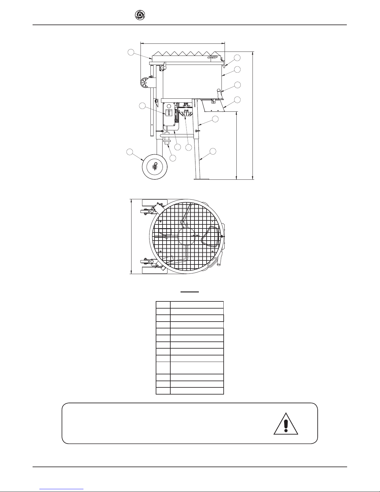
The machine is also equipped with a guard on its outlet to prevent ac-
cess to the mixing area (ref.11, g.1).
8. TRANSPORT
Use the machine’s handles (g.4) to move it; these must be pulled out
one at a time:
1. grasp a handle (ref.1, g.4) and remove its locking pin (ref.2, g.4).
2. Pull the handle (ref.1, g.4) fully upwards.
3. Fit the locking pin (ref.2, g.4).
Repeat with the other handle.
The mixer may also be moved with its four wheels (g.5).
- Before moving the mixer in this way, make sure the tank
guard safety hook (ref.12, fig.1) is engaged.
When lifting with a hoist or similar equipment, hook a four-point harness
into the holes on the frame (g.3). Make sure the harness has arms of
at least 1500 mm.
- Each arm of the harness must be rated for loads greater than
the total weight of the mixer.
- Always pull out its power plug before moving the mixer.
9. INSTALLATION
Unpack the machine.
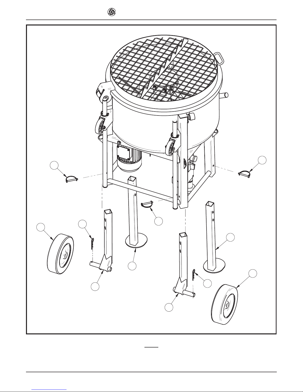
The machine is supplied with its legs removed, these must be assem-
bled:
1. Fit the wheels into the rear legs and lock them with their cotters.
2. Raise the mixer and t the front and rear legs; lock the legs at the
desired height with their lock pins. Follow the layout given in g.9.
The height of the mixer should enable easy unloading into the wheelbar-
row used to move the mixed product around the worksite.
- Place the mixer on a stable, level surface (max slope 5°, see
fig.2), so that it doesn’t sink into the ground or tip over when run-
ning.
- Leave at least 2 m clearance around the machine for handling
materials and product.
10. ELECTRICAL MAINS CONNECTION
- Make certain that a residual current device and miniature
circuit breaker are installed on the electrical power line.
10.1 Connecting versions with motor 115V/60Hz
Ensure that the supply voltage corresponds to machine dataplate speci-
cations. At full load it must be between 103V and 126V.
- To supply the machine it is necessary to use a 2-pole +
ground cable in order to ensure the machine's connection to the
site's equipotential system.
10.2 Sizing the power supply cable
The power supply line must be suitably sized to prevent voltage drops.
Do not use cable winders. The electric cable wire size must take into
account the operating currents and length of the line to avoid excessive
voltage drops (table 4).
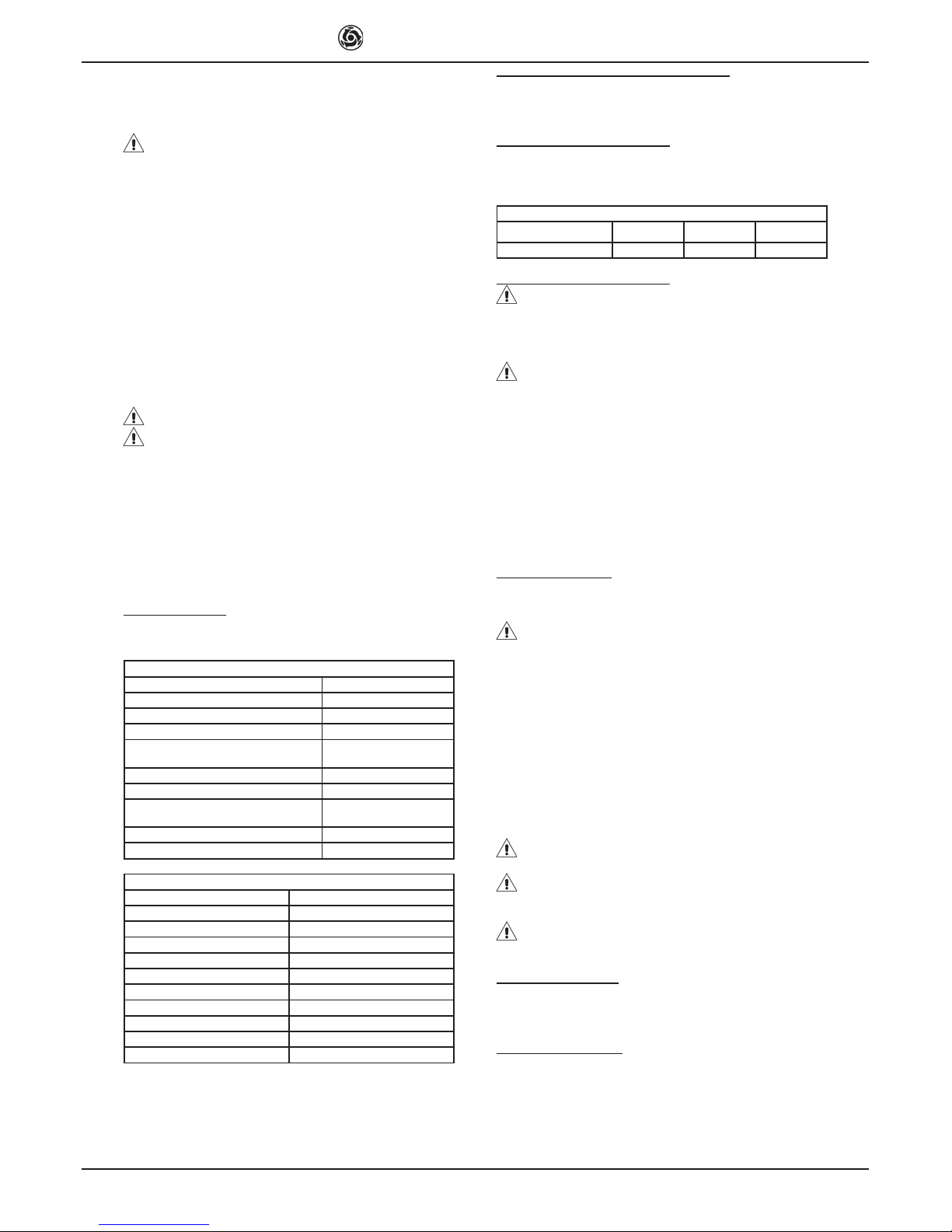
7DEOH
0RGHO 7\SHRIPR RU &DEOHPPð
MORTARMAN 120
PLUS
115 V
14.5 A 0 ÷ 12 13 ÷ 19 20 ÷ 30
&DEOH
OHQJ KP
The power supply cables used on the site must have an outer jacket that
is resistant to crushing, wear and weather (e.g. H07RN-F).
- For the conformity of the power supply, see CEI-64-8 (harmo-
nisation of CENELEC HD384).
11. COMMISSIONING THE MACHINE
Before connecting the machine to the electrical mains, ensure that all
safety devices are tted and are in perfect condition, that the extension
cord is in good condition and that the plugs and sockets (of the type
protected against jets of water) are not wet.
Connect the mains power cable to the plug on the electrical panel. Start
the mixer with the switch on the cabinet (ref.8, g.1).
- The motor is protected against overloads by a thermal cu-
tout. It stops the machine automatically if it overheats. Alloow the
motor to cool down before starting it up again.
12. EMERGENCY - STOP
- In case of emergency, stop the machine by pressing the
emergny button. Then pull out its power plug. To start again, re-
connect the power plug and turn the power switch to "1".
13. OPERATION
For best mixing results and regular operation, the mixer must be instal-
led on a level surface.
- Check that the machine stops as soon as the tank guard is
opened.
The machine must be started when the tank is empty.
- Do not start the machine when it is fully loaded.
The tank guard is equipped with bag breaker blades to facilitate using
premixed product. Load the mix components alternately, in the amounts
required for the type of product, so as to reduce mixing time as far as
possible.
- Load the material with the blades turning.
- Only load the specified products into the tank.
- Do not insert your hands or tools into the tank when the
blades are turning.
- Do not fill the tank beyond its mixing capacity (table 1).
Ruin the machine for as long as it takes to obtain an even mix of the
right consistency.
Empty the tank with the blades turning by opening its outlet by hand.
To do this, pull the lever (ref.1, g.6), for its full stroke, to position B.
To close the outlet, return the lever (ref.1, g.5) to position A.
- Make sure to place a container under the outlet before you
empty out the tank.
If any of the mix is left inside the tank for further use, the blades must
be left turning until it is used. We recommend leaving the mix inside the
tank as little as possible once it has reached the right consistency.
13.1 Blades jam while running
It may occur that the machine stops mixing because the mix is too den-
se.
To unjam the blades, proceed as follows:
1. Switch the machine off by setting the power switch (ref.8, g.1) to
"0".
2. Invert the direction of rotation of the blades by setting the switch
(ref.8, g.1) to "2".
3. Wait for a short time (5-10 seconds); then switch the machine off by
setting the power switch (ref.8, g.1) to "0".
4. Restore normal operation by turning the power switch (ref.8, g.1)
to "1".
- The machine only runs properly with the power switch set to
"1" (blades turn clockwise)
14. MAINTENANCE
- Maintenance must be done by adequately trained personnel,
after switching off the machine, disconnecting it from the power
supply and emptying the tank.
- Make sure the guards/safety equipment are always functio-
nal and in good condition.
Every two months of operation, check:
• the belt tension.
• the condition of the poly-V drive belt and pulleys.
Check weekly that the plug contacts on the electrical cabinet are clean,
dry and rust free.
- Periodically check the condition of the power cable jackets
exiting the cabinet.
- Periodically check, by raising the guard (ref.10, fig.1) 10 mm,

,0(5,17(51$7,21$/6S$
MORTARMAN 120 PLUS
that the machine stops as soon as the tank guard is opened.
14.1 Cleaning
Before a long work pause or at the end of the shift, the mixer tank must
be thoroughly cleaned by abundant washing. If you use a high-pressure
hose to clean the machine, do not aim the water jet directly at the plug/
socket connection or power switch.
- When manually cleaning the tank, make sure not to run the
machine.
- Do not dump the waste water on the site.
- If the guards are removed for cleaning, they must be reinstal-
led on completion.
Do not strike the tank with hammers, shovels, etc. Dents reduce the
effectiveness of mixing and also make the tank harder to clean.
14.2 Belt tension
1. Switch off the motor and disconnect the power plug.
2. Remove the belt guard (ref.2, g.7) by undoing the bolts securing it
(ref.1, g.7).
3. Loosen the 4 screws (ref.3, g.7) securing electric motor mount and
pull the belt (ref.5, g.7) with the screw (ref.4, g.7) if the tension is cor-
rect, applying a force of around F=1.5 kg at the centre of the belt’s free
section should displace it by around f=5 mm (g.8).
- Do not overtension the belt, as this reduces its life and that
of the reducer and motor bearings.
6. Once the belt is correctly tensioned, tighten down the 4 bolts (ref.3,
g.7).
7. Reinstall the belt guard (ref.2, g.7) with its bolts.
14.3 Replacing the belts
1. Switch off the motor and disconnect the power plug.
2. Remove the belt guard (ref.2, g.7) by undoing the bolts securing it
(ref.1, g.7).
3. Slacken off the 4 bolts (ref.3, g.7) securing the motor mount and
slacken off the belts (ref.5, g.7) with the screw (ref.4, g.7) until they
can be slipped off the motor and drive reducer pulleys.
4. Fit the new belts, rst onto the reducer pulley and then onto the motor
pulley.
5. Tension the belts (ref.5, g.7) with the screw (ref.4, g.7): if the ten-
sion is correct, applying a force of around F=1,5 kg at the centre of the
belt’s free section should displace it by around f=5mm (g.8).
6. Once the belt is correctly tensioned, tighten down the 4 bolts (ref.3,
g.7).
7. Reinstall the belt guard (ref.2, g.7) with its bolts.
Check the belt tension again after the rst 4 hours of operation with the
new belts, and repeat the check every 18-20 hours.
14.6 Removing the outlet guard
1. Undo the bolts (ref.20, g.1) and remove the guard (ref.24, g.1).
2. To ret the guard (ref.24, g.1) align its holes with the mount holes
and reinstall the bolts (ref.20, g.1).
14.7. REPAIRS
Repairs must be done exclusively by specialised personnel.
Use exclusively original IMER spare parts; modications to parts are
strictly prohibited.
- Never start up the mixing machine during repairs.
- If any guards are removed for repairs, ensure they are cor-
rectly refitted at the end of work.
15. RESIDUAL RISKS AND SAFETY NOTICES
Although the machine is constructed in line with established legislation,
certain residual risks cannot be eliminated and require the use of indivi-
dual safety equipment. The machine is equipped with notices to indicate
the residual risks and how to avoid them.
NOISE HAZARD
Wear ear defenders
HAND CRUSHING/SHEARING HAZARD
Wear gloves
EYE INJURY HAZARD
Wear safety glasses
INCORRECT USE HAZARD
Read the manual before operating the machine
TRAPPING/CRUSHING AND SHEARING HAZARD
Do not remove the guards
Do not touch drive components
ELECTROCUTION HAZARD
Danger - electrical power
Note that the employer is responsible for ensuring his workers use indi-
vidual safety equipment.
16. TROUBLESHOOTING
- CAUTION! All maintenance operations must be performed
exclusively with the machine switched off, with the selector set to
"0" and the power plug disconnected from the mains.
)DXO &DXVH 5HPHG\
Motor does not start
when switch is turned
Defective power cable Check power cables *
Plug not inserted in
socket correctly
Ensure correct
connection
Power cable from
plug to control panel
detached
Remake the connection *
Loose wire inside motor
circuit board
Remake the connection *
Loose wire inside motor
circuit board
Remake the connection *
Limit switch malfunction Replace limit switch *
Faulty main switch Replace switch *
The overload safety
device has been
activated
Wait for a few minutes
and then try restarting
the machine
Tank guard open Close tank guard
Outlet does not open Blocked outlet guard Remove and clean outlet
guard
During mixing, the
blades slow down or jam
Belts are worn or slack Tension or replace the
belts
2SHUD LRQ REHFDUULHGRX E\DQHOHF ULFLDQ

,0(5,17(51$7,21$/6S$
MORTARMAN 120 PLUS
0$; )
I
)LJ )LJ )LJ
Õ
Ö
1
2
Õ
)LJ )LJ
A
Ù
B
1
4
2
1
3
5
)LJ )LJ

,0(5,17(51$7,21$/6S$
MORTARMAN 120 PLUS
5
66
6
4
4
1
1
2
5
3
)LJ

,0(5,17(51$7,21$/6S$
MORTARMAN 120 PLUS
4
12
14
15
20
20
24
25
28
31
26
27
1
29
16
30
3
34
3
5
18
11
19
6
23
28
13
10
7
21
9
8
7
16
33
2
22
17
32
36
35
7$9

,0(5,17(51$7,21$/6S$
MORTARMAN 120 PLUS
7$9
6758&785(0$&+,1(
5() &2'( '(6&5,37,21 127(6
1 3214791 LIMIT SWITCH
2 2222144 BOLT TE 8.8 5737 M10X55 Z
3 2222465 BOLT TRILOB. TC PH M5X15 N
4 2222601 BOLT TSPEI 10.9 5933 M10X30 Z
5 2223352 NUT 5588 M5 Z
6 2223570 NUT 5588 M8 Z
7 2223920 NUT AUTOBL. 7474 M10
8 2223923 NUT AUTOBL. 7473 M8
9 2224204 WASHER 6593 D.8X24 Z
10 2224260 WASHER 6593 D.10X30 Z
11 2226700 SPLIT PIN AMA 3.5/72
12 2235452 CAP
13 3201339 BOLT TSPEI 5933 M8X25 Z
14 3205257 WHEEL
15 3208452 CAP
16 3231248 PIN 10X70 Z
17 3225175 BOLT 5927 M5X10 Z
18 3226342 WHEEL
19 3229797 CAPACITOR 100 MF 250V
20 3227870 BOLT TRILOB. TEFR 5739 M8X16 Z
21 3229553 FRAME
22 3229559 OUTLET
23 3229566 FRONT LEG
24 3229598 OUTLET PROTECTION
25 3229602 TANK
26 3229773 RH REAR LEG
27 3229775 LH REAR LEG
28 3229778 HANDGRIP
29 3229783 SUPPORT
30 32 ELECTRIC PANEL
31 3229800 PIN 8X45 Z
32 3201216 CABLE CLAMP PG 13.5
33 3210099 BOLT TRILOB.TEFR 6X25 Z
34 3209728 BOLT TRILOB.TC PH M6X15 N
35 3234519 CAM
36 3234521 SPACER

,0(5,17(51$7,21$/6S$
MORTARMAN 120 PLUS
24
9
11
13
15
16
17
18
20
21
22
23
10
11
52
14
12
7
1
8
4
19
3
6
25
25
25
7$9

,0(5,17(51$7,21$/6S$
MORTARMAN 120 PLUS
7$9
7$1.
5() &2'( '(6&5,37,21 127(6
1 2222034 BOLT TE 8.8 5739 M12X20 Z
2 2222142 BOLT TE 8.8 5737 M12X100 Z
3 2222540 BOLT TCEI 5931 M6X20 Z
4 2223836 NUT 5589 M30X2
5 2223921 NUT AUTOBL. 7474 M12
6 2223924 NUT AUTOBL. 7474 M6
7 2224049 WASHER 6593 D.6X24
8 2224380 WASHER 6592 D.12X25 Z
9 2224900 WASHER DEV 8842 A12 Z
10 2229555 KEY 10X8X40
11 3206904 WASHER D.12X36
12 3225750 BOLT TRILOB. TEFR M6X10 Z
13 3229562 DIFFUSER
14 3234511 TANK PROTECTION
15 3229588 OUTER BLADE
16 3229594 INNER BLADE
17 3229602 TANK
18 3229622 WASHER D.13X40X3
19 3234518 SAFETY HOOK
20 3230009 MIXER HEAD
21 3230013 SCRAPER
22 3230020 SCRAPER RUBBER
23 3230023 MIDDLE BLADE
24 2222586 BOLT TSPEI 10.9 5933 M8X16 Z
25 2222007 BOLT TE 8.8 5739 M12X35 Z

,0(5,17(51$7,21$/6S$
MORTARMAN 120 PLUS
1
2
3
4
5
6
7
8
910
11
12
13
7$9
75$160,66,21
5() &2'( '(6&5,37,21 127(6
1 2222420 BOLT AUTOF. TE 6950 D.4,8X13 Z
2 2222599 BOLT TSPEI 10.9 5933 M10 X16 Z
3 2224204 WASHER 6593 D.8X24 Z
4 2227310 STOP RING E 19
5 2229310 KEY 6X6X30
6 3226385 GEAR BOX
7 3227870 BOLT TRILOB. TEFR 5739 M8X16 Z
8 3229828 MOTOR
9 3229795 PULLEY
10 3229599 MOTOR SUPPORT
11 3229605 GUARD
12 3229609 BELT
13 3262752 BOLT TE 8.8 5737 M8X80 Z

,0(5,17(51$7,21$/6S$
MORTARMAN 120 PLUS
10
2
24
33
19
11
31
6
8
26
32
30
17
27
23
95
12
15
1
18
14
25
3
22
21
16
8
8
7
4
20
29
34
7$9
*($5%2;
5() &2'( '(6&5,37,21 127(6
1 3209514 GEAR BOX CASING
2 2204569 BEARING 6211
3 3213282 BEARING 6208
4 3226384 MAIN SHAFT
5 3208970 GEAR
6 3208983 BEARING 6204
7 3213178 KEY 10X8X20
8 3209682 BEARING 6302
9 3208966 SPACER BRACKET
10 1227330 STOP RING E 15
11 2227207 STOP RING E 55
12 3208975 PINION
13 2229250 KEY 5X5X15
14 3209801 GEAR
15 3208979 PULLEY
16 3226386 GEAR BOX CASING
17 2227320 STOP RING E 20
18 3209799 SHAFT
19 2224340 WASHER 6592 D.10X21 Z
20 2223650 NUT 5588 M10
21 2222145 BOLT 5737 M10X80 Z
22 3226388 OIL SEAL 90X55X10
23 3200094 OIL SEAL 35X20X7
24 2222148 BOLT 5737 M10X65 Z
25 3209811 GASKET
26 3213180 PIN D.8X30
27 2229259 KEY 6X6X14
28 3226390 BUSHING
29 2204505 BEARING 6008
30 1222694 BOLT 5737 M10X110 Z
31 2229555 KEY 10X8X40
32 3226451 PIN D.5X16
33 2223836 NUT 5589 M30X2
34 3234539 SPACER

,0(5,17(51$7,21$/6S$
MORTARMAN 120 PLUS
7$9
1
2
3
4
5
6
6
7$9
(/(&75,&3$1(/
5() &2'( '(6&5,37,21 127(6
1
3209542 PLUG + ELECTRIC CABLE
2 3225237 SAFETY CATCH BUTTON
3 3230439 CONTACTOR
4
3227796 INVERTER
5 3230076 RESISTOR
6 3230081 JUNCTION BOX
7$9
11-12
9-10
7-8
3-4
5-6
1-2
KM1
3
4
1
2
INVERTITORE
10
IM1
2
C1
MARCIA NERO
ROSSO
1
0
2
1,5
mmq.
S5
6
R1 3
U2 4
T97
V8 W10
IM1
INVERTITORE
DI
MARCIA
AVVIAM. MARRONE
A1
KM1
A2
12
11
IM1
13
14 KM1
TM1
FCS
CELESTE
CELESTE
MARRONE
(3)-VIOLA
EMERGENZA
P1
(4)-GIALLO(5)-ARANCIO
SENSORE
MAGNETICO ESTERNO
AL QUADRO
(3)
(2)
R1
MOTORE
ELETTRICO
F1
5x20 1A
(1)- BIANCO
SPINA MOBILE
5-15P 2P+T 15A -125V
(L) - BIANCO
(N) - NERO
(U) - MARRONE
(V1) - CELESTE
(V) - CELESTE
( U1) - MARRONE
(2) - CELESTE
(7) - BIANCO (6) - BIANCO
(V2) - NERO
(U2) - ROSSO
7$9
:,5,1*',$*5$0
5() '(6&5,37,21 127(6
P1 SAFETY CATCH BUTTON
F1 FUSE CARRIER 5X20 1A
IM1 INVERTER
KM1 CONTACTOR
FCS LIMIT SWITCH
TM1 THERMAL PROTECTION
C1 CAPACITOR 100 F (250V 60Hz)
R1 RESISTOR 33 K (10W 750V)

,0(5,17(51$7,21$/6S$
MORTARMAN 120 PLUS
ONE YEAR WARRANTY
We warrant to the original purchaser that the IMER equipment described herein (the "equi-
pment") shall be free from defects in material and workmanship under normal use and
service for which it was intended for a period of one (1) year from the date of purchase by
the original purchaser.
Our obbligation under this warranty is expressely limited to replacing or repairing, free of
charge, F.O.B. our designated service facility, such part or parts of the equipment as our
inspection shall disclose to be defective. Parts such as engines, motors, pumps, valves,
electric motors, etc. furnished by us but not manifactured by us will carry only the warranty
of the manifacturer. Transportation charges or duties shall be borne by the purchaser. This
shall be the limit of our liability with respect to the quality of the equipment.
This warranty shall not apply to any equipment, or parts thereof, which has been damaged
by reason of accident, negligence, unreasonable use, faulty repairs, or which has not been
mantained and operated in accordance with our printed instructions for our equipment.
Further, this warranty is void if the equipment, or any of its components, is altered or modi-
ed in any way.
THIS WARRANTY IS EXPRESSLY IN LIEU OF ALL OTHER WARRANTIES, EXPRES-
SED OR IMPLIED, INCLUDING ANY IMPLIED WARRANTY OF MERCHANTABILITY OF
FITNESS FOR A PARTICULAR PURPOSE.
We make no other warranty, representation or guarantee, nor is anyone authorized to
make one on our behalf. We shall not be liable for any consequential damage of any kind,
including loss or damage resulting, directly or indirectly, from the use or loss of use of the
machine. Without limiting the generality of the foregoing, this exclusion from liability em-
braces the purchase's expenses for downtime, damages for which the purchaser may be
liable to other persons, damages to property, and injury or death of any persons.
This warranty shall not be deemed to cover maintenance parts, including but not limited
to blades, belts, hoses, hydraulic oil or lters, for which we shall have no responsability or
liability whatsoever.
,0(5 U.S.A. Inc.
221 Westhampton Place
Capitol Heights, MD 20743
Ph. 301.336.3700
Fax 301.336.6687
Toll Free: 800.275.5463
www.imerusa.com
Table of contents
Other IMER Mixer manuals