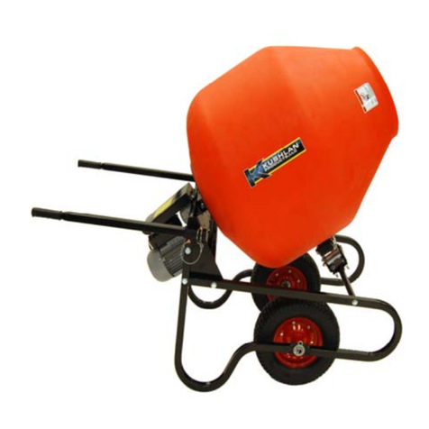
IMER ROLLBETA 1105402 Guide

(1105402 - 1105402A - 1105403 - 1105404 - 1105412 - 1105413 - 1105414 -1105427)
EL
ROLLBETA
IMER INTERNATIONAL S.p.A.
Via Salceto, 55 - 53036 Poggibonsi (SI) - Italy
Tel. +39 0577 97341 - Fax +39 0577 983304
www.imergroup.com
BETONIERA
Manuale uso manutenzione ricambi
BETONIERRE
Manuel utilisation entretien pieces de rechange
CONCRETE MIXER
Operating, maintenance, spare parts manual
BETONMISCHER
Handbuch für Bedienung, Wartung und Ersatzteile
HORMIGONERA
Manual de uso, mantenimiento y recambios
3210896 R06- 2016/04

2
IMER INTERNATIONAL S.p.A.
ROLLBETA
Fig.1
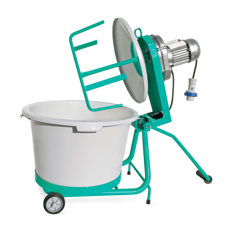
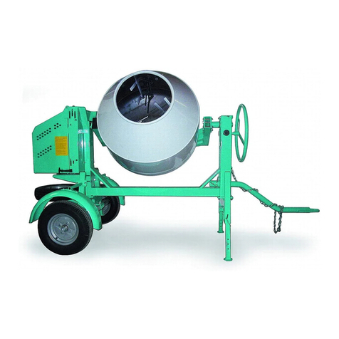
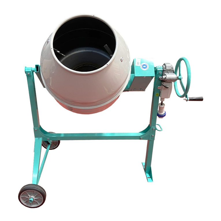
1 MIXING DRUM
2 PLUG/SWITCH UNIT
3 DRUM TIPPING LEVER
4 GEARMOTOR
5 GEARMOTOR MOUNTING FRAME
6 WHEEL
1 TAMBOR DE MEZCLA
2 GRUPO CLAVIJA-INTERRUPTOR
3 PALANCA PARA VOLCAR EL TAMBOR
4 MOTORREDUCTOR
5 BASTIDOR DE SOPORTE DEL
MOTORREDUCTOR
6 RUEDA
1 MISCHTROMMEL
2 SCHALKASTEN
3 KIPPHEBEL FÜR TROMMEL
4 GETRIBEMOTOR
5 GETRIEBEMOTORGESTELL
6 RAD
1 VASCA DI MESCOLAMENTO
2 GRUPPO SPINA - INTERRUTTORE
3 MANIGLIA RIBALTAMENTO VASCA
4 MOTORIDUTTORE
5 TELAIO SUPPORTO MOTORIDUTTORE
6 RUOTA
1 CUVE DE MALAXAGE
2 GROUPE FICHE-INTERRUPTEUR
3 LEVIER BASCULEMENT CUVE
4 MOTORÉDUCTEUR
5 CHÂSSIS SUPPORT MOTORÉDUCTEUR
6 ROUE
Particolare attenzione deve essere fatta alle avvertenze contrassegnate con questo simbolo :
Il faut prêter une attention toute particulière aux notes précédées de ce symbole:
Special attention must be given to warnings with this symbol:
Lesen Sie die mit diesem Symbol bezeichneten Abschnitte mit besonderer Aufmerksamkeit:
Se tiene que prestar una atención especial a las indicaciones marcadas con el signo:
TABELLA - TABLEAU - TABLE - TABELLE - TABLA 1
I F GB D E
CODICE MACCHINA DONNEES TECHNIQUES TECHNICAL DATA TECHNISCHE DATEN DATO TECNICOS
CODICE MACCHINA CODE BÉTONNIÈRE CONCRETE MIXER CODE CODENUMMER DES
BETONMISCHERS
CÓDIGO DE LA
HORMIGONERA
1105402 (230V/50 Hz)
1105403 HDPE (230V/50HZ)
1105404 (230V/50 Hz) Rig
1105412 (110 V / 50 Hz)
1105413 HDPE (110V/50HZ)
1105414 (110V/50 Hz) Rig
1105402A (230V/50 Hz)
1105427 (220V/60Hz)
VOLUME VASCA
MISCELAZIONE VOLUME CUVE MALAXAGE MIXER DRUM VOLUME VOLUMEN DER MISCHTROMMEL VOLUMEN DEL TAMBOR
DE MEZCLA l 134
CAPACITÀ D' IMPASTO CAPACITÉ DE MALAXAGE MIX CAPACITY MISCHLEISTUNG CAPACIDAD DE MEZCLA l ~ 100
RESA EFFETTIVA RENDEMENT EFFECTIF EFFECTIVE OUTPUT ISTLEISTUNG RENDIMIENTO EFECTIVO l ~ 60
DIAMETRO VASCA DIAMÈTRE CUVE DRUM DIAMETER TROMMELDURCHMESSER DIÁMETRO DEL TAMBOR mm 610
N° GIRI VASCA NOMBRE TOURS CUVE DRUM RPM TROMMELDREHZAHL Nº DE REVOLUCIONES
DEL TAMBOR n° / 1' 21
DIREZIONE ROTA-
ZIONE VASCA (VISTO
DALLA BOCCA DI SCA-
RICO): ANTIORARIO
DIRECTION ROTATION CUVE (VUE
DU CÔTÉ DE LA BOUCHE D'ÉVA-
CUATION): SENS INVERSE DES
AIGUILLES D'UNE
MONTRE
DRUM ROTATION DI-
RECTION
(SEEN FROM MOUTH OF
DRUM): ANTI-CLOCKWISE
TROMMELDREHRICHTUNG (VON
DER FÜLLÖFFNUNG GESEHEN) :
ENTGEGEN DEMUHRZEIGERSINN
DIRECCIÓN DE RO-
TACIÓN DEL TAMBOR
(VISTO DESDE LA BOCA
DE DESCARGA): ANTIHO-
RARIO
DIMENSIONI RUOTE DIMENSIONS ROUES WHEEL DIMENSIONS RADABMESSUNGEN DIMENSIONES DE LAS
RUEDAS mm Ø370x60 pneumatica
385X90 rigida
POTENZA MOTORE
ELETTRICO PUISSANCE MOTEUR MOTOR POWER MOTORLEISTUNG POTENCIA MOTOR Kw 0.3
ALIMENTAZIONE
ELETTRICA ALIMENTATION NOM. VOLTAGE SPANNUNG ALIMENTACIÓN V / Hz 230 / 50
110 /50
ASSORBIMENTO ABSORPTION NOM. CURRENT STROMAUFNAHME CONSUMO A 2.8 (230 V)
6 (110 V)
NUMERO DEI GIRI DEL
MOTORE ELETTRICO
NOMBRE DE TOURS MOTEUR
ÉLECTRIQUE
NUMBER OF ELECTRIC
MOTOR RPM'S
DREHZAHL DES
ELEKTROMOTORS
RÉGIMEN DEL MOTOR
ELÉCTRICO n° / 1' 2.750
GRADO DI PROTE-
ZIONE DEGRÉ DE PROTECTION PROTECTION GRADE SCHUTZKLASSEE GRADO DE PROTECCIÓN IP 55
PESO DELLA
MACCHINA POIDS DE LA MACHINE MACHINE WEIGHT MASCHINENGEWICHT PESO DE LA MÁQUINA kg 46
DIMENSIONI IMBALLO DIMENSIONS EMBALLAGE PACKING DIMENSIONS AUSSENMASSE DER
VERPACKUNGIN
DIMENSIONES DEL
EMBALAJE mm 660x730x700

3
IMER INTERNATIONAL S.p.A.
ROLLBETA
Gentile Cliente,
ci complimentiamo per il suo acquisto: la betoniera IMER, risultato
GLDQQLGLHVSHULHQ]DqXQDPDFFKLQDGLPDVVLPDDI¿GDELOLWjH
dotata di soluzione tecniche innovative.
- OPERARE IN SICUREZZA.
(¶IRQGDPHQWDOHDL¿QLGHOODVLFXUH]]DOHJJHUHDWWHQWDPHQWH
le seguenti istruzioni.
Il presente manuale di USO E MANUTENZIONE deve essere
custodito dal responsabile di cantiere, nella persona del Ca-
pocantiere, nel cantiere stesso, sempre disponibile per la sua
consultazione.
Il manuale è da considerarsi parte della macchina e deve essere
FRQVHUYDWRSHUIXWXULULIHULPHQWL(1¿QRDOODGLVWUX]LRQH
della macchina stessa. In caso di danneggiamento o smarrimento
potrà essere richiesto al costruttore un nuovo esemplare.
Il manuale contiene la dichiarazione di conformità CE 98/37/CE
ed importanti indicazioni sulla preparazione del cantiere, l’instal-
lazione, l’uso, le modalità di manutenzione e la richiesta di parti di
ricambio. Comunque è da ritenersi indispensabile una adeguata
esperienza e conoscenza della macchina da parte del montatore
e dell’utilizzatore.
$I¿QFKq VLD SRVVLELOH JDUDQWLUH OD VLFXUH]]D GHOO¶RSHUDWRUH OD
sicurezza di funzionamento e una lunga durata della macchina
devono essere rispettate le istruzioni del manuale, unitamente
alle norme di sicurezza e prevenzione degli infortuni sul lavoro
secondo la legislazione vigente (uso di calzature e abbigliamento
adeguati, uso di elmetti, guanti, occhiali, ecc.).
- Mantenere sempre leggibili le avvertenze.
(¶YLHWDWRDSSRUWDUHPRGL¿FKHGLTXDOVLDVLQDWXUDDOOD
struttura metallica o impiantistica della betoniera.
IMER INTERNATIONAL declina ogni responsabilità in caso di
non osservanza delle leggi che regolano l’uso di tali apparecchi,
in particolare: uso improprio, difetti di alimentazione, carenza di
PDQXWHQ]LRQHPRGL¿FKHQRQDXWRUL]]DWHLQRVVHUYDQ]DSDU]LDOH
o totale delle istruzioni contenute in questo manuale.
,0(5,17(51$7,21$/KDLOGLULWWRGLPRGL¿FDUHOHFDUDWWHULVWLFKH
della betoniera e/o i contenuti del presente manuale, senza l’ob-
bligo di aggiornare la macchina e/o i manuali precedenti.
1. DATI TECNICI
- La betoniera ROLLBETA ha la protezione elettrica di
classe II, a doppio isolamento ( ).
Nella tabella 1 sono riportati i dati tecnici della betoniera, facendo
ULIHULPHQWRDOOD¿JXUD
2. NORME DI PROGETTO
Le betoniere sono state progettate e costruite applicando le se-
guenti norme: EN 292-1-2; EN 60204-1; prEN 12151.
3. LIVELLO EMISSIONE SONORA
In tabella 2 sono riportati il livello di pressione sonora della be-
toniera, misurato all'orecchio dell'operatore (LpA a 1 m - 98/37/
CE) ed livello di emissione sonora nell'ambiente (potenza LWA)
misurato secondo EN ISO 3744 (2000/14/CE).
4. DESCRIZIONE E MONTAGGIO DELLA BETONIERA.
- La betoniera è destinata per l'impiego nei cantieri edili,
per ottenere impasti di calcestruzzi, malte, cementizi, ecc.
4.1 DESCRIZIONE BETONIERA (Fig. 1)
La betoniera è costituita da un telaio (rif. 5) con due ruote (rif. 6),
due maniglie (rif. 3) per il ribaltamento e la movimentazione in
cantiere. Sul telaio è montato il motoriduttore (rif. 4), che fa ruotare
la vasca di mescolamento (rif. 1).
Il gruppo spina d'alimentazione elettrica ed interruttore sono posti
sopra il motore elettrico (rif. 2).
4.2 MONTAGGIO BETONIERA
La betoniera IMER si presenta tutta smontata all’interno di una scatola.
Togliere dalla vasca tutti i componenti della macchina.
Fig. 2) - Serrare le maniglie di ribaltamento (rif.1) con il telaio
(rif.2) con i dadi (rif.3) e viti (rif.4) interponendo le rondelle (rif.5).
Inserire le ruote (rif. 6) con le copiglie (rif. 7).
Fig. 3) - Serrare con i dadi (rif.3) nel telaio (rif.2) il motoriduttore
(rif.1).
Fig. 4) - Centrare la boccola della vasca con l'albero del moto-
riduttore.
- Attenzione. L'asola presente nella boccola della vasca
deve incastrarsi nella spina presente sull'albero del moto-
riduttore.
Interporre la rondella (rif. 2) e serrare a fondo la vite (rif. 1).
Fig. 5) - Posizionare le pale all'interno della vasca e bloccarle con
dadi e viti (usare chiave n° 19).
5. SICUREZZA OPERATIVA
- Prima di utilizzare la betoniera accertarsi che sia munita
di tutti i dispositivi di protezione.
- E' vietato introdurre parti del corpo e/o utensili nella
vasca di miscelazione in funzione.
Nell’area di lavoro devono essere osservate le norme per la
prevenzione degli infortuni nonchè le disposizioni di sicurezza.
Occorre fare attenzione durante la manipolazione dei componenti
necessari alla preparazione delle malte, di non sollevare polvere
per evitare di inalarne; se ciò non fosse possibile è necessario
indossare una maschera per la protezione della bocca e del naso.
- Non deve essere usata in ambienti ove esista pericolo
di esplosioni o incendio o in ambienti di scavi sotterranei.
La betoniera non dispone di illuminazione propria e pertanto il
OXRJRGLODYRURGHYHHVVHUHVXI¿FHQWHPHQWHLOOXPLQDWR
Le linee di alimentazione devono essere posate in modo tale da
non poter essere danneggiate. Non collocare la betoniera sul cavo
di alimentazione elettrica.
L'allacciamento elettrico deve essere tale da impedire la pene-
trazione di acqua nei connettori. Impiegare soltanto connettori ed
attacchi muniti di protezione contro gli spruzzi d’acqua.
- Non utilizzare linee elettriche inadeguate, provvisorie: eventual-
mente consultarsi con personale specializzato.
- Le riparazioni degli impianti elettrici devono essere eseguite
esclusivamente da personale specializzato. Sconnettere la mac-
china dall'alimentazione od arrestare il motore prima di eseguire
le operazioni di manutenzione o riparazione.
-
Evitare che i conduttori elettrici possano andare a contatto con parti
mobili e/o in movimento della macchina e quindi lesionandosi mettere
in tensione parti metalliche.
6. SICUREZZA ELETTRICA
La betoniera ROLLBETA a doppio isolamento è realizzata secondo
la norma EN 60204-1, è protetta contro gli spruzzi d'acqua (IP 55) ed
è dotata di protezione contro i sovraccarichi e di minima tensione.
La betoniera è dotata di una protezione contro i contatti elettrici acci-
dentali, realizzata con un doppio isolamento di classe II delle parti in
tensione. Pertanto non richiede di essere collegato al circuito di terra.
- ATTENZIONE: in caso di riparazioni, la classe II di
protezione è mantenuta soltanto se utilizzati degli isolanti
originali e che le distanze ed i materiali d'isolamento non
VLDQRPRGL¿FDWL
7. SICUREZZA MECCANICA
Nella betoniera IMER i punti pericolosi sono protetti mediante
opportuni dispositivi di protezione, che devono essere mantenuti
in perfette condizioni e montati, come ad esempio la protezione
della ventola di raffreddamento del motore elettrico.
8. TRASPORTABILITÀ
- La betoniera non deve essere trainata su strada da
veicoli, dato che le ruote sono adatte per spostamenti nei
cantieri per brevi tratti.
Per la movimentazione manuale della betoniera in cantiere, uti-
OL]]DUHOHDSSRVLWHPDQLJOLHULI¿JHWUDVODUHFRPHLQGLFDWR
LQ¿J
- ATTENZIONE: prima di spostare la betoniera, staccare
sempre la spina d'alimentazione elettrica.
9. INSTALLAZIONE
- Installare la betoniera in piano e su fondo stabile (mas-
sima inclinazione ammessa 5°, come da Fig. 7), per evitare
che affondi nel terreno o si ribalti durante il funzionamento.
0217$**,2&$9$//(772237,21$/¿J
La betoniera ROLLBETA può essere montata su un apposito
II
Istruzioni originali

4
IMER INTERNATIONAL S.p.A.
ROLLBETA
cavalletto (cod. 1105490) allo scopo di alzarla di circa 50 cm dal
suolo e poter scaricare l'impasto dentro una carriola. La betoniera
sopra il cavalletto non può essere movimentata in cantiere.
Il cavalletto viene fornito smontato dentro una scatola. Ruotare il
FDYDOOHWWRLQWHUQRULVSHWWRDOOHVWHUQRULI¿QRDIDUFRLQFLGHUHL
due fori, quindi inseriere la copiglia (rif. 2). Inserire il supporto (rif.
3) sul perno sopra i cavalletti: il cavalletto è pronto.
Inserire l'assale delle ruote della betoniera ROLLBETA nelle 2
DVROHULIHGDSSRJJLDUHLOWHODLRVXOVXSSRUWR¿J
Per scaricare la betoniera agire sulle maniglie di ribaltamento:
quando è nella posizione di scarico, ruotare la leva di bloccaggio
ULI¿JSHULPSHGLUHGLULWRUQDUHQHOODSRVL]LRQHLQL]LDOH
11. ALLACCIAMENTO ELETTRICO
-
9HUL¿FDUHFKHODWHQVLRQHGDOLPHQWD]LRQHHODIUHTXHQ]D
di rete siano conformi ai dati di targa della macchina, quando è
in funzione con il carico max.
La linea di alimentazione elettrica deve essere provvista di
protezione contro le sovracorrenti (es. con un interruttore ma-
gnetotermico) e contro i contatti indiretti (es. con un interruttore
tipo differenziale). Il dimensionamento dei conduttori del cavo di
alimentazione elettrica deve tener conto delle correnti di funziona-
mento e della lunghezza della linea per evitare eccessive cadute
di tensione (rif. Tab. 3).
Evitare l’impiego di prolunghe avvolte a spire sui tamburi. Il conduttore
di alimentazione deve essere del tipo adatto per frequenti movimenti
e rivestimento resistente all'abrasione (per esempio H07RN-F).
Collegare l'alimentazione alla spina della betoniera posta sul qua-
GURHOHWWULFRULI¿JDYYLWDQGRODJKLHUDGLULWHJQRPHFFDQLFR
con grado di protezione IP67.
- La betoniera è così pronta per poter lavorare.
12. MESSA IN MARCIA
3ULPD GL FROOHJDUH HOHWWULFDPHQWH OD EHWRQLHUD YHUL¿FDUH FKH WXWWL L
dispositivi di sicurezza siano a posto ed in buono stato d'uso, che la
prolunga sia in buono stato e che le spine e prese (del tipo protetto
contro getti d'acqua) non siano bagnate
Collegare il cavo di alimentazione elettrica alla spina del quadro elet-
trico.
Avviare la betoniera mediante l’interruttore posto sul quadro
HOHWWULFRULI¿JFRPSRVWRGDGXHWDVWLYHUGHSHUODFFHQ-
sione, rosso per l'arresto. L’interruttore è dotato di protezione di
PLQLPDWHQVLRQHQHLFDVLLQFXLVLVLDYHUL¿FDWDXQDPDQFDQ]D
d'alimentazione per cause accidentali, occorre ripremere il pul-
sante d'avviamento verde.
In caso di emergenza, per arrestare la macchina, premere il
pulsante di arresto di colore rosso (sporgente), quindi staccare la
spina di alimentazione elettrica.
PROTEZIONE TERMICA:
-
Il motore elettrico è protetto dai sovraccarichi da una son-
da termica: in caso di surriscaldamento si arresta con sgancio
dell'interruttore. Far raffreddare il motore ed avviare di nuovo.
13. MODALITÀ D'USO
-
È vietato introdurre parti del corpo e/o utensili all'interno
della vasca di miscelazione in funzione.
-
Assicurarsi che la rotazione della vasca sia in senso an-
tiorario (visto dalla bocca di scarico).
Introdurre i materiali con la vasca in rotazione.
Prima di iniziare ad introdurre i materiali all'interno della vasca è
conveniente versare una certa quantità di acqua. Il caricamento
deve essere effettuato alternando i vari materiali da mescolare,
nelle quantità desiderate per il tipo d’impasto che si vuole ottenere,
allo scopo di ridurre al minimo il tempo di mescolamento.
Far ruotare la vasca per un tempo necessario ad ottenere un
impasto omogeneo, della consistenza desiderata.
Lo svuotamento deve essere effettuato con la vasca di miscela-
zione in funzione, inclinando la bocca della vasca verso il basso,
UXRWDQGROHDSSRVLWHPDQLJOLHULI¿J
- Nell'operazione di scarico occorre tenere ben salde le
due maniglie di ribaltamento.
/DYDVFDGHOODEHWRQLHUD,0(5KDGXHSRVL]LRQL¿VVHXQDGLPLVFH-
lazione (bocca del tamburo rivolta verso l’alto) e una di svuotamento
del tamburo (bocca del tamburo rivolta verso il basso).
Tutte le operazioni di movimento della vasca sono comandate dalle
due maniglie di ribaltamento.
-
Evitare di mettere in moto la betoniera a pieno carico.
14. MANUTENZIONE
- Le operazioni di manutenzione devono essere eseguite
da personale esperto, dopo aver spento il motore elettrico,
scollegata l'alimentazione elettrica e svuotata la vasca di
mescolamento.
Controllare ogni due mesi di lavoro:
- serraggio della vite che blocca la vasca sul riduttore;
JRQ¿DUHOHUXRWHDOODSUHVVLRQHLQGLFDWDVXOFHUFKLRQH
- pulire i fori di ingresso aria di raffreddamento del motore elettrico
da detriti e sporcizia.
Controllare settimanalmente che i contatti della spina posta sul
quadro elettrico siano ben puliti,asciutti e privi di ossidazioni.
14.1 PULIZIA
Prima di una lunga pausa di lavoro o al termine del lavoro quotidia-
no, la vasca di miscelazione deve essere pulita a fondo all’interno
ed all’esterno.
- Quando si esegue la pulizia manuale, non si deve met-
tere in funzione la betoniera.
- Se per la pulizia vengono rimosse le coperture di pro-
WH]LRQHDOOD¿QHGHLODYRULRFFRUUHULPRQWDUOHFRUUHWWDPHQWH
Se la pulizia viene eseguita mediante getti d’acqua, non indirizzare
questi ultimi direttamente sul gruppo spina-interruttore.
14.2 Indicazioni per la pulizia
Pulire la betoniera all’esterno con una spazzola e acqua. Raschia-
re le incrostazioni di calcestruzzo e malta.
All’interno della vasca non devono formarsi incrostazioni di calce-
struzzo e malta. L’interno della vasca si pulisce meglio se, prima
di lunghe pause e/o al termine del lavoro, si fa funzionare la vasca
con alcune palate di ghiaia ed acqua. In tal modo si impedisce
l’indurimento dei residui di calcestruzzo o malta.
La vasca di miscelazione non deve essere colpita con oggetti duri
come martelli, pale ecc.
La vasca di miscelazione ammaccata peg-
JLRUDLOSURFHGLPHQWRGLPLVFHOD]LRQHHGqDQFKHSLGLI¿FLOHGDSXOLUH
.
14.3 RIPARAZIONE
- Non mettere in funzione la betoniera durante i lavori
di riparazione.
Le riparazioni degli impianti elettrici possono essere eseguite
esclusivamente da personale specializzato.
I ricambi da utilizzare devono essere esclusivamente ricambi
RULJLQDOL,0(5HQRQSRVVRQRHVVHUHPRGL¿FDWL
- Se per eseguire le riparazioni vengono rimosse le
coperture di protezione, al termine dei lavori devono essere
rimontate correttamente.
Per la particolare struttura della betoniera, non si presenta la frequente
necessità di manutenzione, ciò nonostante si consiglia di sostituire l’o-
lio del riduttore dopo 2000 ore lavorative con olio ISO VG 460 a 40°C.
-
/¶ROLR HVDXVWR qUL¿XWR VSHFLDOH &RPHWDOH YD VPDOWLWR
secondo i termini di legge.
-
Mantenere sempre leggibili le scritte e le segnalazioni
poste sulla macchina.
15. INCONVENIENTI / CAUSE / RIMEDI
I
I
Inconvenienti Cause Rimedi
Premendo
l'interruttore il motore
elettrico non parte
Non arriva tensione
alla linea di
alimentazione
Controllare la linea *
La presa e la spina
non sono ben
collegate
Riprisitinare un corretto
collegamento
Il cavo di
alimentazione dalla
spina al cavo è
interrotto
Cambiare cavo *
8Q¿ORHOHWWULFR
all'interno del quadro
è staccato
Collegare di nuovo *
L'interruttore è guasto Cambiare l'interruttore *
É intervenuto
il dispositivo di
protezione termico
Attendere qualche
minuto e riprovare di
nuovo
* Operazione a cura di un tecnico elettricista

5
IMER INTERNATIONAL S.p.A.
ROLLBETA
Cher Client
Nous vous félicitons de votre achat: la bétonnière IMER, résultat
de plusieurs années d’expérience, est une machine de grande
¿DELOLWpGRWpHGHVROXWLRQVWHFKQLTXHVjO¶DYDQWJDUGH
OPERER EN SECURITE
Il est fondamental, pour travailler en toute sécurité, de lire
attentivement les instructions qui suivent.
Le présent manuel USAGE ET ENTRETIEN doit être conservé
par le responsable du chantier c’est-à-dire le chef de chantier en
personne, et doit toujours être disponible pour la consultation.
Ce manuel doit être considéré comme partie intégrante de la
machine et doit être conservé pour les références futures (EN
292/2) jusqu’à la destruction de la machine. En cas d’endomma-
gement ou de perte, un nouvel exemplaire pourra être demandé
au constructeur.
Le manuel contient la déclaration de conformité CE 98/37/CE
et des indications importantes sur la préparation du chantier,
l’installation, l’utilisation, les modalités d’entretien et la demande
de pièces de rechange.
Une expérience appropriée et une bonne connaissance de la ma-
chine de la part de l’installateur et de l’utilisateur sont à considérer
comme indispensables.
$¿QTX¶LOVRLWSRVVLEOHGHJDUDQWLUXQHVpFXULWpDEVROXHjO¶RSpUD-
teur, une sécurité de fonctionnement et une longue durée de vie
de l’appareil, les instructions du manuel doivent être respectées,
ainsi que les normes de sûreté et de prévention contre les acci-
dents du travail selon la loi en vigueur (utilisation de chaussures
et de vêtements appropriés, de casques, gants, lunettes etc.).
- Les signalisations doivent toujours être bien lisibles.
,OHVWLQWHUGLWG¶DSSRUWHUGHVPRGL¿FDWLRQVGHTXHOTXH
nature que ce soit, à la structure métallique ou à l’ingénierie
de la bétonnière.
La société IMER INTERNATIONALdécline toute responsabilité en
cas de non-respect des lois régissant l’utilisation de ces appareils,
en particulier: usage impropre, défauts d’alimentation, manque
G¶HQWUHWLHQPRGL¿FDWLRQVQRQDXWRULVpHVQRQUHVSHFWSDUWLHORX
total des instructions contenues dans ce manuel.
/D VRFLpWp ,0(5 ,17(51$7,21$/ D OH GURLW GH PRGL¿HU OHV
caractéristiques de la bétonnière et/ou le contenu de ce manuel,
sans obligation de mettre à jour la machine et/ou les manuels
précédents.
1. DONNEES TECHNIQUES
- La bétonnière ROLLBETA dispose d’une protection
électrique de classe II, à double isolement ( ).
Le tableau 1 contient les données techniques des bétonnières,
HQVHUpIpUDQWDX¿JXUH
2. NORMES DE PROJET
Les bétonnières ont été conçues et construites en appliquant les
normes suivantes: EN 292-1-2; EN 60204-1; prEN 12151.
3. NIVEAU D’EMISSION SONORE
Le tableau 2 reporte le niveau de pression acoustique de la béton-
nière, mesurée à l’oreille de l’opérateur (LpA à 1 m - 98/37/CE) et
leniveau d’émission sonore dans l’environnement (puissance LWA)
mesuré d’après EN ISO 3744 (2000/14/CE).
4. DESCRIPTION ET MONTAGE DE LA BÉTONNIÈRE
- La bétonnière est employée sur les chantiers en vue
d’obtenir des gâchages de béton, de mortier, de ciment, etc.
4.1 DESCRIPTION DE LA BÉTONNIÈRE (Fig. 1)
La bétonnière se compose d’un châssis (5) avec deux roues (6),
deux poignées (3) de retournement et de mouvement sur chantier.
Sur le châssis se monte le motoréducteur (4) qui fait tourner la
cuve de malaxage (1).
/HJURXSH¿FKHG¶DOLPHQWDWLRQpOHFWULTXHHWLQWHUUXSWHXUHVWSODFp
au-dessus du moteur électrique (2).
4.2 MONTAGE CHÂSSIS ET CUVE
La bétonnière IMER se présente totalement démontée à l’intérieur
d’une boîte. Ôter de la cuve tous les composants de la machine.
Fig. 2) Serrer les leviers de basculement (réf. 1) au châssis (réf.
2) à l’aide des écrous (réf. 3) et des vis (réf. 4) en interposant les
rondelles (réf. 5). Insérer les roues (réf. 6) et les goupilles (réf. 7).
Fig. 3) Serrer le motoréducteur (réf. 1) dans le châssis (réf. 2) à
l’aide des écrous (réf. 3).
Fig. 4) Centrer la douille de la cuve avec l’arbre du motoréducteur.
- Attention. La fente à l’intérieur de la douille de la
FXYH GRLW V¶HQFDVWUHU GDQV OD ¿FKH VLWXpH VXU O¶DUEUH GX
motoréducteur.
Interposer la rondelle (réf. 2) et serrer à fond la vis (réf. 1).
Fig. 5) Positionner les palettes à l’intérieur de la cuve et les bloquer
avec des écrous et des vis. (Utiliser la clé n° 19).
5. SECURITE D’UTILISATION
- Avant d’utiliser la bétonnière, contrôler que tous les
dispositifs de protection soient installés.
Dans la zone de travail, les règles de sécurité et de protection
contre les accidents doivent être appliquées impérativement.
Durant la manipulation des composants nécessaires à la prépa-
ration des mortiers, veiller à ne pas soulever de poussière pour
en éviter l’inhalation; si cela était impossible, porter un masque
de protection de la bouche et du nez.
- Elle ne doit pas être utilisée dans les milieux à risques
d’explosion ou d’incendie ni dans des fouilles souterraines.
La bétonnière n’est pas illuminée et donc le lieu de travail doit
rWUHVXI¿VDPPHQWpFODLUp
Les lignes électriques doivent êtres installées de façon à ne pas
risquer d’être endommagées.
Ne pas placer la bétonnière sur le câble d’alimentation électrique.
Le branchement électrique doit être fait de façon à empêcher la
pénétration d’eau dans les connecteurs.
Utiliser uniquement des connecteurs et des raccordements pro-
WpJpVVSpFL¿TXHPHQWFRQWUHO¶HDX
- Ne pas utiliser de lignes électriques inadaptées, provisoires, sans
mise à la terre. Consulter un spécialiste le cas échéant.
/HVUpSDUDWLRQVpOHFWULTXHVGRLYHQWrWUHFRQ¿pHVH[FOXVLYHPHQW
à un personnel spécialisé. Débrancher la machine de l’alimen-
tation ou arrêter le moteur avant toute opération d’entretien ou
réparation.
-Eviter que des conducteurs électriques puissent entrer en contact
avec des parties mobiles et/or en moviment de la machine et
s'usurant mettre en tension les parties métalliques
6. SECURITE ELECTRIQUE
La bétonnière ROLLBETA à double isolement est conforme à la
norme EN 60204-1; elle est protégée contre les jets d’eau (IP 55)
et est dotée d’une protection contre les surcharges et la tension
minimale.
La bétonnière est dotée d’une protection contre les contacts
électriques accidentels, réalisée avec un double isolement de
classe II des pièces sous tension. Il n’est donc pas nécessaire
de la relier à la terre.
-
ATTENTION: en cas de réparations, la classe II de protection
est maintenue si on utilise des isolants originaux et si les distances
HWOHVPDWpULDX[G¶LVROHPHQWQ¶RQWSDVpWpPRGL¿pV
7. SECURITE MECANIQUE
Sur la bétonnière IMER les points dangereux sont protégés par des
dispositifs prévus à cet effet, qui doivent être maintenus en par-
faites conditions et montés correctement comme par exemple la
protection du ventilateur de refroidissement du moteur électrique.
8. TRANSPORT
- La bétonnière ne doit pas être remorquée sur route par
des véhicules, car les roues ne sont prévues que pour des
déplacements brefs sur chantiers.
Pour le déplacement manuel de la bétonnière en chantier, utili-
VHUOHVSRLJQpHVSUpYXHVjFHWHIIHW¿JHWWUDvQHUFRPPH
LQGLTXp¿J
-ATTENTION: avant de déplacer la bétonnière, toujours
GpEUDQFKHUOD¿FKHG¶DOLPHQWDWLRQpOHFWULTXH
9. INSTALLATION
Instructions originals

6
IMER INTERNATIONAL S.p.A.
ROLLBETA
- Installer la bétonnière à plat sur fond stable (inclinaison
PD[LPXP DGPLVH FRPPH LQGLTXp VXU OD ¿J SRXU pYLWHU
que la machine ne s’enfonce ou ne se renverse en cours de
fonctionnement.
0217$*(&+(9$/(7237,21¿J
La bétonnière ROLLBETA peut être montée sur un chevalet prévu à cet effet
(cod. 1105490) pour la surélever de 50 cm et vider le béton dans une brouette.
La bétonnière sur chevalet ne peut pas être déplacée.
Le chevalet est livré dans une boîte. Tourner le chevalet interne par
rapport à l’externe (1) jusqu’à faire coïncider les 2 trous, et insérer la
goupille (2). Insérer le support (3) sur l’axe au-dessus des chevalets:
le chevalet est prêt.
Insérer l’essieu des roues de la bétonnière ROLLBETA dans les 2
RXYHUWXUHVHWDSSX\HUOHFKkVVLVVXUOHVXSSRUW¿J
Pour décharger la bétonnière agir sur les poignées de retournement
HQSRVLWLRQGHGpFKDUJHPHQWWRXUQHUOHOHYLHUGHEORFDJH¿J
pour empêcher de revenir en position initiale.
11. BRANCHEMENT ELECTRIQUE
9pUL¿HUTXHODWHQVLRQG¶DOLPHQWDWLRQHWODIUpTXHQFHGH
réseau correspondent à celles indiquées sur la plaquette d’iden-
WL¿FDWLRQVLWXpHVXUOHPRWHXUpOHFWULTXH
La ligne d’alimentation électrique doit être dotée de protection contre
les surintensités (ex. avec un interrupteur magnétothermique) et
contre les contacts indirects (ex. avec un interrupteur différentiel).
Les conducteurs d’alimentation électrique devront tenir compte des
FRXUDQWVGHIRQFWLRQQHPHQWHWGHODORQJXHXUGHODOLJQHD¿QG¶pYLWHU
les chutes excessives de tension (réf. Tab.3).
Eviter l’emploi de rallonges enroulées en spirale sur des tambours.
Le conducteur d’alimentation doit être conçu pour accomplir des mouvements
fréquents et être résistant à l’abrasion (par exemple H07RN-F).
5DFFRUGHUO¶DOLPHQWDWLRQjODSULVHGHODEpWRQQLqUHUpI¿JHQYLVVDQWOD
bague de retenue mécanique avec un degré de protection IP67.
- La bétonnière est alors prête à travailler.
12. MISE EN MARCHE.
$YDQWGHEUDQFKHUODEpWRQQLqUHYpUL¿HUTXHWRXVOHVGLVSRVLWLIVGH
sécurité sont bien positionnés et fonctionnels, que la rallonge est en
ERQpWDWHWTXHOHV¿FKHVHWOHVSULVHVGXW\SHSURWpJpFRQWUHOHVMHWV
d’eau) ne sont pas mouillées.
5HOLHUOHFkEOHG¶DOLPHQWDWLRQpOHFWULTXHjOD¿FKHGXWDEOHDXpOHFWULTXH
Mettre la bétonnière en marche au moyen de l’interrupteur situé sur
OHWDEOHDXpOHFWULTXHUpI¿JFRPSRVpGHGHX[WRXFKHVYHUWH
pour la mise en marche, rouge pour l’arrêt. L’interrupteur est doté de
protection pour tension minimum : en cas de coupure accidentelle de
courant, appuyer de nouveau sur le bouton de mise en marche vert.
En cas d’urgence, arrêter la machine en appuyant sur le bouton d’arrêt
GHFRXOHXUURXJHVDLOODQWSXLVGpEUDQFKHUOD¿FKH
PROTECTION THERMIQUE
- Le moteur électrique est protégé contre les surcharges par
une sonde thermique; en cas de surchauffe, il s’arrête. Laisser
refroidir et redémarrer.
13. MODE D’EMPLOI
- Il est interdit d’introduire des parties du corps et/ou des
outils dans la cuve de mélange en marche.
- S’assurer que la rotation de la cuve soit dans le sens
inverse des aiguilles d’une montre (vue du côté de la bouche
d’évacuation).
Introduire les matériaux avec la cuve en rotation.
Avant d’introduire les matériaux à l’intérieur de la cuve, il convient
de verser une certaine quantité d’eau. Effectuer le chargement en
alternant les différents matériaux à mélanger, dans les quantités
souhaitées pour le type de mélange qu’on veut obtenir, dans le but
de réduire au maximum le temps de brassage.
Faire tourner la cuve jusqu’à l’obtention d’un mélange homogène, de
la consistance désirée.
Le vidage doit être effectué avec la cuve de malaxage en fonctions,
en inclinant la bouche de la cuve vers le bas en tournant les poignées
¿J
- Lors du déchargement il faut tenir fermement les deux
leviers de basculement.
/DFXYHGHODEpWRQQLqUH,0(5DGHX[SRVLWLRQV¿[HVXQHGHPDOD[DJH
(bouche de la cuve tournée vers le haut) et une de vidage de la cuve
(bouche de la cuve tournée vers le bas).
Toutes les opérations de mouvement de la cuve sont commandées
par deux leviers de basculement.
- Éviter de mettre la machine en mouvement à pleine charge.
14. ENTRETIEN
-
Les opérations d’entretien doivent être réalisées par un personnel
expert, après avoir éteint le moteur électrique, déconnecté l’alimentation
électrique et vidé la cuve de malaxage.
Contrôler tous les deux mois d’utilisation:
- le serrage de la vis qui bloque la cuve sur le réducteur;
*RQÀHUOHVURXHVjODSUHVVLRQLQGLTXpHVXUODMDQWH
(QOHYHUOHVGpWULWXVHWODFUDVVHGHVRUL¿FHVG¶HQWUpHGHO¶DLUGHUHIURL-
dissement du moteur électrique.
&RQWU{OHUFKDTXHVHPDLQHTXHOHVFRQWDFWVGHOD¿FKHVLWXpHVXUOHWDEOHDX
électrique sont bien propres, secs et ne présentent pas de traces d’oxydation.
14.1 NETTOYAGE
$YDQWXQHORQJXHSDXVHGHWUDYDLORXjOD¿QGXWUDYDLOTXRWLGLHQOD
cuve de malaxage doit être nettoyée à fond, à l’intérieur et à l’extérieur.
- Pour procéder au nettoyage manuel, il est nécessaire
d’arrêter la bétonnière.
- Si, pour faciliter le nettoyage les carénages de protection
sont enlevés, il est nécessaire de les remonter correctement à
OD¿QGHVWUDYDX[
Si le nettoyage est effectué au moyen de jets d’eau, ne pas les diriger
GLUHFWHPHQWVXUOHJURXSH¿FKHLQWHUUXSWHXU
14.2 INDICATIONS POUR LE NETTOYAGE
Nettoyer la bétonnière à l’extérieur avec une brosse et de l’eau. Racler
les incrustations de béton et mortier. A l’intérieur de la cuve, il ne doit
y avoir d’incrustations de béton et de mortier.
Il est plus facile de nettoyer l’intérieur de la cuve si, avant de longues
SDXVHVHWRXjOD¿QGXWUDYDLORQIDLWIRQFWLRQQHUFHWWHGHUQLqUHDYHF
quelques pelletées de gravier et de l’eau. De cette façon, on évite le
durcissement des résidus de béton ou de mortier.
La cuve de malaxage ne doit pas être frappée avec des objets durs
tels que marteaux, pelles, etc.. Une cuve de malaxage bosselée nuit
DXSURFHVVXVGHPDOD[DJHHWGHSOXVHOOHHVWSOXVGLI¿FLOHjQHWWR\HU
14.3 REPARATION
Ne pas mettre la bétonnière en service pendant les travaux
de réparation.
Les réparations au niveau des installations électriques doivent être
effectuées exclusivement par du personnel spécialisé.
Les pièces de rechange utilisées doivent être exclusivement des pièces
GHUHFKDQJHRULJLQDOHV,0(5HWQHSHXYHQWrWUHPRGL¿pHV
- Si, pour effectuer les préparations, les carénages de pro-
tection sont enlevés, ils doivent être remontés correctement à
OD¿QGHVWUDYDX[
De par sa structure particulière, la bétonnière IMER ne nécessite
pas d’entretien fréquent. Cependant, nous conseillons de remplacer
l’huile du réducteur après 2.000 heures de travail avec de l’huile ISO
VG 460 à 40°C.
- L’huile usée est un déchet spécial. Par conséquent, elle
doit être éliminée selon les termes de la loi.
- Les inscriptions et les signalisations sur la machine doivent
toujours être lisibles.
15. INCONVENIENTS/CAUSES/REMEDES
Inconvénients Causes Remèdes
Le moteur ne
démarre pas quand
on appuie sur
l'interrupteur
La tension n'arrive
pas sur la ligne
d'alimentation
Contrôler la ligne *
/DSULVHHWOD¿FKH
électriques ne sont pas
installées correctement
Rétablir le
raccordement correct
Le câble d'alimentation
TXLYDGHOD¿FKHDX
panneau s'est détaché
Remplacer le câble *
8Q¿OpOHFWULTXHVHVW
détaché à l'intérieur du
bornier du moteur
Raccorder de
nouveau *
8Q¿OpOHFWULTXHVHVW
détaché à l'intérieur du
panneau
Raccorder de
nouveau *
L'interrupteur de
mise en marche est
défectueux
Remplacer
l'interrupteur *
La protection
thermique a déclenché
Attendre quelques
minutes et remettre en
marche

7
IMER INTERNATIONAL S.p.A.
ROLLBETA
Dear customer,
congratulations on your choice of purchase: the IMER CONCRETE
MIXER, the result of years of experience, is a very reliable machine
equipped with all the latest technical innovations.
- WORKING IN SAFETY
In order to be able to work in complete safety, the following
instructions must be read carefully.
This OPERATING AND MAINTENANCE manual must be kept
on site by the person responsible for the worksite, e.g. the site
foreman, and must always be available for consultation.
The manual should be considered as being an integral part of the
machine, and must be kept for future reference (EN 292/2) until
the machine itself is disposed of. If the manual becomes damaged
or lost, a replacement can be obtained from the manufacturer.
The manual contains the declaration of conformity CE 98/37/CE
as well as important information on site preparation, installation,
use, maintenance operations and how to request spare parts.
In order that the safety of the operator, safe working and long
life of the equipment can all be guaranteed, the instructions in
this manual must be followed together with safety standards and
health and safety at work laws currently in force (use of suitable
footwear and clothing, use of helmets, gloves and goggles, etc.).
- Always make sure that signs are legible
,WLVVWULFWO\IRUELGGHQWRFDUU\RXWDQ\IRUPRIPRGL¿FD-
tion to the structure or working parts of the machine.
IMER INTERNATIONAL decline any responsibility in the case of
non-compliance with laws and standards governing the use of this
equipment. In particular: improper use, defective power supply,
ODFNRIPDLQWHQDQFHXQDXWKRULVHGPRGL¿FDWLRQVSDUWLDORUWRWDO
failure to comply with instructions contained in this manual.
IMER reserves the right to modify the characteristics of the concre-
te mixer and/or the contents of this manual without any obligation
to update previous machines or manuals.
1. TECHNICAL SPECIFICATIONS
- The concrete mixer ROLLBETA is equipped with class
II electrical protection, with double insulation ( ).
7DEOHUHSRUWVWKHWHFKQLFDOVSHFL¿FDWLRQVRIWKHFRQFUHWHPL[HU
ZLWKUHIHUHQFHWR¿JXUH
2. DESIGN STANDARDS
The concrete mixers have been designed and built in accordan-
ce with the following standards: EN 292-1-2, EN 60204-1, prEN
12151.
3. NOISE EMISSION LEVEL
Table 2 indicates the noise level produced by the mixer, measured
at the operator’s ear (LpA at 1 m - 98/37CE) and the environmental
noise emission level (power LWA) measured in accordance with EN
ISO 3744 (2000/14/EC).
4. DESCRIPTION AND ASSEMBLY OF THE CONCRETE
MIXER
- The concrete mixer is designed for use on construction
sites, for preparing and mixing concrete, mortars, cement
mixes, etc.
4.1 DESCRIPTION OF THE CONCRETE MIXER (Fig. 1)
The concrete mixer comprises a frame (ref. 5), two wheels (ref.
6), two handles (ref. 3) for tilting and handling on the building
site. The gear motor (ref. 4) on the frame actuates rotation of the
mixing drum (ref. 1).
The electric power assembly and switch are located on top of the
electric motor (ref. 2).
4.2 CONCRETE MIXER ASSEMBLY
The IMER mixer arrives completely dismantled in a box.
Remove all the machine components from inside the mixing drum.
Fig. 2) Bolt the tilting levers (ref.1) to the frame (ref. 2) with the
nuts (ref. 3) and bolts (ref. 4), using the washers (ref. 5).
Fit the wheels (ref. 6) with the split pins (ref. 7).
Fig. 3) Fit the gearmotor (ref. 1) to the frame (ref. 2) with the nuts.
Fig. 4) Align the centre bush of the drum with the gearmotor shaft.
:DUQLQJ7KHVORWLQWKHGUXPEXVKPXVW¿WRYHUWKHSLQ
on the motor reducer (or reduction gear) shaft.
Place the washer (ref. 2) in position and fully tighten the bolt (ref. 1).
Fig. 5) Position the paddles inside the drum and secure them in
position with the nuts and bolts (use a 19 mm spanner ).
5. SAFETY INSTRUCTIONS
%HIRUHXVLQJPDFKLQHHQVXUHDOOVDIHW\GHYLFHVDUH¿WWHG
- Keep all parts of body and/or tools clear of mixing drum
during operation.
Accident prevention standards and safety regulations must be
observed at all times in the work area.
When handling the components required to prepare the mixes,
take care not to raise dust that might be inhaled; should it be
impossible to avoid this, wear a protective mask over the mouth
and nose.
- The concrete mixer must never be used in areas at
ULVNIRUH[SORVLRQVRU¿UHVRULQXQGHUJURXQGH[FDYDWLRQV
The concrete mixer is not equipped with lights, and therefore the
area where it is used must be well-lit.
Power supply lines must be installed where they will not be subject
to damage.
Do not stand the cement mixer on the electrical power cable.
Connection must avoid any contact of plugs with water. Only use
plugs and sockets with protection against water spray.
- Do not use electrical lines that are undersized, makeshift or
without the earth wire.
&RQVXOWTXDOL¿HGHOHFWULFLDQLIXQFHUWDLQ
- Repairs to the electrical installation must only be carried out by
TXDOL¿HGSHUVRQQHO'LVFRQQHFWPDFKLQHIURPSRZHUVXSSO\DQG
stop motor before starting any maintenance operations or repairs.
-Avoid that electric conductors can get in touch with machine
movable parts and/or in mouvement and than, wearning to set
the metal parts in tension
6. ELECTRICAL SAFETY
The dual insulation cement mixer ROLLBETA is manufactured in
DFFRUGDQFHZLWK(1VSHFL¿FDWLRQVLVSURWHFWHGDJDLQVW
MHWVRIZDWHU,3DQGLV¿WWHGZLWKRYHUORDGDQGORZYROWDJH
protection devices.
The concrete mixer is also equipped with a safety device to prevent
accidental electrical contacts, with class II dual insulation of all live
parts. For this reason it does not require to be earthed.
- CAUTION: when carrying out repairs, class II protection
will only be maintained if original insulating materials are
used and provided the distances and insulating materials
remain unchanged.
7. MECHANICAL SAFETY
All hazardous areas of the IMER concrete mixer are protected
by safety guards, which must be kept in perfect condition and in
place (e.g. the cooling fan grill on the electric motor).
8. TRANSPORT
- The wheels on the concrete mixer are designed for
transport around the site, NOT for road transportation.
8VHWKHKDQGOHVUHI¿JZKHQKDQGOLQJWKHFRFUHWHWPL[HU
on the work site.
- CAUTION: always disconnect the plug from the power
supply before moving the cement mixer.
9. INSTALLATION
,QVWDOO PDFKLQH RQ ÀDW DQG VROLG JURXQG PD[LPXP
DGPLVVLEOHJUDGLHQWVHH¿JWRSUHYHQWWKHPL[HUIHHW
from sinking into the ground or to prevent the mixer from
overturning during operation.
$66(0%/<2)7+(237,21$/75(67/(¿J
The ROLLBETA concrete mixer can be mounted on a trestle
Original Instruction

8
IMER INTERNATIONAL S.p.A.
ROLLBETA
(cod. 1105490) to raise it approx. 50 cm above ground level, thus
permitting pouring of concrete into a wheelbarrow. Note that the
concrete mixer cannot be transported around the building site
when installed on the trestle.
The trestle is supplied disassembled in a box. Rotate the inner
part of the trestle in relation to the external part (ref. 1) until the two
openings are aligned, then insert the pin (ref. 2). Fit the support
(ref. 3) on the pin, above the trestles
Insert the wheel axes of the ROLLBETA in the two slots (ref. 5),
UHVWLQJWKHIUDPHRQWKHVXSSRUW¿J
To unload the concrete mixer, lift by means of the handle. When
LWLVLQWKHXQORDGSRVLWLRQURWDWHWKHOHYHUWRORFNUHI¿J
and prevent it from returning to the start position.
11. ELECTRICAL CONNECTION
- Check that the power supply voltage and frequency
are as stated on the electric motor data plate, with full load.
7KHPDFKLQHSRZHUVXSSO\PXVWEH¿WWHGZLWKRYHUORDGSURWHFWLRQ
(a thermal-magnetic circuit-breaker) and indirect contact protection
(a residual current type circuit-breaker, for example).
7KH SRZHU OHDGV PXVW EH VXI¿FLHQWO\ VL]HG WR WDNH RSHUDWLQJ
current and cable length into account, in order to avoid risk of
voltage drops (ref. table 3)
Do not use extension cables looped around the drum.
The power lead must be the type suitable for frequent movement,
with abrasion-resistant sheathing (for example HO7RN-F).
&RQQHFWWKHFRQFUHWHPL[HUSOXJWRWKHSRZHUVXSSO\UHI¿J
1). Tighten the ring nut to secure the current supply plug and
provide IP67 protection.
- The concrete mixer is now ready for operation.
12. STARTING UP.
Before connecting the concrete mixer to the power supply, check
that all the safety devices are in place and working properly, that
the power supply cable is in good condition and that the plugs and
sockets (of the waterproof type) are not wet.
Connect the power supply cable to the electric panel plug. Turn
on the concrete mixer using the switch located on the electric
FRQWURO SDQHO UHI ¿J FRPSULVLQJ WZR EXWWRQV WKH JUHHQ
one switches on the machine, while the red one switches it off.
The switch has minimum voltage protection: after a power failure
or accidental power loss, push the green start button to start the
machine up again.
In case of an emergency, stop the machine by pressing the red
stop button (extended), then disconnect the plug from the power
supply socket.
THERMAL PROTECTION:
The electric motor is protected from overloads by a
thermal sensor: if overheating occurs, the motor stops. Let
the motor cool down before attempting to start it up again.
13. USE
- Do not introduce parts of body and/or tools inside the
mixer drum while it is running.
Insert materials while the drum is turning.
Before beginning to load the materials inside the drum, it is best
WRSRXUDFHUWDLQTXDQWLW\RIZDWHULQ¿UVW:KHQORDGLQJLQVHUW
the various materials to be mixed alternately, in the amounts
required for the type of mix to be obtained, so as to reduce the
mixing time to a minimum.
Keep the drum running until a smooth mix having the desired
consistency is obtained.
Unload the concrete while the drum is rotating; tilt the mouth of the
GUXPGRZQZDUGVE\PHDQVRIWKHKDQGOHVUHI¿J
- Keep a firm grip on the two tilting handles when
emptying the drum.
7KH 52//%(7$ PL[HU GUXP KDV WZR ¿[HG SRVLWLRQV RQH IRU
mixing (mouth of the drum up) and a discharge position (mouth
of the drum down).
All drum movement operations are controlled by the two tipping
levers.
- Do not start the machine fully loaded.
14. MAINTENANCE
- All maintenance operations must be done by experien-
ced personnel, after having shut down the motor, discon-
nected power supply and emptied the mixing drum.
Every two working months, check the following:
- tightening of the screws securing the drum onto the gear unit;
,QÀDWHWKHZKHHOVWRWKHSUHVVXUHUDWLQJUHFRPPHQGHGRQWKH
rims.
- Clean the ventilation slots of the electric motor to remove dirt
and rubbish,
Check on a weekly basis that the contacts of the plug and socket
connector on the electrical panel are clean, dry and free of rust.
14.1 CLEANING
After each daily work session or before long periods of inactivity,
the mixing drum must be cleaned thoroughly both inside and
outside.
- Do not start the mixer while carrying out cleaning
operations.
- If the protection guards are removed for cleaning,
always replace them correctly at the end of the cleaning
operation.
When using a hose for cleaning, do not direct the spray into the
plug-switch unit.
14.2 CLEANING INSTRUCTIONS
Clean the outside of the mixer with a brush and water. Scrape off
any cement or concrete deposits.
There should not be any deposits of cement or concrete inside the
drum. The inside of the drum can be cleaned better if, at the end
of the work session or before a prolonged period of inactivity, the
drum is rotated with a few shovel-fulls of gravel and water. This
will prevent any residue of cement or concrete from hardening.
The mixing drum must not be struck with hard objects such as
hammers or shovels, etc. A dented drum will reduce the mixing
HIIHFWVDQGPDNHFOHDQLQJPRUHGLI¿FXOW
14.3 REPAIRS
- Do not start up the mixer while repairs are being car-
ried out.
Repairs to electrical systems must be carried out exclusively by
specialist staff.
Original IMER spare parts only must be used and must not
EHPRGL¿HGLQDQ\ZD\
- If the protection guards are removed during repair
operations, they must be correctly replaced when repairs
are completed.
Due to its particular construction features, the ROLLBETA does
not require frequent maintenance. However, it is advisable to
change the oil in the reduction gear with ISO VG 460 oil at 40°C
after 2000 hours of work.
8VHGRLOLVFODVVL¿HGDVVSHFLDOZDVWHE\ODZDQGPXVW
be treated as such.
- Always ensure that any writing or signs on the machine
are legible.
15. TROUBLESHOOTING
Fault Cause Remedy
Motor does not
start when switch is
turned
Defective power cable Check power cables *
Plug not inserted in
socket correctly
Ensure correct
connection
Power cable from
plug to control panel
detached
Remake the
connection *
Loose wire inside
motor circuit board
Remake the
connection *
A wire has become
disconnected inside
the panel
Remake the
connection *
Faulty main switch Replace switch
The overload safety
device has been
activated
Wait for a few minutes
and then try restarting
the machine
* Operation to be carried out by an electrician

9
IMER INTERNATIONAL S.p.A.
ROLLBETA
Sehr geehrter Kunde,
wir beglückwünschen Sie zu Ihrem Kauf. Der Betonmischer
ROLLBETA IMER, Ergebnis der langjährigen Erfahrung des Un
ternehmens, bietet höchste Zuverlässigkeit und ist mit innovativen
technischen Lösungen ausgestattet.
- SICHERHEIT BEI DER ARBEIT
Aus Sicherheitsgründen sollten die folgenden Anleitungen
unbedingt sorgfältig durchgelesen werden.
Das vorliegende Handbuch GEBRAUCH UND WARTUNG muss
vom Baustellenleiter aufbewahrt werden und auf der Baustelle
stets für eventuelles Nachschlagen zur Verfügung stehen. Das
Handbuch ist Teil der Maschine und muss bis zum Verschrotten
derselben für späteres Nachlesen (EN 292/2) aufbewahrt werden.
Im Falle des Verlustes oder der Beschädigung kann vom Hersteller
der Maschine ein neues Exemplar angefordert werden.
Das Handbuch enthält die EG Konformitätserklärung 98/37/CE
und wichtige Hinweise für die Baustellenvorbereitung, die Installa-
tion, die Benutzung, die Wartung und für die Ersatzteilbestellung.
Für die Sicherheit des Bedienungspersonals, für eine sichere
und einwandfreie Arbeitsweise und eine lange Lebensdauer der
Maschine müssen die Anleitungen des Handbuchs und die ein-
schlägigen Bestimmungen über Sicherheit und Unfallverhütung
am Arbeitsplatz (Gebrauch spezieller Schuhe und Kleidung,
Schutzhelme, Handschuhe und Schutzbrillen) entsprechend der
gültigen Gesetzgebung unbedingt eingehalten werden.
- Halten Sie alle Warnschilder stets perfekt lesbar.
-
An der Metallstruktur oder den Anlagenteilen der Maschine
dürfen keinerlei Äbänderungen vorgenommen werden.
IMER INTERNATIONAL übernimmt keine Haftung, falls die Ge-
setze über den Einsatz von Maschinen auf der Baustelle nicht
eingehalten werden, und ganz besonders bei unsachgemäßer
Benutzung, falschem elektrischen Anschluss, mangelnder
Wartung, nicht autorisierten Änderungen, sowie teilweiser oder
vollkommener Nichteinhaltung der in diesem Handbuch enthal-
tenen Anleitungen.
IMER INTERNATIONAL kann jederzeit und ohne Vorankündigung
die technischen Eigenschaften des Betonmischers und den Inhalt
GHV +DQGEXFKV lQGHUQ RKQH 9HUSÀLFKWXQJ GLH 0DVFKLQH XQG
die vorangehenden Ausgaben des Handbuchs zu aktualisieren.
1. TECHNISCHE MERKMALE
- Der Betonmischer ROLLBETA ist mit einem elektrischen
Schutz der Klasse II mit Doppelisolierung versehen ( ).
In der Tabelle 1 sind die technischen Merkmale des Betonmischers
aufgeführt (siehe Abbildung 1).
2. PROJEKTNORMEN
Die Betonmischer sind unter Anwendung der Normen EN 292-1-2;
EN 60204-1; prEN 12151 entwickelt und gebaut worden.
3. SCHALLPEGEL
Die Tabelle 2 enthält die Daten des auf Ohrenhöhe des Bedieners
gemessenen Schalldrucks des Betonmischers (LpA in 1 m Abstand
- 98/37/CE) und die Schallemission in der Umwelt (Schallleistung
LWA), die nach EN ISO 3744 (2000/14/EG) gemessen wurde.
4. BESCHREIBUNG UND MONTAGE DES BETONMISCHERS
(Abb.1)
- Der Betonmischer ist für die Verwendung auf Baustel-
len bestimmt und für die Herstellung von Beton, Mörtel-und
Zementmischungen.
4.1 BESCHREIBUNG DES BETONMISCHERS (Abb. 1)
Der Betonmischer besteht aus einem Rahmen (Bez. 5) mit zwei
Rädern (Bez. 6) und zwei Kipphebeln (Bez. 3), die gleichzeitig
auch für den Transport auf der Baustelle dienen. Auf den Rahmen
ist der Getriebemotor (Bez. 4) für die Drehung der Mischtrommel
montiert (Bez. 1). Die Baugruppe Stromstecker und Schalter ist
über dem Elektromotor angebracht (Bez. 2).
4.2 MONTAGE DES GESTELLS UND DER WANNE
Der IMER-Betonmischer wird demontiert in einem Karton verpackt
ausgeliefert.
Aus der Mischtrommel alle Bauteile der Maschine entnehmen.
Abb. 2) Die Klapphebel Ref.1 mit dem Rahmen Ref. 2 mit den
Muttern Ref. 3 und Schrauben Ref. 4 verbinden, Unterlegscheibe
Ref. 5 dazwischen legen. Die Räder anfügen und mit dem Splint
Ref. 7 befestigen.
Abb. 3) Getriebemotor Ref. 1 am Rahmen Ref.2 mit den Muttern
Ref. 3 befestigen.
Abb. 4) Die zentrale Buchse der Trommel mit der Motorwelle des
Getriebemotors zentrieren.
- ACHTUNG. In die Öse an der Trommelbuchse soll der
Stift der Motorwelle einrücken.
Die Unterlegscheibe (2) einsetzen und mit Schraube (1) fest-
spannen.
Abb. 5) Die Rührarme in die Trommel einsetzen. Mit Muttern und
Schrauben befestigen. Schlüssel Nr. 19 verwenden.
5. BETRIEBSSICHERHEIT
- Vor dem Einsatz der Maschine sicherstellen, dass alle
Schutzvorrichtungen vorhanden sind.
- Bei laufendem Betrieb ist es verboten, mit den Händen
bzw. sonstigen Körperteilen in den Mischbehälter einzugrei-
fen und/oder Werkzeuge darin einzuführen.
Im Arbeitsbereich sind die einschlägigen Vorschriften über Unfall-
verhütung und Sicherheit am Arbeitsplatz zu befolgen.
Während der Handhabung der erforderlichen Komponenten für
die Vorbereitung des Mörtels ist darauf zu achten, dass kein Staub
aufgewirbelt wird, um ein Einatmen schädlicher Substanzen zu
vermeiden; anderenfalls ist eine entsprechende Staubschutzma-
ske bei der Arbeit zu tragen.
- Die Maschine darf nicht in Räumlichkeiten benutzt
werden, in denen Brand- oder Explosionsgefahr besteht,
oder bei unterirdischen Ausbaggerungen eingesetzt werden.
Der Betonmischer verfügt über keine eigene Beleuchtung und
ist daher an einem ausreichend beleuchteten Ort aufzustellen.
Die Versorgungsleitungen müssen so verlegt werden, dass sie
nicht beschädigt werden können.
Stellen Sie den Betonmischer nicht auf das Anschlusskabel.
Der Elektroanschluss muss so ausgeführt werden, dass die
Verbinder gegen das Eindringen von Wasser geschützt sind.
Verwenden Sie ausschließlich Verbinder und Anschlüsse mit
Spritzwasserschutz.
- Stellen Sie keine provisorischen Elektroanschlüsse ohne Erdung
her und wenden Sie sich eventuell an einen Fachmann.
- Reparaturen an der elektrischen Anlage dürfen ausschließlich
durch Fachpersonal erfolgen. Vor allen Wartungs- und Repara-
turarbeiten stets die Maschine vom Stromnetz trennen oder den
Motor abstellen.
-Es ist zu vermeiden, dass die Leitungsdrähte mit beweglichen
Maschinenteilen oder welche in Bewegung sind in Berührung
kommen weil deren Beschädigung die metallischen Teile unter
Spannung stellen.
6. ELEKTRISCHE SICHERHEIT
Der Betonmischer ROLLBETA mit Doppelisolierung ist gemäß
Richtlinie EN 60204-1 gebaut, ist gegen Spritzwasser ge-
schützt (IP 55) und ist mit einem Überlastungs- und Unterspan-
nungsschutz ausgerüstet.
Der Betonmischer ist durch eine doppelte Isolierung der Klasse II ge-
schützt und mit einem Berührungsschutz der unter Spannung stehenden
Teile versehen. Das Gerät braucht daher nicht geerdet zu werden.
- ACHTUNG: Nach einer Reparatur bleibt die Schut-
zklasse II aufrecht erhalten, unter der Voraussetzung, dass
Originalisoliermaterial verwendet und dass die Abstände und
die Isoliermaterialien nicht verändert werden.
7. MECHANISCHE SICHERHEIT
Die gefährlichen Stellen des IMER Betonmischers sind mittels
geeigneter Schutzvorrichtungen geschützt. Letztere wie bei-
spielsweise die Abdeckung des Ventilators des Elektromotors
müssen stets in einwandfreiem Zustand und montiert sein.
8. TRANSPORT
-
Der Betonmischer darf nicht auf der Straße von Fahrzeugen
gezogen werden, denn die Räder eignen sich ausschließlich zum
Verfahren auf der Baustelle und über kurze Stecken.
Auf der Baustelle wird der Betonmischer anhand der Griffe (Bez.
1, Abb. 6) abbildungsgemäß verfahren und verstellt (vgl. Abb. 6).
-ACHTUNG: Ziehen Sie immer den Netzstecker, bevor
Originalbetriebsanlitung

10
IMER INTERNATIONAL S.p.A.
ROLLBETA
Sie den Betonmischer bewegen.
9. AUFSTELLUNG DES BETONMISCHERS
- Den Betonmischer auf einem ebenen und standfesten
Untergrund aufstellen (zulässiges Maximalgefälle 5°, entspre-
chend Abb. 7), um ein Einsinken in das Gelände oder ein
Umkippen beim Betrieb zu vermeiden.
10.MONTAGE DES GESTELLS (OPTION) (Abb. 8).
Der Betonmischer ROLLBETA kann auf ein Gestell montiert werden
(Kode 1105490), mit dem er etwa 50 cm vom Boden angehoben
wird, so dass der fertige Beton direkt in einen Schubkarren entla-
den werden kann. Auf dem Gestell kann der Betonmischer nicht
verfahren werden.
Das Gestell wird in demontiertem Zustand in einem Karton geliefert.
Das interne Gestell im Vergleich zum externen drehen (Bez. 1), bis
die beiden Bohrungen übereinander liegen und den Splint einsetzen
(Bez. 2). Die Halterung (Bez. 3) auf den Bolzen auf den Gestellteilen
montieren: Das Gestell ist einsatzbereit.
Die Radachse des Betonmischers ROLLBETA in die zwei Ösen einsetzen
(Bez. 5) und den Rahmen auf der Halterung abstützen (Abb. 9).
Den Betonmischer anhand der Kippgriffe entleeren. In der Entladeposition
den Sperrhebel (Bez. 4, Abb. 7) drehen, um zu verhindern, dass die Mi-
schtrommel in die Ausgangsstellung zurückkehrt.
11. ELEKTRISCHER ANSCHLUSS
- Die Netzspannung und frequenz muss mit den Angaben
auf dem Typenschild übereinstimmen.
Das elektrische Leitungskabel muss mit einem Überlastungsschutz
(z.B. einem Thermomagnetschalter) und einem Differenzialschutz
ausgestattet sein. Der Querschnitt der Stromleitungen muss dem
Betriebsstrom und der Länge der Zuleitungen angemessen sein,
um übermäßige Spannungsabfälle zu vermeiden (siehe Tabelle 3).
Die Verwendung von Verlängerungen mit Trommelaufwicklern ver-
PHLGHQ'DV6WURPNDEHOPXVVIUKlX¿JH%HZHJXQJHQJHHLJQHW
sein und muss mit einem reibungsfesten Mantel (z.B. des Typs
H07RN-F) versehen sein. Das Leitungskabel mit dem Stecker des
Betonmischers (Abb. 1, Bez. 2) verbinden und mit der Haltezwinge
mit Schutzklasse IP67 sichern.
- Damit ist der Betonmischer einsatzbereit.
12. INBETRIEBNAHME.
Vergewissern Sie sich vor dem elektrischen Anschluss, dass alle
Sicherheitsvorrichtungen in einwandfreiem Zustand sind, dass
das Verlängerungskabel in Ordnung ist und das der Stecker und
die Steckdose (mit Strahlwasserschutz versehen) nicht nass sind.
Das Leitungskabel mit dem Stecker auf der elektrischen Schalttafel
verbinden. Den Betonmischer mit dem Schalter auf der Schalttafel
(Abb. 1, Bez. 2) anlassen; der Schalter verfügt über zwei Tasten:
eine grüne Anlasstaste und eine rote Stoptaste. Der Schalter ist mit
einem Niederspannungsschutz ausgestattet:
bei einem unvorherge-
sehenen Stromausfall ist die grüne Anlasstaste erneut zu drücken.
Bei Notfällen die Maschine durch Drücken der roten Notstoptaste (hervor-
stehend) anhalten und anschließend das Stromkabel aus dem Stecker
ziehen.
WÄRMESCHÜTZ:
- Der Elektromotor ist mit einem Wärmefühler gegen Überlastun-
gen geschützt: bei einer Überlastung hält der Motor an. Den Motor
abkühlen lassen und dann erneut anlassen.
13. BETRIEBSANLEITUNG
- Bei laufendem Betrieb ist es verboten, mit den Händen
bzw. sonstigen Körperteilen in den Mischbehälter einzugreifen
und/oder Werkzeuge darin einzuführen.
- Der Mischer muss sich im Gegenuhrzeigersinn drehen
(von der Einfüllöffnung aus gesehen).
Das Material in die sich drehende Mischtrommel einführen.
Vor dem Einführen des Materials in die Trommel, ist es angebracht,
eine gewisse Menge Wasser einzugießen.
Bei der Befüllung des Mischbehälters ist so vorzugehen, dass die
verschiedenen zu mischenden Materialien abwechselnd eingefüllt
werden, damit je nach gewünschter Menge und Mörtelart die Mi-
schzeiten auf das erforderliche Minimum begrenzt werden.
Die Mischtrommel für die erforderliche Zeitdauer laufen lassen, um eine
homogene Mischung der gewünschten Beschaffenheit zu erhalten.
Die Entleerung muss bei muss bei laufender Mischtrommel erfolgen. Hierzu
die Griffe drehen und die Öffnung nach unten neigen (Bez. 3, Abb. 1).
- Die Kipphebel müssen beim Entladen fest gehalten werden.
Die Mischtrommel des IMER-Betonmischers hat zwei feste Positio-
nen, eine Mischposition (Öffnung der Trommel nach oben gerichtet)
und eine Entladeposition (Trommelöffnung nach unten gerichtet).
Alle Trommelbewegungen werden über den Kipphebel betätigt.
- Den Mischer nicht bei maximaler Mischerfüllung in Gang setzen.
14. WARTUNG
- Die Wartungsarbeiten sind von geschultem Fachpersonal
auszuführen. Vor den Wartungsarbeiten ist der Elektromotor
abzuschalten, die Stromzuführung zu unterbrechen und die
Mischtrommel zu entleeren.
Nach jeweils zwei Betriebsmonaten sind folgende Arbeiten auszuführen:
- Kontrolle des Anzugs der Schraube, mit der die Mischtrommel am
Untersetzungsgetriebe befestigt ist.
- Die Räder auf den auf der Felge angegebenen Druck befüllen.
-Reinigen Sie die Lüftungsöffnungen und das Gehäuse des Elektro-
motors von Schmutz und Ablagerungen.
Wöchentlich ist zu kontrollieren, dass die Kontakte des Steckers auf
der elektrischen Schalttafel sauber und nicht oxidiert sind.
14.1 REINIGUNG
Vor einer längeren Ruheperiode und nach der täglichen Arbeit muss
die Mischtrommel innen und außen gründlich gereinigt werden.
- Während der manuellen Reinigung darf der Betonmischer
nicht eingeschaltet werden.
- Wenn für die Reinigungsarbeit die Schutzabdeckungen entfernt
werden, müssen dieselben danach wieder korrekt eingebaut werden.
Falls die Maschine mit einem Wasserstrahl gewaschen wird, darf dieser
auf keinen Fall direkt auf die Stecker/Schalter-Gruppe gerichtet werden.
14.2 HINWEISE FÜR DIE REINIGUNG
Säubern Sie den Betonmischer außen mit einer Bürste und Wasser.
Beton- und Mörtelverkrustungen werden mit einem Schaber entfernt.
Im Innern der Trommel dürfen sich keine Beton- und Mörtelverkru-
stungen bilden. Bei langen Arbeitspausen oder nach Beendigung
des Einsatzes kann die Reinigung des Trommelinnern erleichtert
werden, indem man die Trommel mit einigen Schaufeln Kies und
Wasser laufen lässt.Auf diese Weise wird die Verhärtung der Beton-
und Mörtelreste in der Trommel verhindert. Bei der Reinigung der
Mischtrommel keine harten Gegenständen wie Hämmer, Schaufeln,
usw. verwenden. Eine verbeulte Mischtrommel verschlechtert den
Mischvorgang und ist auch schwieriger zu reinigen.
14.3 REPARATUREN
- Bei Reparaturarbeiten darf der Bettonmischer nicht in
Betrieb gesetzt werden.
Reparaturen an den Elektroanlagen dürfen ausschließlich durch
Fachpersonal ausgeführt werden.
(VVLQGDXVVFKOLHOLFK,0(52ULJLQDO(UVDW]WHLOH]XYHUZHQGHQ
GLHQLFKWYHUlQGHUWZHUGHQGUIHQ
- Falls die Schutzvorrichtungen für die Reparatur abge-
nommen werden, müssen dieselben nach Beendigung der
Arbeit wieder korrekt eingebaut werden.
Der IMER-Betonmischer erfordert aufgrund seines besonderen
$XIEDXHV NHLQH KlX¿JHQ :DUWXQJHQ 'DV *HWULHEH|O VROOWH DOOH
2000 Betriebsstunden gewechselt werden, wobei Öl der Sorte ISO
VG460 bei 400C zu verwenden ist.
- Altöl ist Sondermüll, der vorschriftsmäßig entsorgt
werden muß.
- Die Beschriftungen und Warnhinweise an der Maschine
sollen stets lesbar sein.
15. STÖRUNGEN/URSACHEN/ABHILFEN
Störungen Ursachen $EKLOIHQ
Bei Betätigung der
Schalters läuft der Motor
nicht an
Versorgungsleitung
ohne Spannung
Die Leitung
kontrollieren *
Stecker nicht korrekt
in die Steckdose
gesteckt
Korrekt
anschließen
Kabel vom Stecker
zur Schalttafel
ausgesteckt
Kabel ersetzen *
Ein Draht des Motor-
Klemmenkastens ist
gelöst
Erneut
anschließen *
Ein Draht im Innern
der Schalttafel ist
gelöst
Erneut
anschließen *
Gangschalter defekt Schalter
auswechseln *
Thermo-Sicherung
angesprochen
Einige Minuten
abwarten, dann
erneut versuchen
'LHVH$UEHLWPXVVYRQHLQHP(OHNWULNHUDXVJHIKUWZHUGHQ

11
IMER INTERNATIONAL S.p.A.
ROLLBETA
Estimado cliente:
Le felicitamos por su compra; la HORMIGONERAIMER, resultado
GHDxRVGHH[SHULHQFLDHVXQDPiTXLQDDEVROXWDPHQWH¿DEOH\
dotada con soluciones técnicas innovadoras.
- TRABAJAR CON SEGURIDAD
Para trabajar en condiciones seguras es fundamental leer
con atención las siguientes instrucciones.
El presente manual de USO Y MANTENIMIENTO debe quedar
en la obra, en poder del capataz, y ha de estar disponible para
poderlo consultar en cualquier momento.
El manual debe considerarse parte de la máquina y guardarse
para futuras referencias (EN 292/2) hasta que se destruya la
máquina. Si se pierde o se daña, se debe solicitar un nuevo
ejemplar al fabricante.
El manual contiene la declaración de conformidad CE 98/37/CE e
importantes indicaciones sobre la preparación del obrador, insta-
lación de la máquina, uso, mantenimiento y pedido de recambios.
De todas formas, es indispensable que el montador y el usuario
tengan experiencia y conocimientos adecuados de la máquina.
Para garantizar la seguridad del usuario, así como el funcio-
namiento correcto y una larga duración del equipo, es preciso
respetar no sólo las instrucciones del manual sino también las
normas de seguridad y prevención de accidentes de trabajo
establecidas por la legislación vigente (uso de calzado y ropa
adecuados, cascos, guantes, gafas, etc.).
- Mantener las advertencias perfectamente legibles.
6H SURKtEHHIHFWXDU WRGR WLSRGH PRGL¿FDFLyQ HQOD
estructura metálica y en los componentes de la hormigonera.
IMER INTERNATIONAL declina toda responsabilidad ante la
inobservancia de las leyes que reglamentan el uso de estas
máquinas; en particular, en caso de uso indebido, defectos de
DOLPHQWDFLyQIDOWDGHPDQWHQLPLHQWRPRGL¿FDFLRQHVQRDXWRUL-
zadas e incumplimiento total o parcial de las instrucciones dadas
en este manual.
,0(5,17(51$7,21$/VHUHVHUYDHOGHUHFKRGHPRGL¿FDUODV
características de la hormigonera o el contenido del manual sin
obligación de aportar dichos cambios en las máquinas y manuales
anteriores.
1. DATOS TÉCNICOS
-La hormigonera ROLLBETA tiene protección eléctrica
de clase II con doble aislamiento( ).
En la tabla 1 se indican los datos técnicos de las hormigoneras
FRQUHIHUHQFLDDODV¿JXUD
2. NORMAS DE PROYECTO
Las hormigoneras han sido proyectadas y fabricadas de con-
formidad con las siguientes normas: EN 292-1-2, EN 60204-1 y
prEN 12151.
3. NIVEL DE EMISION SONORA
En la tabla 2 se indica el nivel de presión sonora de la hormigonera,
en el oído del operario (LpA a 1 m - 98/37/CE) y en el ambiente
(potencia LWA), medido según EN ISO 3744 (2000/14/CE).
4. DESCRIPCIÓN Y MONTAJE DE LA HORMIGONERA
- La hormigonera está destinada al uso en obras de
construcción, para la preparación de mezclas de hormigón,
mortero, cemento, etc.
4.1 DESCRIPCIÓN DE LA HORMIGONERA (Fig. 1)
La hormigonera está formada por un bastidor (ref. 5) con dos
ruedas (ref. 6) y dos manillas (ref. 3) de volteo y acarreo. En el
bastidor está montado el motorreductor (ref. 4), que hace girar
el tambor mezclador (ref. 1). La clavija de alimentación eléctrica
y el interruptor están situados sobre el motor eléctrico (ref. 2).
4.2 MONTAJE DEL BASTIDOR Y DEL TAMBOR
La hormigonera IMER se entrega totalmente desmontada, en
una caja.
- Quitar del tambor de mezclado todas las piezas de la máquina.
fig. 2) Fijar las manillas de vuelco (1) al bastidor (2) con los tornillos
(4), las arandelas (5) y las tuercas (3).
Montar las ruedas (6) con los pasadores (7).
fig. 3) Fijar el motorreductor (1) al bastidor (2) con las tuercas (3).
¿J Centrar el casquillo del tambor con el eje del motorreductor.
- Atención. La ranura presente en el casquillo del tambor debe
encajar con la clavija que está en el eje del motorreductor.
Colocar la arandela (2) y apretar a fondo el tornillo (1).
¿J Colocar las palas en el interior del tambor y bloquearlas
con los tornillos y tuercas (utilizar una llave Nº 19.)
5. SEGURIDAD OPERATIVA
- Antes de utilizar la máquina, comprobar que lleve todos
los dispositivos de protección.
- Está prohibido introducir partes del cuerpo y/o herra-
mientas en la cuba de mezcla en funcionamiento.
En la zona de trabajo deben respetarse las normas de prevención
de accidentes y las disposiciones de seguridad.
Durante la manipulación de los componentes necesarios para la
preparación de los morteros, tener cuidado de no levantar polvo
para evitar su inhalación; si esto no fuera posible, es necesario
utilizar una mascarilla para proteger la boca y la nariz.
- No utilizar la máquina en ambientes donde haya peligro
de explosión o de incendio, ni en excavaciones subterráneas.
La hormigonera no dispone de iluminación propia, por lo cual el
lugar de trabajo debe estar correctamente alumbrado.
Tender los cables de alimentación de modo tal que no puedan
dañarse. No apoyar la hormigonera sobre el cable de alimenta-
ción eléctrica.
La conexión eléctrica debe asegurar que los conectores no se
mojen; utilizar solamente conectores estancos.
- No utilizar líneas eléctricas inadecuadas, provisionales o sin pue-
sta a tierra; de ser necesario, consultar con personal especializado.
- Las reparaciones de los equipos eléctricos deben ser realizadas
exclusivamente por personal especializado. Antes de realizar
cualquier operación de mantenimiento o reparación, desenchufar
la máquina o parar el motor.
-Evitar que los conductores electricos se pongan en contacto con
partes mobil y or en movimiento de la maquina y poner en tension
las partes metalicas.
6. SEGURIDAD ELÉCTRICA
La hormigonera ROLLBETA tiene doble aislamiento y cumple la
norma EN 60204-1; además, está protegida contra las salpica-
duras de agua (IP 55) y contra sobrecargas y tensión mínima.
La hormigonera está dotada de una protección contra los contac-
tos eléctricos accidentales, que consiste en un doble aislamiento
de clase II en las partes sometidas a tensión. Por lo tanto, no es
necesario conectarla al circuito de tierra.
- ATENCIÓN: en caso de reparaciones, para mantener
la clase II de protección es preciso utilizar los aislantes
RULJLQDOHV\QRPRGL¿FDUODVGLVWDQFLDVQLORVPDWHULDOHVGH
aislamiento.
7. SEGURIDAD MECÁNICA
En la hormigonera IMER, los puntos peligrosos se protegen con
GLVSRVLWLYRV HVSHFt¿FRV TXH GHEHQ HVWDU VLHPSUH HQ SHUIHFWDV
condiciones y montados (por ejemplo la protección del ventilador
de refrigeración del motor eléctrico).
8. TRANSPORTE
- La hormigonera no debe remolcarse por carretera con
un vehículo, dado que las ruedas son idóneas solamente para
desplazamientos cortos en el obrador.
Para desplazar manualmente la hormigonera en el obrador, utilice
ODVPDQLOODVUHI¿J\SURFHGDFRPRVHLOXVWUDHQOD¿J
- ATENCIÓN: antes de desplazar la hormigonera, desen-
chufarla de la alimentación eléctrica.
9. INSTALACIÓN
3RQHUODKRUPLJRQHUDVREUHXQDVXSHU¿FLHOODQD\¿UPH
Pi[LPDLQFOLQDFLyQDXWRUL]DGDYHUOD¿JSDUDHYLWDUTXH
se hunda o se tumbe durante el funcionamiento.
0217$-('(/&$%$//(7(23&,21$/¿J
La hormigonera ROLLBETA puede colocarse sobre un caballete
(cód. 1105490) que permite elevarla 50 cm del suelo y descargar
el mortero en una carretilla. La hormigonera sobre el caballete no
Istrucciones originales

12
IMER INTERNATIONAL S.p.A.
ROLLBETA
puede desplazarse por el obrador.
El caballete se suministra desmontado en una caja. Gire el ca-
ballete interior respecto al exterior (ref. 1) hasta que coincidan los
GRVRUL¿FLRVHLQVHUWHHOSDVDGRUUHI&RORTXHHOVRSRUWHUHI
3) en el perno sobre los caballetes: el montaje está concluido.
Inserte el eje de las ruedas de la hormigonera ROLLBETA en
ODVGRVUDQXUDVUHI\DSR\HHOEDVWLGRUHQHOVRSRUWH¿J
Para descargar la hormigonera, utilice las manillas de volteo.
Cuando el tambor esté en la posición de descarga, gire la palanca
GHEORTXHRUHI¿JSDUDLPSHGLUTXHYXHOYDDODSRVLFLyQ
inicial.
11. CONEXIONADO ELÉCTRICO
9HUL¿FDUTXHODWHQVLyQ\IUHFXHQFLDGHODUHGGHVX-
ministro tengan los valores indicados en la placa que está
¿MDGDDOPRWRUHOpFWULFR
La línea de alimentación eléctrica debe protegida contra sobrecor-
rientes (p. ej., mediante un interruptor magnetotérmico) y contra
los contactos indirectos (p. ej., con un interruptor diferencial). El
dimensionamiento de los conductores del cable de alimentación
eléctrica debe tener en cuenta las corrientes de funcionamiento y
ODORQJLWXGGHODOtQHDD¿QGHHYLWDUH[FHVLYDVFDtGDVGHWHQVLyQ
(ver la Tabla 3). No utilizar alargadores enrollados en carretes.
El conductor de alimentación debe ser idóneo para movimientos
frecuentes y tener un revestimiento resistente a la abrasión (por
ejemplo, H07RN-F).
&RQHFWDUODDOLPHQWDFLyQDODFODYLMD GH OD KRUPLJRQHUD ¿J
1) y enroscar el anillo de retención mecánica con grado de pro-
tección IP67.
De este modo, la hormigonera queda lista para trabajar.
12. PUESTA EN MARCHA.
$QWHVGHFRQHFWDUODKRUPLJRQHUDDODFRUULHQWHHOpFWULFDYHUL¿FDU
que todos los dispositivos de seguridad estén montados y funcio-
nen correctamente, que el cable alargador esté en buen estado
y que los enchufes y tomas de corriente (provistos de protección
contra chorros de agua) no estén mojados.
Conectar el cable de alimentación eléctrica a la clavija del cuadro
eléctrico. Encender la hormigonera con el interruptor situado en el
FXDGURHOpFWULFR¿JFRPSXHVWRGHGRVERWRQHVYHUGHGH
arranque y rojo de parada. El interruptor está dotado de una pro-
WHFFLyQGHWHQVLyQPtQLPDVLVHYHUL¿FDXQDIDOWDGHDOLPHQWDFLyQ
por causas accidentales, debe presionarse otra vez el pulsador
verde de arranque.
PROTECCIÓN TÉRMICA
- El motor eléctrico está protegido contra sobrecargas
mediante una sonda térmica; en caso de recalentamiento, se
para. Dejar enfriar el motor y ponerlo nuevamente en marcha.
13. UTILIZACIÓN
- Está prohibido introducir partes del cuerpo en el tambor
mezclador mientras está funcionando.
-
Asegurarse de que el tambor gire hacia en el sentido contrario
al de las agujas del reloj, visto desde la boca de descarga.
/DLQFOLQDFLyQGHO WDPERU SXHGHPRGL¿FDUVHLQFOXVRGXUDQWHOD
carga de los materiales, para evitar que la mezcla se vuelque.
Antes de empezar a introducir los materiales en el tambor, se
aconseja verter un poco de agua.
La carga debe realizarse alternando los distintos materiales a
mezclar, en las cantidades deseadas según el tipo de masa que se
GHVHHREWHQHUFRQHO¿QGHUHGXFLUDOPtQLPRHOWLHPSRGHPH]FOD
Hacer girar el tambor durante el tiempo necesario para obtener
una mezcla homogénea con la consistencia deseada.
El vaciado debe realizarse con el tambor mezclador en marcha,
LQFOLQDQGRODERFDKDFLDDEDMRPHGLDQWHODVPDQLOODVUHI¿J
'XUDQWHODRSHUDFLyQGHGHVFDUJDVXMHWDU¿UPHPHQWH
las dos manillas de vuelco.
(OWDPERUGHODKRUPLJRQHUD,0(5SRVHHGRVSRVLFLRQHV¿MDVXQD
de mezclado (boca del tambor hacia arriba) y otra de descarga
(boca del tambor hacia abajo).
Todos movimientos del tambor se efectúan mediante las dos
manillas de vuelco.
- No poner la máquina en marcha cuando esté totalmente
cargada.
14. MANTENIMIENTO
-
Las operaciones de mantenimiento deben ser realizadas por
personal experto, tras haber apagado el motor eléctrico, desconec-
tado la alimentación eléctrica y vaciado el tambor.
Cada dos meses de trabajo, controlar:
- apriete del tornillo que bloquea el tambor en el reductor.
- Hinche las ruedas a la presión indicada en las llantas.
0DQWHQHUVLHPSUHOLPSLRVORVRUL¿FLRVGHHQWUDGDGHODLUH GH
refrigeración y la carcasa del motor eléctrico.
Controlar cada semana que los contactos de la clavija del cuadro
eléctrico estén perfectamente limpios, secos y sin óxido.
14.1 LIMPIEZA
$QWHVGHXQDSDXVDSURORQJDGDGHWUDEDMRRDO¿QDOL]DUODWDUHD
diaria, es necesario limpiar bien el tambor mezclador por dentro
y por fuera.
- Durante la limpieza manual, no se debe poner en marcha
la hormigonera.
- Si se quitan las cubiertas de protección para realizar
OD OLPSLH]D DO ¿QDO GHO WUDEDMR HV LPSUHVFLQGLEOH YROYHU D
montarlas.
Si la limpieza se realiza con chorros de agua, no orientarlos nunca
directamente sobre el grupo clavija-interruptor.
14.2 Indicaciones para la limpieza
Limpiar la parte exterior de la hormigonera con agua y un cepillo.
Rascar las incrustaciones de hormigón y mortero.
Dentro del tambor no tienen que quedar incrustaciones de hor-
migón o mortero. El interior del tambor se limpia mejor si, antes de
XQDSDXVDSURORQJDGDRDO¿QDOL]DUHOWUDEDMRVHKDFHIXQFLRQDU
con algunas paladas de grava y agua. De esta manera, se impide
que los residuos de hormigón o mortero se endurezcan.
No golpear el tambor mezclador con objetos duros, como martillos,
palas, etc. Un tambor mezclador abollado da resultados inferiores
y es mucho más difícil de limpiar.
14.3 REPARACIONES
- No poner la hormigonera en marcha durante los tra-
bajos de reparación.
Las reparaciones de los equipos eléctricos deben ser efectuadas
exclusivamente por personal especializado.
Utilizar sólo recambios originales IMER y no realizar ninguna
PRGL¿FDFLyQHQHOORV
- Si se quitan las cubiertas de protección para efectuar
ODVUHSDUDFLRQHVDO¿QDOGHOWUDEDMRHVLPSUHVFLQGLEOHYROYHU
a montarlas.
Por la estructura particular de la hormigonera IMER, no es
necesario efectuar un mantenimiento frecuente. Sin embargo,
se aconseja sustituir el aceite del reductor a las 2000 horas de
trabajo, utilizando aceite ISO VG 460 a 40° C.
- El aceite usado se considera un residuo especial y,
por lo tanto, debe desecharse de conformidad con las leyes.
- Mantener siempre legibles las indicaciones y señales
aplicadas en la máquina.
15. INCONVENIENTES, CAUSAS Y SOLUCIONES
Inconvenientes Causas Remedios
Al presionar el
interruptor el motor no
arranca
No llega tensión a la
línea de alimentación
Controlar la línea *
El tomacorriente y el
enchufe eléctrico no
están bien conectados
Restablecer la
conexión correcta
El cable de
alimentación desde el
enchufe hasta el cuadro
no está conectado
Cambiar el cable *
Un cable en la tabla de
bornes del motor está
desconectado
Volver a conectarlo *
Un cable en el cuadro
está desconectado
Volver a conectarlo *
El interruptor de
puesta en marcha está
averiado
Sustituir el
interruptor *
El dispositivo de
seguridad térmico está
conectado
Esperar unos
minutos e intentarlo
de nuevo
* Esta operación debe ser realizada por un técnico electricista

13
IMER INTERNATIONAL S.p.A.
ROLLBETA
FIG. 2
1
4
5
3
2
7
6
FIG. 5
FIG. 6
FIG. 3
FIG. 7
FIG. 8
OPTIONAL

14
IMER INTERNATIONAL S.p.A.
ROLLBETA
RICAMBI: Per tutti gli ordini dei pezzi di ricambio vogliate indicare: 1 - Tipo di macchina. 2 - Numero di codice e di riferimento
FROORFDWRLQFRUULVSRQGHQ]DGLRJQLGH¿QL]LRQH1XPHURGLVHULHHDQQRGLFRVWUX]LRQHULSRUWDWRVXOODWDUJKHWWDGHOODPDFFKLQD6,0%2-
LOGIA: Intercambiabilità (esempio): Fino alla macchina matricola N° 5240 è stato installato il rif.1 cod.3204530,dalla mcchina matricola
N° 5241 è stato installato il rif.1.1 cod.3204520. Il rif.1.1 è intercambiabile ( ) con il rif.1. Non sono intercambiabili i rif.1 e rif.1.1 se in
tabella è presente il simbolo ( ).
PIECES DE RECHANGE: Pour toutes les commandes de pièces de rechange, veuillez indiquer: 1 - Le Type de machine 2 - Le
1XPpURGHFRGHHWGHUpIpUHQFHVHWURXYDQWHQIDFHGHFKDTXHGp¿QLWLRQ/H1XPpURGHVpULHHWODQQpHGHFRQVWUXFWLRQVHWURXYDQW
VXUODSODTXHWWHGLGHQWL¿FDWLRQGHODPDFKLQH
SYMBOLOGIE: Intercambiabilità (exemple):Jusqu'à la machine matricule N° 5240, nous avons installé la réf. 1 code 3204530; à partir de
la machine matricule N° 5241, nous avons installé la réf. 1.1 code 3204520. La réf. 1.1 est interchangeable ( ) avec la réf.1. Les réf. 1
et réf. 1.1 ne sont pas interchangebles si le symbole ( ) n'est pas sur le tableau.
SPARE PARTS: All orders for spare parts must indicate the following: 1 - Type of machine.2 - Part number and position number
RIHDFKSDUW6HULDOQXPEHUDQG\HDURIPDQXIDFWXUHUHSRUWHGRQWKHPDFKLQHVLGHQWL¿FDWLRQSODWH
SYMBOL: Interchangeability (example):Pos..1 P.n. 3204530 was installed on machincs up to N° 5240 and Pos.1.1 P.n. 3204520 installed
on machine N° 5241 onwards. Pos. 1.1 is interchangeable ( ) with Pos. 1.Pos. 1 and Pos. 1.1 are not interchangeable if the ( )
symbol appears in the table.
ERSATZTEILE: Für Ersatzteilbestellungen bitte die folgenden Angaben machen: 1) Maschinentyp 2) Jeweils zugeordnete Art.-
Nr. und Positionsnummer 3) Seriennummer und Baujahr (Angabe auf dem Maschinenschild)
SYMBOLE: Austauschbarkeit (Beispiel):Bis zur Maschinenummer 5240 ist Ref. 1 Cod. 3204530 und ab Maschinennummer 5241 ist Ref.
1.1 Cod. 3204520 installiert worden. Ref. 1.1 und Ref. 1 sind austaschbar ( ). Ref. 1 und Ref.1.1 sind nicht austauschbar, wenn das
Symbol ( ) angegeben ist.
PIEZAS DE RECAMBIO: Para pedir una pieza de recambio hay que indicar siempre: 1 -El tipo de máquina. 2 -Los números de
JyGLJR\GHUHIHUHQFLDLQGLFDGRVHQFRUUHVSRQGHQFLDGHFDGDGH¿QLFLyQ(OQ~PHURGHVHULH\HODxRGHFRQVWUXFFLyQLQGLFDGRVHQOD
placa de la máquina.
SIMBOLOGIA : Intercambiabilidad (ejemplo): Hasta el equipo con matrìcula N° 5240, se ha instalado la pieza con ref. 1 y còd. 3204530; a
partir de la màquina con matrìcula N° 5241, se ha instalado la pieza con ref. 1.1 y còd. 3204520. La pieza con ref. 1.1 se puede intercam-
biar ( ) con la pieza con ref. 1. Si en tabla se halla presente el sìmbolo ( ), las piezas co referencia 1 y 1.1 no son intercabiables.
5LI Cod. I F GB D E Note
1 3204530 Riduttore Réducteur Reducer Untersetzungsgetriebe Reductor 5240
1.1 3204520 Riduttore Réducteur Reducer Untersetzungsgetriebe Reductor 5241
SCHEMA ELETTRICO - SHEMA ELECTRIQUE - WIRING DIAGRAM - SCHALTAPLAN - ESQUEMA ELECTRICO
I
S1 INTERRUTTORE DI COMANDO
F2 SONDA TERMICA MOTORE
C1 CONDENSATORE
N CONDUTTORE LINEA NEUTRO
L1 CONDUTTORE LINEA FASE
AM AVVOLGIMENTO MOTORE MARCIA
AA AVVOLGIMENTO MOTORE AVVIAMENTO
F
S1 INTERRUPTEUR
F2 SONDE THERMIQUE DU MOTEUR
C1 CONDENSEUR
N CONDUCTEUR DE LIGNE NEUTRE
L1 CONDUCTEUR DE LIGNE PHASE
AM ENROULEMENT DU MOTEUR
AA ENROULEMENT DU MISE EN MARCHE DU MOTEUR
GB
S1 SWITCH
F2 MOTOR TEMPERATURE SENSOR
C1 CAPACITOR
N NEUTRL WIRE
L1 PHASE WIRE
AM MOTOR RUN WINDING
AA MOTOR START-UP WINDING
D
S1 SCHALTER
F2 WÄRMESONDE MOTOR
C1 KONDENSATOR
N MITTELLEITER
L1 PHASENLEITER
AM MOTORGANGWICKLUNG
AA MOTORANLAUFWICKLUNG
E
S1 INTERRUPTOR
F2 SONDA TERMICA DEL MOTOR
C1 CONDENSADOR
N CONDUCTOR DE LÍNEA NEUTRO
L1 CONDUCTOR DE LÍNEA FASE
AM BOBINADO MARCHA MOTOR
AA BOBINADO PUESTA EN MARCHA MOTOR
SPINA/FICHE/PLUG/STECKE/CLAVIJA
CEE 220-230 V-50-60 Hz 16 A h6
CEE 110 V-50 Hz 16 A h4

15
IMER INTERNATIONAL S.p.A.
ROLLBETA
TAV. 1 STRUTTURA MACCHINA - STRUCTURE MACHINE - MACHINE STRUCTURE - MASCHINENAUFBAU - ESTRUCTURA DE LA MAQUINA
COD. 1105402 ROLLBETA 2P (230V - 50HZ) - COD. 1105412 ROLLBETA 2P (110V - 50HZ)
COD. 1105403 ROLLBETA 2P HDPE (230V - 50HZ) - COD. 11054132 ROLLBETA 2P HDPE (110V - 50HZ) - COD.1105427 ROLLBETA 2P (220V-60Hz)
5LI Cod. I F GB D E Note
1 2222193 VITE VIS BOLT SCHRAUBE TORNILLO TB M12 x 25
2 2250155 PALA PALE PADDLE RÜHRARM PALA
3 2223700 DADO ECROU NUT MUTTER TUERCA 5588 M12z
4 2250719 VASCA CUVE DRUM RÜHRARM TAMBOR
52222982 VITE VIS SCREW SCHRAUBE TORNILLO
6 2224428 ROSETTA RONDELLE WASHER UNTERLEGSCHEIBE ARANDELA 14X36X6
7 3206800 ANELLO ARRESTO BAGUE D'ARRÊT STOP RING DRAHTSPRENGRING ANILLO DE TOPE M1455 ZA Ø14
8 2235457 TAPPO BOUCHON D'EX-
TRÉMITÉ PLUG VERSCHLUSSSTOPFEN TAPÓN TERMINAL
9 2223924 DADO
AUTOBLOCCANTE ECROU NUT MUTTER TUERCA 5588 M6z
10 3208129
3225713 RUOTA ROUE WHEEL RAD RUEDA PNEUMATICA
RIGIDA
11 3208452 TAPPO BOUCHON D'EX-
TRÉMITÉ PLUG VERSCHLUSSSTOPFEN TAPÓN TERMINAL
12 2222110 VITE VIS BOLT SCHRAUBE TORNILLO TE M8 x80 z
13 3208139 MANOPOLA POIGNÉE HANDLE GRIFF MANILLA D.30
14 3208397 CARTER CARTER GUARD SCHUTZHAUBE CUBIERTA
15 2222002 VITE VIS BOLT SCHRAUBE TORNILLO TE M6 x 16 z
16 3208181 ROSETTA RONDELLE WASHER UNTERLEGSCHEIBE ARANDELA
17 2226700 COPIGLIA GOUPILLE SPLIT PIN KLAPPSPLINT CHAVETA
18 3208177 MANICO RIBALTA-
MENTO
MANCHE BASCULE-
MENT TIPPING HANDLE KIPPHEBEL PALANCA DE VUELCO
19 3210879 TELAIO MOTORIDUT-
TORE
CHÂSSIS MO-
TORÉDUCTEUR
MOTOR-REDUCTION
GEAR FRAME
MOTORGETRIEBEGE-
STELL
BASTIDOR DEL MOTOR-
REDUCTOR
20 3208182 SUPPORTO SUPPORT SUPPORT HALTERUNG SOPORTE
21 TARGHETTA PERSONA-
LIZZATA
PLAQUE IDENTIFICA-
TION IDENTIFICATION PLATE SCHILD PLACA
22 2223923 DADO AUTOBLOC-
CANTE ECROU DE SURETE SELF-LOCKING NUT SELBSTSICHERNDE
MUTTER
TUERCA AUTOBLO-
QUEANTE M8
23
3210493
3210648
3234244
MOTORIDUTTORE MOTOREDUCTEUR MOTOR AND REDUC-
TION GEAR GETRIEBEMOTOR MOTORREDUCTOR
230V-50Hz
110V-50Hz
220V-60Hz
24 3224130 VASCA IN PLASTICA CUVE PLASTIQUE PLASTIC DRUM PLASTIK RÜHRARM TAMBOR PLASTICO HDPE
25 3224129 DISCO INTERNO DISQUE INTERIEUR INTERNAL DISK INNENSEITE SCHEIBE DISCO INTERIOR
26 3224126 FLANGIA BRIDE FLANGE FLANSCH BRIDA
27 3224204 RONDELLA RONDELLE WASHER UNTERLEGSCHEIBE ARANDELA M8X24 Z
28 2222076 VITE VIS SCREW SCHRAUB TORNILLO TE M8X25 Z
29 2224206 RONDELLA (8 PCS) RONDELLE WASHER UNTERLEGSCHEIBE ARANDELA M12 X 36 Z
30 3224177 VITE (8 PCS) VIS BOLT SCHRAUBE TORNILLO TB M12X35 Z
31 2223700 DADO (8 PCS) ECROU NUT MUTTER TUERCA M12
32* 1188810 KIT VASCA IN PLASTICA KIT CUVE PLASTIQUE KIT PLASTIC DRUM KIT PLASTIK RÜHRARM KIT TAMBOR PLASTICO --- OPTIONAL ---

16
IMER INTERNATIONAL S.p.A.
ROLLBETA
TAV. 2 MOTORIDUTTORE - MOTORÉDUCTEUR - GEAR MOTOR - GETRIEBEMOTOR - MOTORREDUCTOR
COD. 3210493 230V 50HZ - COD. 3234244 220V 60HZ - COD. 3210648 110V 50HZ
DA MATRICOLA:
FROM SERIAL NUMBER:
À PARTIR DU NUMÉRO
DE SÉRIE:
VON SERIENNUMMER:
DEL NÙMERO DE SERIE:
RIF. COD. I F GB D E NOTE
1 2222010 VITE VIS BOLT SCHRAUBE TORNILLO 5739 M6X25
2 2207405 ANELLO PARAOLIO PARE-HUILE OIL SEAL ÖLDICHTUNG GUARDAGOTAS 55X40X10
3 2222012 VITE VIS BOLT SCHRAUBE TORNILLO 5737 M6 X 60
4 3210485 FLANGIA RIDUT-
TORE FLASQUE RÉDUCTEUR REDUCTION GEAR
FLANGE GETRIBEFLANSCH BRIDA REDUCTOR
5 3210482 GUARNIZIONE
FLANGIA JOINT FLASQUE FLANGE GASKET FLANSCHDICHTUNG JUNTA BRIDA
6 2228360 SPINA ELASTICA FICHE ÉLASTIQUE SHEAR PIN SPANNSTIFT CLAVIJA ELÁSTICA 8 X 16
7 2229500 LINGUETTA LANGUETTE KEY FEDER LENGÜETA 8X7X15
8 2204420 CUSCINETTO ROULEMENT BEARING LAGER COJINETE 6201
9 3210487 INGRANAGGIO ENGRANAGE GEAR WHEEL ZAHNRAD ENGRANAJE Z.81
10 2229249 LINGUETTA LANGUETTE KEY FEDER LENGÜETA 5X5X12
11 3210483 PIGNONE PIGNON PINION RITZEL PIÑÓN Z9
12 3210486 CARCASSA RIDUT-
TORE CARCASSE RÉDUCTEUR REDUCTION GEAR
CASING GETRIEBEGEHÄUSE CARCASA REDUCTOR
13 3210904 VENTOLA VENTILATEUR FAN KÜHLUNGSFLÜGEL VENTILADOR
14 3210909
3210910 QUADRO ELETTRICO TABLEAU ÉLECTRIQUE ELECTRIC PANEL SCHALTKASTEN CUADRO ELÉCTRICO 230V-50HZ / 220V/60HZ
110V-50HZ
1005797 15 3209337
3210872 INTERRUTTORE INTERRUPTEUR SWITCH SCHALTER INTERRUPTOR 230V-50HZ / 220V/60HZ
110V-50HZ
16 3203504
3204782 SPINA FICHE PLUG STECKER TOMA VOLANTE 230V-50HZ / 220V/60H
110V-50HZ
19 3233524
3210923 CONDENSATORE CONDENSATEUR CAPACITOR KONDENSATOR CONDENSADOR Ȃ)99
Ȃ)99
1005797 20 3233039 SCATOLA + GUARNI-
ZIONE + VITI
BÔITE ÈLECTRIQUE +
JOINT + VIS
TERMINAL BOX + GASKET
+ SCREW
SCHALTKASTEN +
DICHTUNG + SCHRAUBE
TAPA CAJA ÈLÈCTRICA +
JUNTA + TORNILLO
21 3209214 GUARNIZIONE JOINT GASKET DICHTUNG JUNTA
22 2223260 DADO ECROU NUT MUTTER TUERCA 5587 M6
23 2224530 ROSETTA RONDELLE WASHER UNTERLEGSCHEIBE ARANDELA 6592Ø6X12.5
24 2204550 CUSCINETTO PALIER BEARING LAGER COJINETE 6205
25 3210479 INGRANAGGIO ENGRENAGE GEAR ZAHNRAD ENGRANAJE Z104
26 2204504 CUSCINETTO PALIER BEARING LAGER COJINETE 6008
27 2228819 SPINOTTO ACCIAIO FICHE ÈLAASTIQUE PIN STIFT CLAVIJA DE ACERO Ø6X12
28 3210913
3234239
3210912
MOTORE ELETTRICO MOTEUR MOTOR MOTOR MOTOR
230V-50HZ
220V 60HZ
110V-50HZ
29 3210481 ALBERO CENTRALE ARBRE CENTRAL MAIN SHAFT ZENTRALANTRIEB EJE CENTRAL
30 3210489 PROTEZIONE DX
ESTERNA
PROTECTION EXTÉRIÈU-
RE DROITE
RIGHT SIDE EXTERNAL
COVER
RECHTER AUSSEN-
SCHUTZ
PROTECCIÓN EXTERNA
DERECHA
31 3210490 PROTEZIONE SX
ESTERNA
PROTECTION EXTÉRIÈU-
RE GAUCHE
LEFT SIDE EXTERNAL
COVER LINKER AUSSENSCHTZ PROTECCIÓN EXTERNA
IZQUIERDA
33
3210586
3234251
3210649
TARGHETTA MOTORE PLAQUETTE RATING PLATE SCHILDERKIT CHAPA
230V-50HZ
220V 60HZ
110V-50HZ
34 3210903 VITE VIS SCREW SCHRAUBE TORNILLO
35
3224410
3234941
3210642
MOTORE + QUADRO
ELETTRICO
MOTEUR +TABLEAU
ÉLECTRIQUE MOTOR +ELECTRIC PANEL MOTOR +SCHALTKASTEN MOTOR +CUADRO
ELÉCTRICO
230V-50HZ
220V-60HZ
110V-50HZ
36 3210488 FLANGIA ISOLA-
MENTO FLANGE ISOLANT INSULATING FLANGE ISOLIERUNG FALNG BRIDA AISLANTE
,0(5,17(51$7,21$/6S$
52//%(7$
7$902725,'87725(02725e'8&7(85*($502725*(75,(%(02725027255('8&725
&2'9+=
&2'9+=
&2'9+=
'$0$75,&2/$
)5206(5,$/180%(5
¬3$57,5'8180e52
'(6e5,(
9216(5,(11800(5
'(/1Ô0(52'(
6(5,(
5,) &2' , ) *% ' ( 127(
9,7( 9,6 %2/7 6&+5$8%( 7251,//2 0;
$1(//23$5$2/,2 3$5(+8,/( 2,/6($/ g/',&+781* *8$5'$*27$6 ;;
9,7( 9,6 %2/7 6&+5$8%( 7251,//2 0;
)/$1*,$
5,'87725(
)/$648(
5e'8&7(85
5('8&7,21*($5
)/$1*( *(75,%()/$16&+ %5,'$5('8&725
*8$51,=,21(
)/$1*,$ -2,17)/$648( )/$1*(*$6.(7 )/$16&+',&+781* -817$%5,'$
63,1$(/$67,&$ ),&+(e/$67,48( 6+($53,1 63$1167,)7 &/$9,-$(/È67,&$ ;
/,1*8(77$ /$1*8(77( .(< )('(5 /(1*h(7$ ;;
&86&,1(772 528/(0(17 %($5,1* /$*(5 &2-,1(7(
,1*5$1$**,2 (1*5$1$*( *($5:+((/ =$+15$' (1*5$1$-( =
/,1*8(77$ /$1*8(77( .(< )('(5 /(1*h(7$ ;;
3,*121( 3,*121 3,1,21 5,7=(/ 3,fÏ1 =
&$5&$66$
5,'87725(
&$5&$66(
5e'8&7(85
5('8&7,21*($5
&$6,1* *(75,(%(*(+b86( &$5&$6$
5('8&725
9(172/$ 9(17,/$7(85 )$1 .h+/81*6)/h*(/ 9(17,/$'25
48$'52(/(775,&2 7$%/($8
e/(&75,48( (/(&75,&3$1(/ 6&+$/7.$67(1 &8$'52(/e&75,&2 9+=9+=
9+=
,17(5587725( ,17(55837(85 6:,7&+ 6&+$/7(5 ,17(5583725 9+=9+=
9+=
63,1$ ),&+( 3/8* 67(&.(5 720$92/$17( 9+=9+
9+=
&21'(16$725( &21'(16$7(85 &$3$&,725 .21'(16$725 &21'(16$'25 )99
)99
6&$72/$
*8$51,=,21(9,7,
%Ð,7(Ê/(&75,48(
-2,179,6
7(50,1$/%2;
*$6.(76&5(:
6&+$/7.$67(1
',&+781*
6&+5$8%(
7$3$&$-$
Ê/Ê&75,&$-817$
7251,//2
*8$51,=,21( -2,17 *$6.(7 ',&+781* -817$
'$'2 (&528 187 0877(5 78(5&$ 0
526(77$ 521'(//( :$6+(5 817(5/(*6&+(,%( $5$1'(/$ ;
&86&,1(772 3$/,(5 %($5,1* /$*(5 &2-,1(7(
,1*5$1$**,2 (1*5(1$*( *($5 =$+15$' (1*5$1$-( =
&86&,1(772 3$/,(5 %($5,1* /$*(5 &2-,1(7(
63,12772$&&,$,2 ),&+(Ê/$$67,48( 3,1 67,)7 &/$9,-$'($&(52 ;
02725((/(775,&2 027(85 02725 02725 02725
9+=
9+=
9+=
$/%(52&(175$/( $5%5(&(175$/ 0$,16+$)7 =(175$/$175,(% (-(&(175$/
3527(=,21(';
(67(51$
3527(&7,21
(;7e5,Ê85('52,7(
5,*+76,'(
(;7(51$/&29(5
5(&+7(5
$866(16&+87=
3527(&&,Ï1
(;7(51$'(5(&+$
3527(=,21(6;
(67(51$
3527(&7,21
(;7e5,Ê85(*$8&+(
/()76,'(
(;7(51$/&29(5
/,1.(5
$866(16&+7=
3527(&&,Ï1
(;7(51$
,=48,(5'$
7$5*+(77$
02725( 3/$48(77( 5$7,1*3/$7( 6&+,/'(5.,7 &+$3$
9+=
9+=
9+=
9,7( 9,6 6&5(: 6&+5$8%( 7251,//2
02725(48$'52
(/(775,&2
027(857$%/($8
e/(&75,48(
02725(/(&75,&
3$1(/
02725
6&+$/7.$67(1
02725&8$'52
(/e&75,&2
9+=
9+=
9+=
31 13
16
15
20
19
20
21
3
14
1
24
28
30
12
9
10
11
8
29
27
23
22
4226
6725
5
TAV.2
33 34
35

17
IMER INTERNATIONAL S.p.A.
ROLLBETA
FIG. 9
OPTIONAL
TAV. 2 - 1105490 - CAVALLETTO - CHEVALET - TRESTLE ELEMENT - GESTELL - CABALLETE
5LI Cod. I F GB D E Note
13208203 CAVALLETTO ESTERNO CHEVALET EXTÉRIEUR EXTERNAL TRESTLE ÄUSSERES GESTELL CABALLETE EXTERNO
2 2223929 DADO AUTOBLOC-
CANTE ECROU DE SURETE SELF-LOCKING NUT Selbstsichernde Mutter Tuerca autobloqueante M.14
33208198 CAVALLETTO INTERNO CHEVALET INTÉRIEUR INTERNAL TRESTLE INNERES GESTELL CABALLETE INTERNO
4 3208191 SUPPORTO SUPPORT SUPPORT HALTERUNG SOPORTE
53223713 TAPPO BOUCHON
D'EXTRÉMITÉ PLUG VERSCHLUßSTOPFEN TAPÓN TERMINAL 40 X 20
62226700 COPIGLIA GOUPILLE SPLIT PIN KLAPPSPLINT CHAVETA
7 2224340 ROSETTA RONDELLE WASHER UNTERLEGSCHEIBE ARANDELA Ø 10
83223712 LEVA BLOCCAGGIO LEVIER DE BLOCAGE LOCKING LEVER FESTSTELLHEBEL PALANCA DE BLOQUEO
9 2223920 DADO AUTOBLOC-
CANTE ECROU DE SURETE SELF-LOCKING NUT Selbstsichernde Mutter Tuerca autobloqueante M 10
This manual suits for next models
7
Table of contents
Languages:
Other IMER Mixer manuals
Popular Mixer manuals by other brands

VARO
VARO POWERPLUS POWE80070 quick start guide

Brentwood
Brentwood SM-1152 Operating and safety instructions
Sencor
Sencor STM 7900 Translation of the original manual
Globe
Globe SP10 owner's manual

Binatone
Binatone MRSM-8806 instruction manual

Andrew James
Andrew James Multi-functional food mixer instruction manual
