IMT 70735257 User manual

IOWA MOLD TOOLING CO., INC.
P.O. Box 189
Garner, IA 50438
Tel: 641.923.3711
Fax: 641.923.2424
www.imt.com
SII Telescopic
Proportional Electric Crane
Radio Remote
Revised: 06-15-2022
© 2022 Iowa Mold Tooling Co., Inc.
All rights reserved
No part of this publication may be reproduced, stored in a retrieval system, or transmitted in any form
or by any means, electronic, mechanical, photocopying, recording or otherwise without the prior written
permission of Iowa Mold Tooling Co., Inc.
Iowa Mold Tooling Co., Inc. is an Oshkosh Corporation Company
Manual # 91728497

ii
Operating, servicing and maintaining this vehicle
or equipment can expose you to chemicals
including engine exhaust, carbon monoxide,
phthalates, and lead, which are known to the
State of California to cause cancer and birth
defects or other reproductive harm. To minimize
exposure, avoid breathing exhaust, do not idle the
engine except as necessary, service your vehicle
or equipment in a well-ventilated area and wear
gloves or wash your hands frequently when
servicing. For more information go to
www.P65Warnings.ca.gov.
70490167
70490167
PROP 65
BKS 5-29-18
ORANGE , BLACK AND WHITE
3.27” 2.70”
CN

iii
Table of Contents
Introduction 1
Equipment Safety...........................................................................................................................................2
List of Equipment 3
70735257 & 70735258...................................................................................................................................4
70735257 SII Handheld Remote 5
70735259 - SII Radio Remote (Handheld) Transmitter - Electric Crane........................................................6
Pistol Grip (Handheld) Remote Special Considerations ................................................................................7
Power Up the Pistol Grip (Handheld) Remote ...............................................................................................7
Associate Mode .............................................................................................................................................7
MIN / MAX Adjustment Fundamentals ...........................................................................................................8
MIN / MAX Adjustment Procedure for 70735257 & 70735258.......................................................................8
Battery Installation 11
Battery Installation / Replacement ...............................................................................................................12
70735258 SII Base Receiver 13
70735258 - SII Receiver Radio Remote (Base Unit) - Electric Crane ......................................................... 14
70735258 - Base Unit Conguration............................................................................................................15
70735258 - Base Unit Hardware Specs / Base Unit Safety Link / Base Unit Hardware .............................. 16
LED Troubleshooting 19
LED Diagnostic Troubleshooting..................................................................................................................20
Identication/ Locations / Exposure 21
Exposure to Radio Frequency Energy .........................................................................................................22
RF Exposure Considerations .......................................................................................................................22
Identication Label Locations.......................................................................................................................23

iv

Introduction 1 Section - 1
IntroductionSection - 1
06/15/2022
SII Telescopic Proportional Electric Crane Radio Remote
Introduction 2 Section - 1
Equipment Safety
PERSONNEL REQUIREMENTS
Certain inherent risks are associated with heavy equipment. Personnel working in the area of these vehicles
are subject to certain hazards that cannot be guarded against by mechanical means, but only by the exercise of
intelligence, care, and common sense. It is therefore essential for the owner / operator to be trained in the safe
operation of this equipment.
WARNING
Read this manual and on-product labels carefully. Learn how to inspect, use, test, and maintain
this equipment correctly, and strictly follow all safety information and instructions contained in this
manual and on the equipment, as well as any requirements of local, state, and federal law, industry
standards, and any other applicable safety procedures. Failure to do so could result in death,
serious personal injury, property damage, or damage to the equipment.
You WILL be electrocuted if you are near a crane that approaches or contacts energized electric power
lines. The equipment is not insulated and does not provide protection from contact or proximity to
electrical current. Death or serious injury WILL result from touching or being in or near vehicle, or a
tethered remote control if the crane becomes electrically charged.
DANGER
06/15/2022
SII Telescopic Proportional Electric Crane Radio Remote

List of Equipment 3 Section - 2
List of EquipmentSection - 2
06/15/2022
SII Telescopic Proportional Electric Crane Radio Remote

List of Equipment 4 Section - 2
70735257 & 70735258
PART NO. DESCRIPTION QTY.
70735257 TRANSM-RAD REM S2 ELECTRIC 1
70735258 RECEIVER-RAD REM S2 ELECTRIC 1
70735257
PG -2 H14 -110 02
70735258
BU-2H20XF-11002
assoc
TX ON
TX OFF
WSMB-11002
70735257
assoc
TX
RX
ER
BA
store
TO LOAD
70735260
+V1
+V2
+V3
HTH
RTX
RRX
CTX
CRX
OUT
IN
ERR
OUT
BU-2H20XF-11003
An Oshkosh Corportation Company
707352658 BU-2H20XF-11002
06/15/2022
SII Telescopic Proportional Electric Crane Radio Remote

70735257 SII Handheld Remote 5 Section - 3
70735257 SII
Handheld Remote
Section - 3
06/15/2022
SII Telescopic Proportional Electric Crane Radio Remote
70735257 SII Handheld Remote 6 Section - 3
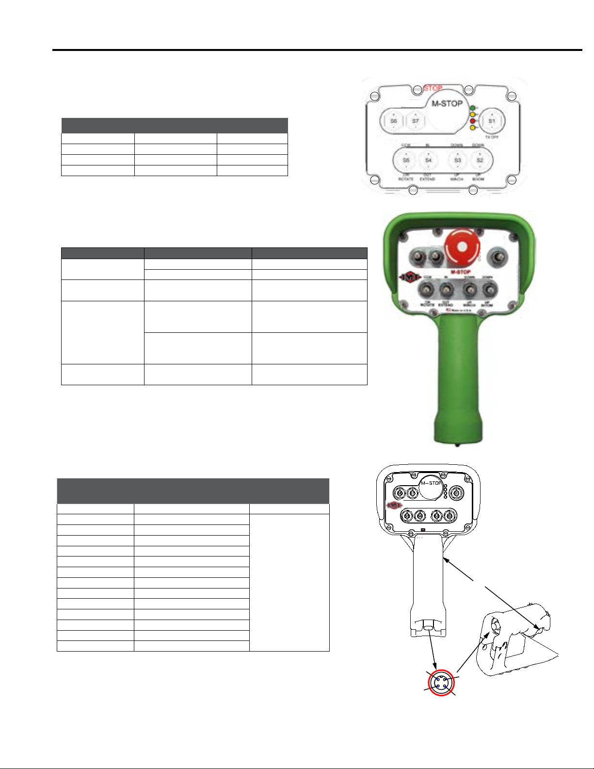
70735257- SII Radio Remote (Handheld) Transmitter - Electric Crane
LEDs
LED 1 TX GREEN
LED 2 RX AMBER
LED 3 ERR RED
LED 4 BATT AMBER
LED ACTION INDICATIONS
TX TRANSMIT
GREEN LED 1
STEADY LIT SWITCH ACTIVE
BLINK TRANSMITTING
RX RECEIVER
AMBER LED 2 BLINK RECEIVING
ERR (ERROR)
RED LED 3
STEADY LIT WHEN
STOP IS PUSHED IN OR
RELEASED
STUCK SWITCH, CON-
TACT IMT TECHNICAL
SUPPORT
FLASHING WHILE STOP
IS RELEASED (UNIT
TURNED ON)
SWITCH CONFLICT;
SWITCH IS BEING HELD
BY THE USER
BATT (BATTERY)
AMBER LED 4 CYCLE ON / OFF CHANGE BATTERIES
SWITCH
LOCATION LABEL SWITCH STYLE
STOP MACHINE STOP MAINTAINED
TRIGGER (NONE)
MOMENTARY
SW7 CONFIGURATION
SW6 NOT USED
SW1 UP TX ON
SW1 DOWN TX OFF
SW2 UP BOOM DOWN
SW2 DOWN BOOM UP
SW3 UP WINCH DOWN
SW3 DOWN WINCH UP
SW4 UP EXTEND IN
SW4 DOWN EXTEND OUT
SW5 UP ROTATE CCW
SW5 DOWN ROTATE CW
assoc
TX ON
TX OFF
store
AIR OFF
WSMB-11002
70735257
ASSOC
TX
RX
ER
BA
4
1
3
2
POWER
CAN H
COMMON
CAN L
+12VDC
TX
RX
ER
BA
CW
CCW
OUT
IN
UP
DOWN
UP
DOWN
ASSOC TX ON
STOP
assoc
70735257
TX OFF
ROTATE EXTEND BOOMWINCH
Made in U.S.A.
store
WSMB-11002
TRIGGER
assoc TX ON
assoc
store
06/15/2022
SII Telescopic Proportional Electric Crane Radio Remote

70735257 SII Handheld Remote 7 Section - 3
Pistol Grip (Handheld) Remote Special Considerations
• Inactivity timeout is ten (10) minutes
• Pistol grip input power for non-RF mode is +12VDC.
• Function switch must be engaged before the proportional trigger can be used.
Power Up the Pistol Grip (Handheld) Remote
To activate (turn on) the pistol grip remote, twist the STOP button UP (clockwise) and then hold S1 UP until the
LEDs ash and the TX begins to rapidly blink (approximately one-second). Release S1. Normal system operation
is indicated by LEDs TX and RX rapidly blinking.
Associate Mode
The pistol grip (handheld) remote (70735257) allows 1-to-1 association to a receiver base unit (70735258). To
associate there must be a clear line of sight between the handheld and the base, and both units must be OFF
(powered down). Association cannot occur while in non-RF mode. The pistol grip remote is powered down by
depressing the oversized mushroom-style STOP button or by actuating S1 DOWN. The base unit is powered
down by removing P1 and P2 connectors, or by removing the source power from the unit.
***DO NOT OPERATE THE TRIGGER WHILE ASSOCIATING***
1. Stand near the Base Unit ( in line of sight)
2. Twist the MACHINE STOP button clockwise to the UP
position.
3. Hold simultaneously switches S1 UP and S7 UP
4. All four (4) LEDs will light. When all but the TX go out
and is blinking, continue to hold S1 UP and S7 UP.
5. Power up the Base Unit.
6. Release S1 and S7.
Handheld and Base Unit association is complete when TX
and RX continue to blink (icker) when the switches are
released.
S7 S1
assoc
TX ON
TX OFF
LOW store
AIR OFF
WSMB-11002
70735257
assoc
TX
RX
ER
BA
06/15/2022
SII Telescopic Proportional Electric Crane Radio Remote

70735257 SII Handheld Remote 8 Section - 3
MIN / MAX Adjustment Fundamentals
Before performing dynamic MIN and MAX adjustments, make sure that the area around the controlled machine is
safe to operate.
• Power the Base Unit for dynamic adjustment.
• Ensure that the Base Unit LEDs and displays are close enough to be easily read.
• Adjust Mode time-out defaults to a ten-second window of opportunity where the unit returns to normal operating
mode if none of the switches are operated within the ten-second window. The timer resets to 10 seconds each
time a switch or the trigger is operated while in Adjustment Mode.
• Exist Adjust Mode either by:
• Pressing the STOP button
• Waiting for 20 seconds without operating any of the function switches on the unit.
• Releasing the function switch used to enter trigger adjustment.
MIN / MAX Adjustment Procedure for 70735257 & 70735258
1. Turn the controller on by twisting the red STOP button clockwise until the button releases (pops UP).
2. Move Switch S1 UP and allow it to return to center.
3. Enter Adjust Mode by rst holding switch S7 DOWN. Then, while still holding switch S7, hold switch S1 UP for
four (4) seconds. Adjust Mode is indicated when the bottom three base unit LEDs begin ashing: OUT, IN &
ERR.
LED LIGHTS
1TX
2RX
3ERR
4BATT
BASE UNIT LEDs
+V1, +V2, +V3 BASE UNIT VOLTAGE OK
1HE A LTH
2 RF TX
3 RF RX
4 CAN TX
5 CAN RX
6 OUTPUT ACTIVE
7 INPUT ACTIVE
8ERROR
assoc TX ON
assoc
store
70735260
+V1
+V2
+V3
HTH
RTX
RRX
CTX
CRX
OUT
IN
ERR
OUT
BU-2H20XF-11003
An Oshkosh Corportation Company
707352658 BU-2H20XF-11002
S1S7
S6
S5 S4 S3 S2
06/15/2022
SII Telescopic Proportional Electric Crane Radio Remote

70735257 SII Handheld Remote 9 Section - 3
4. Release switches S7 and S1
5. Operate any of the function toggles either UP or DOWN and hold it in position. Continue to hold the function
switch throughout the entire Adjustment procedure. The Base Unit LED (ERR) lights solid indicating MIN
Adjust Mode. LEDs OUT & IN go out (extinguish).
6. While observing the machine being controlled, slowly press the pistol grip trigger (proportional control) to the
point where the machine just begins to move.
7. When the desired result is achieved, move switch S7 DOWN to the STORE position. The MIN value is
stored. Base Unit LED (OUT) activates.
8. Release all switches including the trigger. The Base Unit LED (ERR) goes out, and the LED (IN) lights solid
indicating MAX Adjust Mode.
9. Engage and hold a function switch. Operate the trigger while observing the machine being controlled.
10. When the desired MAX value is achieved, move switch S7 DOWN to the STORE position. The MAX value is
stored. Base Unit LED (OUT) activates.
11. Release all switches, including the trigger. The system returns to MIN Adjust Mode.
NOTE:
Activating switch S7 down toggles between MIN and MAX while in Adjust Mode.
Exit Adjustment Mode either by:
• Releasing all switches—including the trigger—and waiting for the handheld to time-out.
• Pressing the red M-STOP button, which powers down the handheld remote.
HANDHELD REMOTE SPECIFICATIONS (70735257)
ITEM DESCRIPTION
POWER
VIN +1.6V TO +3.2VDC
BATTERIES FOUR (4) AA ALKALINE
BATTERY LIFE 100 HOURS
LOW V SHUTDOWN 1.6VDC 1.6VDC
AUTO-SHUTDOWN 10 MIN OF BUTTON INACTIVITY
ENVIRONMENT
OPERATING TEMP -20°C TO 55°C
(-4°F TO 131°F)
STORAGE TEMP -40°C TO 55°C
(-40°F TO 131°F)
HUMIDITY 0-100%
RADIO
FREQUENCY 2405-2480 MHz
RF POWER 100mW (MAX)
LICENSE NONE REQUIRED
MODULATION FREQUENCY HOPPING TECHNOLOGY
ANTENNA INTERNAL
ENCLOSE
DIMENSIONS INCH: 9.1 x 5.3 x 5.8 (230.6 x 133.9 x 146.9 mm)
TOTAL WEIGHT 3 LBS
DURABILITY HIGH IMPACT POLYMER CASE
FACEPLATE ALUMINUM OR POLYCARBONATE
LED INDICATORS
TX (GREEN) BLINKING - TRANSMITTING, NO SWITCH ACTIVITY
SOLID - TRANSMITTING, SWITCH ACTIVE
RX (AMBER) BLINKING - RECEIVING, NO OUTPUT OF INTEREST
ACTIVITY
ERR (RED) INDICATES ERROR WITH HANDHELD REMOTE
BATT (AMBER) LOW BATTERY INDICATION
CONTROL SWITCHES
TOGGLE SEVEN 3-POSITION SPRING RETURN TO CTR
TRIGGER SPRING RELEASE
MUSHROOM PROFESSIONAL STOP
06/15/2022
SII Telescopic Proportional Electric Crane Radio Remote

This page left intentionally blank
10
06/15/2022
SII Telescopic Proportional Electric Crane Radio Remote

Battery Installation 11 Section - 4
Battery Installation
Section - 4
06/15/2022
SII Telescopic Proportional Electric Crane Radio Remote

Battery Installation 12 Section - 4
SII Telscopic -
Battery Installation / Replacement
1. The handheld remote unit is powered by four-size AA alkaline batteries. When installing batteries, be sure to
observe proper polarity as marked on the inside of the compartment to avoid damaging the unit. To replace
or install batteries in the handheld:
2. Loosen the four Phillips battery compartment cover screws on the rear of the remote. Lift the cover form the
handheld.
3. Install or replace with four (4) fresh size AA alkaline batteries. Observe the proper polarity by positioning the
batteries as indicated in the battery compartment.
4. Replace the compartment cover and tighten the four (4) Phillips screws. These screws should not be over
tightened, but they must be tight enough to assure the gasket provides a proper seal
CAUTION
Observe proper polarity when
placing batteries into the cradle.
Improper battery placement can
result in excessive heat, battery
explosion, injury to the operator,
and damage to the remote.
06/15/2022
SII Telescopic Proportional Electric Crane Radio Remote

70735258 SII Base Receiver 13 Section - 5
70735258 SII Base
Receiver
Section - 5
06/15/2022
SII Telescopic Proportional Electric Crane Radio Remote
70735258 SII Base Receiver 14 Section - 5
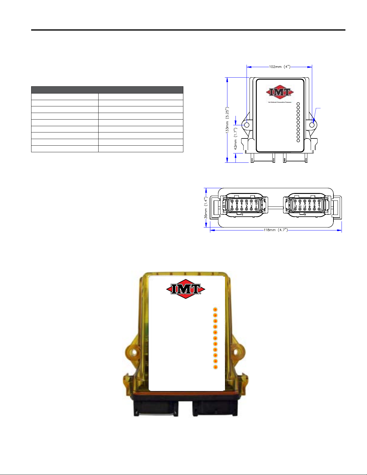
70735258 - SII Receiver Radio Remote (Base Unit) - Electric Crane
BASE UNIT LEDs
+V1, +V2, +V3 BASE UNIT VOLTAGE OK
1HE A LTH
2 RF TX
3 RF RX
4 CAN TX
5 CAN RX
6 OUPUT ACTIVE
7 INPUT ACTIVE
8ERROR
70735260
+V1
+V2
+V3
HTH
RTX
RRX
CTX
CRX
OUT
IN
ERR
OUT
BU-2H20XF-11003
An Oshkosh Corportation Company
70735258 BU-2H20XF-11002
70735258
BU-2H20XF-11002
P1 (GRAY) P2 (BLACK)
7.4mm
(.29") DIA
P1 P2
ERR
IN
OUT
CRX
CTX
RRX
RTX
HTH
+V3
+V2
+V1
70735258 WSMB-11002
06/15/2022
SII Telescopic Proportional Electric Crane Radio Remote
70735258 SII Base Receiver 15 Section - 5
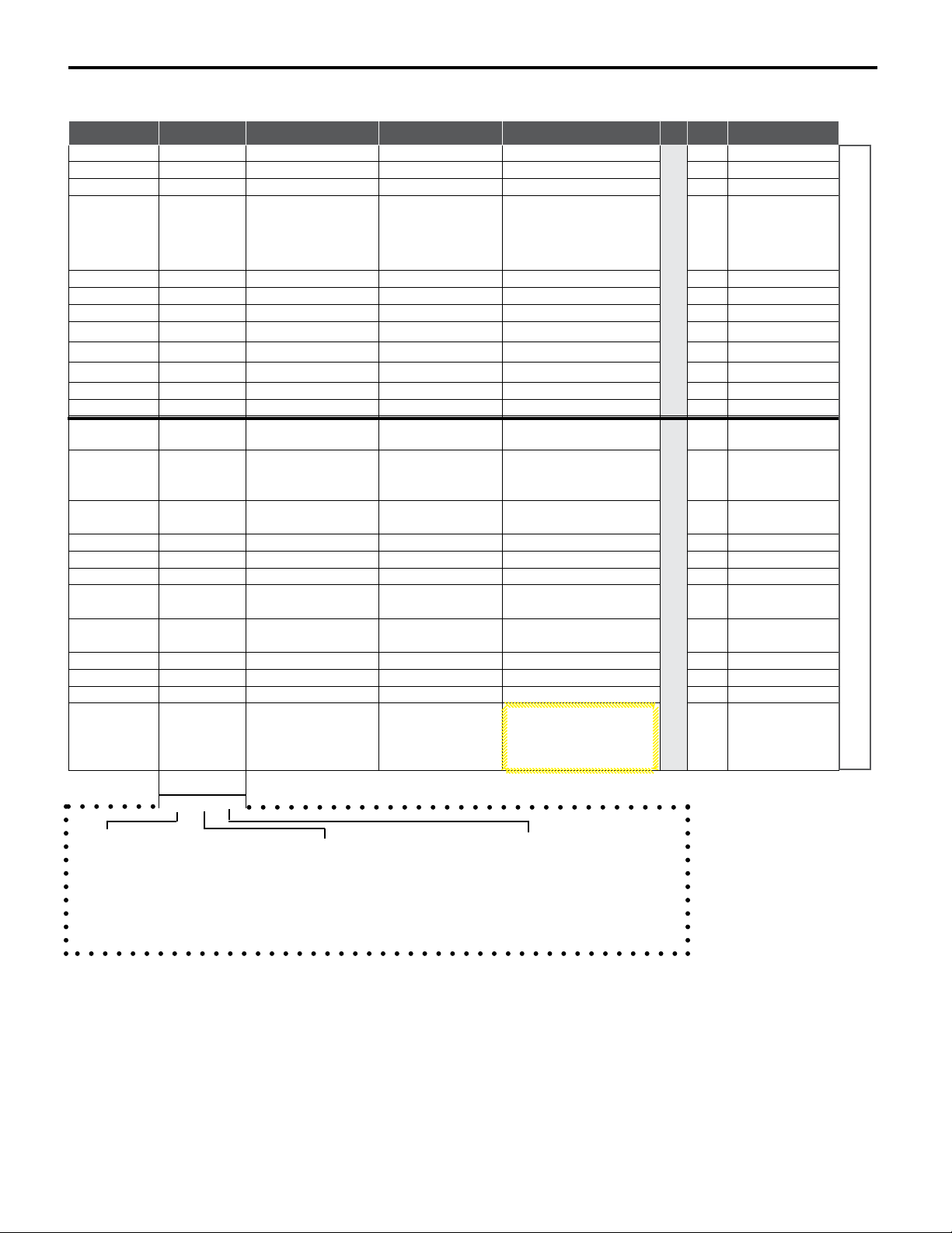
70735258 - Base Unit Conguration
CHANNEL TYPE* FUNCTION ACTIVATED BY: SETTINGS PIN WIRE
M17 NOT USED 1RED
M18 NOT USED 2ORG
-VDC 3WHT
M11 PWM PROPORTIONAL
OUPUT
S2+/- ,or S4+/-
TRIGGER +
or 5+/-
TOGGLE SWITCH
OPERATED
BEFORE TRIGGER
DEPRESSED
4GRN
M12 NOT USED 5BLU
+VDC 6RED/WHT
M13 LO-HS-M BOOM UP S2- DIGITAL 7GRN/WHT
M14 LO-HS-M BOOM DOWN S2+ +M4 DIGITAL 8BLU/WHT
M15 LO-HS-M EXTEND OUT S4- +M4 DIGITAL 9BLK/WHT
M16 LO-HS-M WINCH UP S3- +M4 DIGITAL 10 RED/GRN
M10 LO-HS-M EXTEND IN S4+ DIGITAL 11 ORG/GRN
M9 LO-HS-M WINCH DOWN S3+ DIGITAL 12 BLK
M5 LO-HS-M ROTATE
CLOCKWISE S5- DIGITAL 1RED/BLK
M6 LO-HS-M
ROTATE
COUNTER
CLOCKWISE
S5+ DIGITAL 2ORG/BLK
M7 LO-HS-M PUMP S2 +/- , or S4 +/- ,
or S5 +/- DIGITAL 3WHT/BLK
M8 NOT USED DIGITAL 4GRN/BLK
M19 NOT USED DIGITAL 5BLU/BLK
M20 NOT USED 6WHT/RED
CAN H TETHER CABLE
CONNECTION 7RED/WHT/BLK
CAN L TETHER CABLE
CONNECTION 8BLK/WHT/RED
M1 NOT USED 9WHT/BLK/RED
M2 NOT USED 10 BLU/RED
M3 NOT USED 11 ORG/RED
M4 LI-NA-M A2B/OVER LOAD
ACTIVE HIGH INPUT.
+12VDC = A2B/
OVERLOAD ACTIVE
NORMAL STATE
12 BLK/RED
*TYPES
XX-XX-XX
AI = ANALOG INPUT M = MOMENTARY
AO = ANALOG OUTPUT HS = HIGH SIDE LA = LATCHING
LI = LEVEL INPUT LS = LOW SIDE UN = UNLATCHING
LO = LEVEL OUTPUT NA = NOT APPLICABLE
PWM = PULSE WIDTH MOD
PLUG P1 (GRAY)
PLUG P2 (BLACK)
HN-1005 CABLE HARNESS
06/15/2022
SII Telescopic Proportional Electric Crane Radio Remote

70735258 SII Base Receiver 16 Section - 5
70735258 - Base Unit Hardware Specs / Base Unit Safety Link / Base Unit
Hardware
BASE UNIT HARDWARE SPECIFICATIONS
REQUIRED FIELDS DESCRIPTION DETAILS
CONTROL POWER 7-28VDC USING 12VDC
RF FREQUENCY 2400MHz 2405-2480MHz @ 100 mW
ANTENNA OPTION INTERNAL
DISCRETE CHANNELS 16 15 HIGH SIDE OUTPUTS: ONE HIGH SIDE INPUTS
PROPORTIONAL CHANNEL 1 PMW OUTPUTS
ANALOG CHANNEL 14-20mA
MESSAGE PERIODICITY 10x/s ONE MESSAGE EVERY 100ms
ON AIR TIME 2S 8 OR 16 BYTE PAYLOAD
LINK LOSS CRITERIA 0.5S 5 CONSECUTIVE MESSAGES
VALVE INFORMATION PMW FREQ: 150Hz; DUTY CYCLE: 20-80%; LOAD: 4.7Ώ
CAN INFORMATION J1939 REFER TO STANDARD EXTENDED CONFIGURATION FOR
CAN MESSAGING BETWEEN PG AND BU
BASE UNIT SAFETY LINK
WHEN ANY OF THE FOLLOWING OCCURS:
• MACHINE STOP IS PRESSED
• HANDHELD UNIT GOES OUT OF RANGE
• HANDHELD UNIT DE-ACTIVATES DUE TO LOSS OF POWER, INACTIVITY TIME-OUT, OR DELIBERATE
DEACTIVATION (OFF SWITCH)
X
ENABLED DISABLED
ALL LATCHED OUTPUTS UNLATCH, AND ALL
MOMENTARY OUTPUTS THAT ARE ACTIVE,
DE-ACTIVATE UPON ACTIVATION OF HANDHELD. NO
OUTPUTS ARE ALLOWED TO BE ACTIVATED UNTIL ALL
SWITCHES (UNLESS MASKED) ARE FIRST CENTERED
OR RETURNED TO THEIR NEUTRAL STATE.
.
ALL LATCHED OUTPUTS REMAIN LATCHED, BUT
ALL MOMENTARY COMMANDS THAT ARE ACTIVE
DE-ACTIVATE.
NOTE:
IF HANDHELD UNIT IS POWERED ON AND A
MOMENTARY COMMAND THAT WAS DE-ACTIVATED
DUE TO RANGE IS STILL ACTIVE WHEN THE HANDHELD
RETURNS IN RANGE, THE OUTPUT WILL IMMEDIATELY
BE ACTIVE AGAIN
06/15/2022
SII Telescopic Proportional Electric Crane Radio Remote
This manual suits for next models
3
Table of contents
Other IMT Construction Equipment manuals


