IMT 12916 User manual

Manual # 99905833
Model 12916 Crane
Parts & Specifications
Effective August 2014
IOWA MOLD TOOLING CO., INC.
PO Box 189
Garner, IA 50438
Tel: 641-923-3711 FAX: 641-923-2424
Website: http://www.imt.com
Copyright © 2014 Iowa Mold Tooling Co., Inc.
All rights reserved
No part of this publication may be reproduced, stored in a retrieval system, or transmitted in any
form or by any means, electronic, mechanical, photocopying, recording or otherwise without the
prior written permission of Iowa Mold Tooling Co., Inc.
Iowa Mold Tooling Co., Inc. is an Oshkosh Corporation Company.
View thousands of Crane Specifications on FreeCraneSpecs.com
View thousands of Crane Specifications on FreeCraneSpecs.com

View thousands of Crane Specifications on FreeCraneSpecs.com
View thousands of Crane Specifications on FreeCraneSpecs.com

i
Contents
Revisions .................................................................................................................................................... iii
Introduction 5
Specifications 7
Model 12916 Specifications.........................................................................................................................8
Geometric Configuration............................................................................................................................10
Minimum Chassis Specifications for 12916 Crane ....................................................................................12
Reference 13
Major Crane Assemblies ............................................................................................................................14
Weldment Part Number Locations .............................................................................................................14
Grease Zerk Locations & Lubricant Requirements ....................................................................................15
Installation..................................................................................................................................................16
Parts 19
Parts Information........................................................................................................................................20
Base & Out Assembly (40725982).............................................................................................................22
Stabilizer Cylinder (3C283801)..................................................................................................................26
Mast Assembly (40725983)........................................................................................................................27
Inner Boom Assembly (40725984) ............................................................................................................28
Inner Cylinder (3C194614).........................................................................................................................29
Outer Boom Assembly (40725985)............................................................................................................30
Outer Cylinder (3C195613)........................................................................................................................32
Extension Boom Assembly (40725986).....................................................................................................33
Extension Cylinder (51718065)..................................................................................................................34
Hydraulic Diagram, Radio Remote (99905792).........................................................................................36
Hydraulic Diagram, Radio Remote (99905792).........................................................................................38
Relief Valve Assembly, 12V Radio (73055278)........................................................................................39
Control Kit – Manual 8 Function (90704441)............................................................................................40
Valvebank Assembly – 8 Section (51706642)............................................................................................42
Valvebank Assembly – 8 Section (51706643)............................................................................................43
Hydraulic Kit – 6 Section (91703946)........................................................................................................44
Hydraulic Overload Kit, 3-Function (51717130) .......................................................................................46
Electrical Control Cabinet (41718269-12V, 41718425-24V).....................................................................48
Electrical Control Box Assembly (41718269-12V, 41718425-24V) .........................................................50
Relay Fuse Box, 12V & 24V (77044935) ..................................................................................................52
Radio Remote.............................................................................................................................................53
Installation Kit-Manual Controls (93708876) ............................................................................................54
Decal Kit (95712299).................................................................................................................................56
Capacity Alert Kit – 2800 PSI (31717169) ................................................................................................58
Capacity Shutdown Kit – 2800 PSI (31717514).........................................................................................58
Light Kit – Crane Mast Mounted (51717977)............................................................................................59
Hydraulic Shutdown Kit (31713788) .........................................................................................................61
View thousands of Crane Specifications on FreeCraneSpecs.com
View thousands of Crane Specifications on FreeCraneSpecs.com

ii 12916 Parts & Specifications Manual #99905833
Option – Hook Assembly Kit (40726070)..................................................................................................63
12916 Recommended Spare Parts List.......................................................................................................64
General Reference 65
Inspection Checklist ...................................................................................................................................65
Deficiency / Recommendation / Corrective Action Report........................................................................70
Turntable Bearing Thread Tightening Sequence........................................................................................75
Turntable Bearing Inspection .....................................................................................................................76
Thread Torque Chart (English)...................................................................................................................78
Thread Torque Chart (Metric) ....................................................................................................................79
View thousands of Crane Specifications on FreeCraneSpecs.com
View thousands of Crane Specifications on FreeCraneSpecs.com

iii
Revisions
DATE
LOCATION
DESCRIPTION
View thousands of Crane Specifications on FreeCraneSpecs.com
View thousands of Crane Specifications on FreeCraneSpecs.com

View thousands of Crane Specifications on FreeCraneSpecs.com
View thousands of Crane Specifications on FreeCraneSpecs.com

5
This volume deals with information applicable to your particular crane. For operating,
maintenance and repair instructions, refer to Volume 1, OPERATION, MAINTENANCE AND
REPAIR.
We recommend that this volume be kept in a safe place in the office.
This manual is provided to assist you with ordering parts for your IMT crane. It also contains
additional instructions regarding your particular installation.
In addition to reading the manual, it is your responsibility to become familiar with government
regulations, hazards, and the specific operation of your equipment. Use caution and common
sense while operating and maintaining the equipment and follow all safety procedures and
regulations. Treat this equipment with respect and service it regularly.
MODIFICATIONS
Modifications to your equipment must be performed with IMT approved accessories, parts and
optional equipment. If in doubt, contact IMT prior to making any modifications. DO NOT alter or
modify any safety device! All safety devices must be inspected, tested and maintained in proper
working condition.
Decals regarding safety and operation are considered safety equipment, and must be kept clean
and legible.
The equipment owner and/or designated employee is responsible for informing all operators,
maintenance personnel, and others involved in equipment operation about the safe operation
and maintenance of the equipment. If questions arise concerning safe operation, contact IMT or
your IMT distributor for clarification.
WARRANTY
Warranty of this unit will be void on any part of the unit subjected to misuse due to overloading,
abuse, lack of maintenance and unauthorized modifications. No warranty - verbal, written or
implied - other than the official, published IMT new machinery and equipment warranty will be
valid with this unit.
NOTICE TO THE OWNER / USER
If your equipment is involved in a property damage accident, contact your IMT distributor
immediately and provide them with the details of the accident and the serial number of the
equipment. If an accident involves personal injury, immediately notify your distributor and IMT
Technical Support at:
IOWA MOLD TOOLING CO., INC.
500 HWY 18 WEST
GARNER, IA 50438
641 - 923 - 3711
CHAPTER 1
Introduction
View thousands of Crane Specifications on FreeCraneSpecs.com
View thousands of Crane Specifications on FreeCraneSpecs.com

6 12916 Parts & Specifications Manual #99905833
RESPONSIBILITY
It is the user’s responsibility to maintain and operate this unit in a manner that will result in the
safest working conditions possible. In addition, it is the user’s responsibility to be aware of
existing Federal, State, and Local codes and regulations governing the safe use and
maintenance of this equipment.
MANUAL STRUCTURE
Throughout this manual, three means are used to draw the attention of personnel. They are
NOTEs, CAUTIONs and WARNINGs and are defined as follows:
CAUTION
ACAUTION is used when there is the
very strong possibility of damage to the
equipment or premature equipment
failure.
WARNING
A WARNING is used when there is the
potential for personal injury or death.
NOTE
ANOTE is used to either convey
additional information or to provide
further emphasis for a previous point.
View thousands of Crane Specifications on FreeCraneSpecs.com
View thousands of Crane Specifications on FreeCraneSpecs.com

7
In This Chapter
Model 12916 Specifications......................................................8
Geometric Configurations.........................................................10
Minimum Chassis Specifications ..............................................12
CHAPTER 2
Specifications
View thousands of Crane Specifications on FreeCraneSpecs.com
View thousands of Crane Specifications on FreeCraneSpecs.com

8 12916 Parts & Specifications Manual #99905833
Model 12916 Specifications
GENERAL SPECIFICATIONS
*CRANE RATING (ANSI B30.22)
129,000 FT-LBS
*MAXIMUM CRANE RATING
129,000 FT-LBS
HORIZONTAL REACH
from centerline of rotation
16’-2”
HYDRAULIC EXTENSION
40”
MANUAL EXTENSION
NONE
VERTICAL REACH
from mounting surface
23’-1”
VERTICAL REACH
from ground/41” frame ht.
26’-6”
CRANE WEIGHT
6,040 LBS
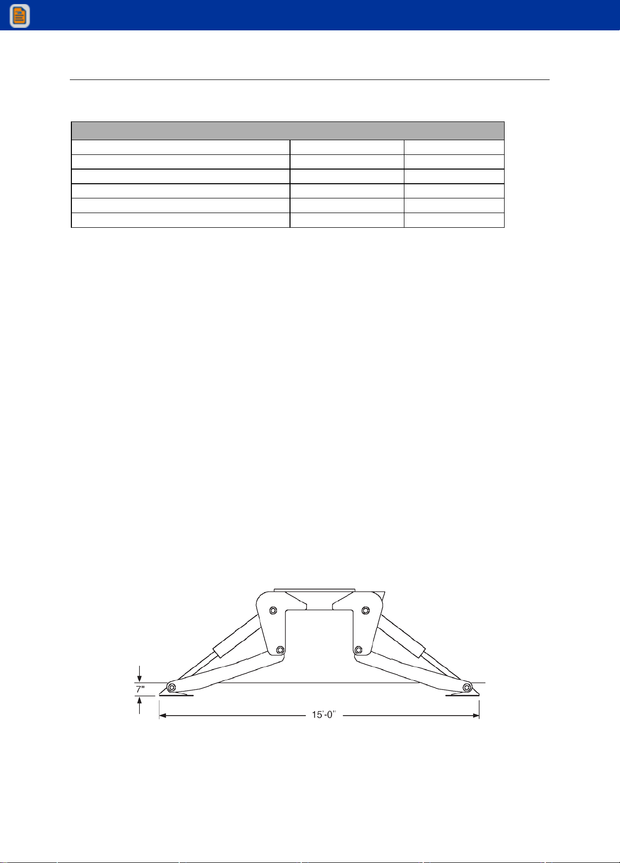
STABILIZER SPAN
15’-0”
STABILIZER PADS
12” X 19”
CRANE STORAGE HEIGHT
from mounting surface
8’-2”
CRANE STORAGE HEIGHT
from ground/41” frame ht.
11’-7”
**MOUNTING SPACE REQUIRED
32”
ROTATIONAL TORQUE
16,200 FT-LBS
OPTIMUM PUMP CAPACITY
13 U.S. GPM
SYSTEM OPERATING PRESSURE
2300 PSI
OIL RESERVOIR CAPACITY
21 U.S. GALLONS
HOOK APPROACH-HORIZONTAL
from centerline of rotation
5’-10”
HOOK APPROACH-VERTICAL
from mounting surface
9’-8”
* Maximum Crane Rating (ft-lbs) is defined as that rated load (lbs) which when multiplied by its respective distance
(ft) from centerline of rotation gives the greatest ft-lb value.
ANSI B30.22 Crane Rating (ft-lbs)= With all extensions retracted and inner plus outer boom in a horizontal position,
rated load (lbs) X respective distance (ft) from centerline of rotation = nominal ft-lb value.
** Allow an additional 3” between the cab and crane base for swing clearance.
IMT reserves the right to change specifications and design without notice. Where applicable, specifications are in
accordance with SAE standards and ISO/DIS 3691-1, the international standard for Industrial Trucks - Safety
Requirements and Verification.
IOWA MOLD TOOLING CO., INC.
BOX 189, GARNER, IA 50438-0189
TEL: 641-923-3711 FAX: 641-923-2424
View thousands of Crane Specifications on FreeCraneSpecs.com
View thousands of Crane Specifications on FreeCraneSpecs.com
Chapter 2 Specifications 9
PERFORMANCE CHARACTERISTICS
SPECIFICATIONS
SPEED
CRANE ROTATION WITH TIREHAND
370°
45 seconds
INNER BOOM ELEVATION
-23° to +67°
25 seconds
OUTER BOOM ARTICULATION
112°
19 seconds
EXTENSION BOOM
40”
6 seconds
STABILIZER EXTENSION
29-1/4”
40 seconds
POWER SOURCE
Integral-mounted hydraulic pump and PTO application. Other standard power sources may be
utilized-minimum power required is 21 horsepower.
CYLINDER HOLDING VALVES
The holding sides of all cylinders are equipped with integral-mounted holding or counter-balance
valves to prevent sudden cylinder collapse in case of hose or other hydraulic failure. The
stabilizer cylinders have positive, pilot-operated holding valves that open only on command.
The inner cylinders have single pilot-operated counter balance valves while the outer and
extension boom cylinders have double counter-balance valves. The counter-balance valve
serves several functions. First, it is a holding valve. Secondly, it is so constructed that it will
control the lowering function and allow that motion to be feathered while under load. Finally, if a
hose breaks, the only oil loss will be that in the hose.
ROTATION SYSTEM
Rotation of the crane is accomplished through a turntable bearing, powered by a high torque
hydraulic motor through a ring and pinion type spur gear train. Total gear reduction is 56.7 : 1.
HYDRAULIC SYSTEM (PTO DRIVEN)
The hydraulic system is an open-centered, full-pressure system that requires 13 GPM optimum
oil flow at 2300 PSI. Eight-spool, stack-type control valve, six of which are used for the standard
crane and the remaining two are plugged, but easily adapted for additional optional features.
Dual operational handles for six functions are located at both sides of the crane for convenient
operation. System includes hydraulic oil reservoir, suction-line strainer, pump, 8-section control
valve, return-line filter and all hoses and fittings.
STABILIZER DIMENSIONS
View thousands of Crane Specifications on FreeCraneSpecs.com
View thousands of Crane Specifications on FreeCraneSpecs.com

10 12916 Parts & Specifications Manual #99905833
Geometric Configuration
View thousands of Crane Specifications on FreeCraneSpecs.com
View thousands of Crane Specifications on FreeCraneSpecs.com

Chapter 2 Specifications 11
MODEL
CRANE
12916 EXTENSION
RETRACTED
SECONDARY
BOOM
POSITION
EXTENSION
BOOM
641-923-37 11
View thousands of Crane Specifications on FreeCraneSpecs.com
View thousands of Crane Specifications on FreeCraneSpecs.com
12 12916 Parts & Specifications Manual #99905833
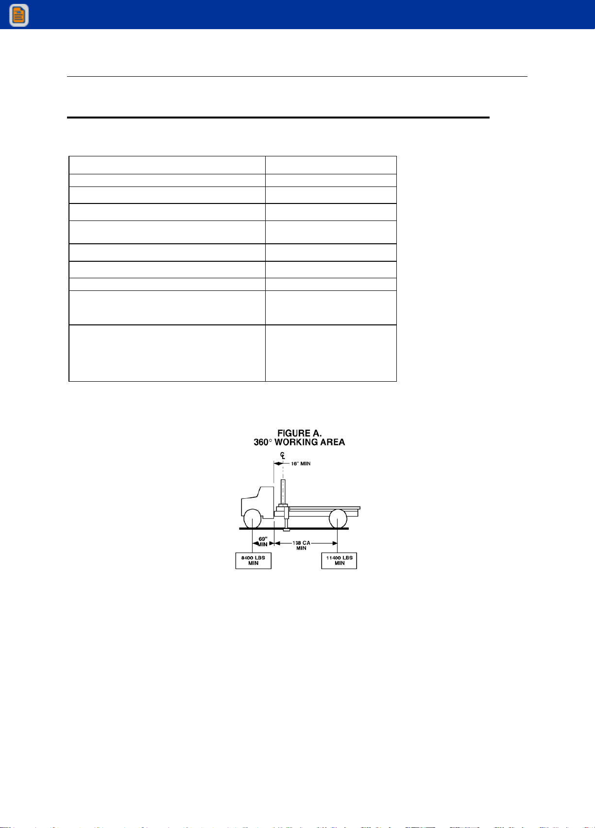
Minimum Chassis Specifications for 12916 Crane
CRANE MOUNT
Behind Cab
CRANE WORKING AREA
360°
CHASSIS STYLE
Conventional Cab
FRONT AXLE RATING (GAWR)
12,000 lbs
REAR AXLE RATING (GAWR)
Single Axle
21,000 lbs
WHEELBASE
207”
CAB-TO-AXLE
138”
OUTRIGGER WIDTH REQUIRED
15’-0”
RBM
Frame Selection Modules
Frame Yield Strength
1,664,000 in-lbs
26 cubic inches
50,000 psi
MINIMUM FINISHED UNIT WEIGHT TO
MAINTAIN VEHICLE STABILITY
Front Axle
Rear Axle
Total Finished Unit Weight
* 8,400 lbs
*11,400 lbs
19,800 lbs
*Allows lifting full capacity load in a 360° arc when crane in installed immediately behind the cab. Great
care should be taken when swinging the load from rear of vehicle to front of vehicle since the front axle
springs will compress, thus affecting the levelness of the vehicle.
NOTES:
1 GAWR means Gross Axle Weight Rating and is dependent on all components of the vehicle
such as axles, tires, wheels, springs, brakes, steering and frame strength meeting the
manufacturer’s recommendations. Always specify GAWR when purchasing a truck.
2 Minimum axle requirements may increase with use of diesel engines, longer wheelbase or
service bodies. Contact the factory for further information.
3 Weight distribution calculations are required to determine final axle loading.
4 All chassis and crane combinations must be stability tested to ensure stability per ANSI
B30.22.
View thousands of Crane Specifications on FreeCraneSpecs.com
View thousands of Crane Specifications on FreeCraneSpecs.com

13
In This Chapter
Major Crane Assemblies ..........................................................14
Weldment Part Number Locations............................................14
Grease Zerk Locations & Lubricant Requirements ...................15
Installation................................................................................16
Crane Mounting........................................................................16
Hydraulic Installation ................................................................16
CHAPTER 3
Reference
View thousands of Crane Specifications on FreeCraneSpecs.com
View thousands of Crane Specifications on FreeCraneSpecs.com
14 12916 Parts & Specifications Manual #99905833
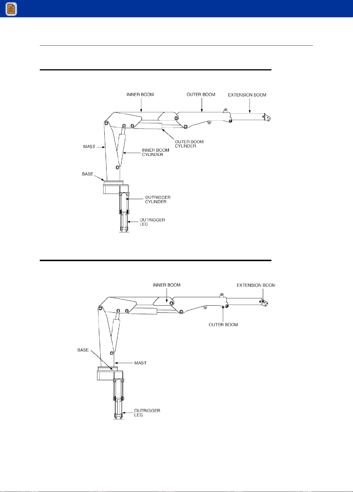
Major Crane Assemblies
Weldment Part Number Locations
View thousands of Crane Specifications on FreeCraneSpecs.com
View thousands of Crane Specifications on FreeCraneSpecs.com
Chapter 3 Reference 15
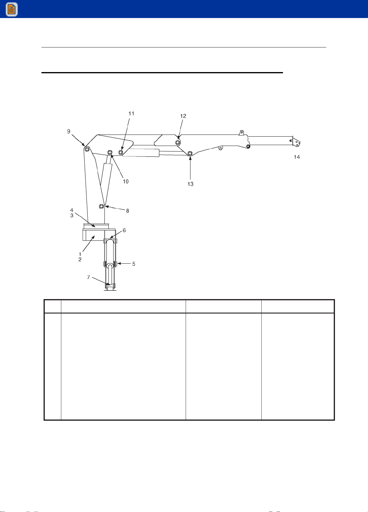
Grease Zerk Locations & Lubricant
Requirements
ITEM
LOCATION DESCRIPTION
LUBRICANT
FREQUENCY
1.
2.
3.
4.
5.
6.
7.
8.
9.
10.
11.
12.
13.
14.
TURNTABLE/BEARINGGREASEEXTENSION
*ROTATE CRANE WHILE
GREASING DRIVE GEAR
GREASE EXTENSION PINION
GEAR
PINIONCOVER
BASE/STABILIZERLEGHINGE
PIN STABILIZERCYLINDER
BASE STABILIZERCYLINDER
ROD INNER CYLINDER BASE
MAST/INNER BOOM HINGE
PIN INNER CYLINDER ROD
PIN OUTER CYLINDER BASE
INNER BOOM/OUTER BOOMHINGE
PIN OUTER CYLINDER ROD
ANY TIREHAND ATTACHMENT
SHELL ALVANIA 2EP
OR
SHELL RETINAX “A”
WEEKLY
NOTE: All application points must be greased weekly under normal workloads and moderate weather
conditions. Under severe operating conditions, lubrication should be performed more frequently. See Volume
1;Operation, Maintenanceand Repairforadditionallubricationrequirements.
View thousands of Crane Specifications on FreeCraneSpecs.com
View thousands of Crane Specifications on FreeCraneSpecs.com
16 12916 Parts & Specifications Manual #99905833
Installation
GENERAL
This section contains specific instructions for the installation of your crane. Prior to installing the
crane and hydraulic components, make sure the chassis is ready to receive the crane (refer to
Volume 1, Installation).
CRANE MOUNTING
1. See SPECIFICATIONS in Section 1 for crane weight. Using an overhead hoist and
fabric slings of adequate capacity, lift the crane about a foot to see if the crane is
adequately balanced. If not, lower hoist and adjust slings. Re-check the balance and
reposition crane until mounting surface is level.
2. Install the truck frame support so that the tie-down studs pass through the supports
(Figure below). Cut the support to the inside dimensions of the truck frame. Allow about
1/16” extra. Grind the end of the support to fit inside the frame channel. Use a hammer
to drive it into position if necessary.
3. Allow sufficient clearance between the cab and crane base, at least 3” (7.6cm). Position
the crane on the chassis per the applicable installation drawing, centering the mounting
slots over the truck frame rails. While holding crane with hoist, start mounting hardware
per Figure. Note position of support weldments on truck frame. Hand-tighten nuts.
Observe underside of crane base. No clearance between base and frame is allowed.
4. Torque the 1 1/4”-7 UNC Grade 5 mounting hardware to 840 ft-lbs (116 kg-m). When
torqueing the mounting hardware the following precautions must be followed.
a. Never use lock washers.
b. Hardened washers must be used, and under the turning element, whether the
turning element is the nut or the head of the bolt.
c. Torque values specified are with residual oils or without special lubricants applied
to the threads. If special lubricants are used, such as Never-Seize compound
graphite and oil, molybdenum disulphite colloidal copper or white lead, reduce
torque values 10%. Torque values for threaded fasteners are not affected with
the use of Loctite.
d. Do not use rusty fasteners, the rust will alter torque values significantly.
CAUTION
Do NOT attempt toapply the same torque to
the tie rod and self-locking nuts as shown in
the torque data chart. Do NOT exceed 840
ft-lb (116 kg-m). Exceeding this torque value
could damage eitherthe chassis or crane
base.
Power wrenching is notrecommended until
the lead thread of the nutinsert is engaged
by hand turning.
View thousands of Crane Specifications on FreeCraneSpecs.com
View thousands of Crane Specifications on FreeCraneSpecs.com

Chapter 3 Reference 17
5. Install the tie-plate (Figure C-1) on the truck chassis. Drill four holes using the plate as a
template and install the bolts and lock nuts. Torque the bolts to 200 ft-lbs (28 kg-m).
Weld the tie-plate to the crane base with 3/8” continuous fillet weld.
6. Install the two tension bars with nuts and washers as shown. Tighten the outside nuts
first to about 200 ft-lbs (28 kg-m) to preload the tension bar. Then tighten the inner nuts
to 466 ft-lbs (65 kg-m).
7. Touch up paint on crane and chassis as necessary.
CRANE INSTALLATION
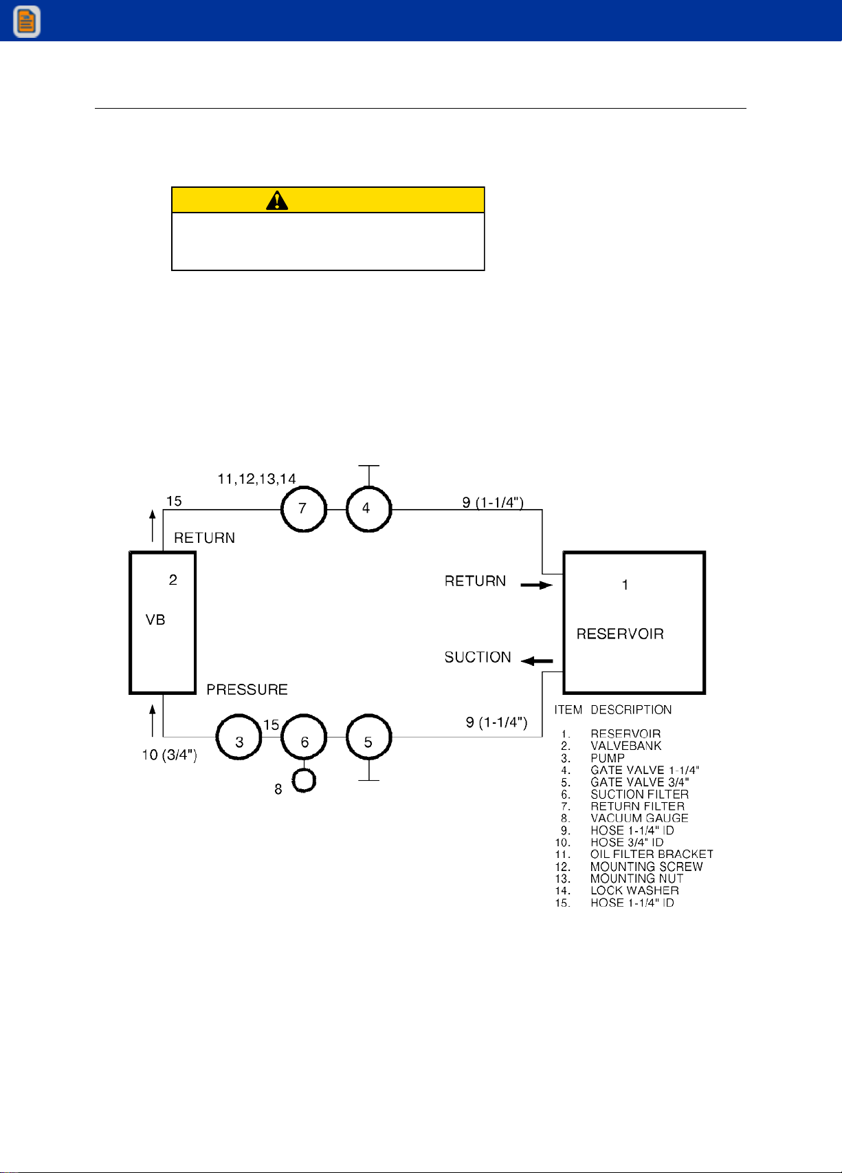
HYDRAULIC INSTALLATION
To install the hydraulic hoses, fittings, etc.:
1. Plumb the suction line filter as shown in Figure below.
2. Install the suction hose between the suction line filter and the pump inlet. Tighten the
hose clamps.
3. Install the pressure hose between the pump outlet and the inlet port on the valvebank.
4. Install the return line between the reservoir return line filter and valvebank (if
applicable).
5. Fill the hydraulic oil reservoir.
View thousands of Crane Specifications on FreeCraneSpecs.com
View thousands of Crane Specifications on FreeCraneSpecs.com
18 12916 Parts & Specifications Manual #99905833
6. Open the gate valve at the suction-line filter.
7. Open the return gate valve.
8. Start the vehicle’s engine and engage the PTO. Allow the system to run for about five
minutes and then check the vacuum gauge on the suction-line filter (it should read 8”
mercury or less). If the vacuum reading is too high, check to make certain that the
gate valve is opened completely. If the valve is fully opened, check for a collapsed or
restricted suction line.
9. Cycle all hydraulic functions. Check for leaks, and refill the reservoir if necessary.
HYDRAULIC INSTALLATION
CAUTION
Failure to open the gate valve will result in a
dry running pump which may damage the
pump.
View thousands of Crane Specifications on FreeCraneSpecs.com
View thousands of Crane Specifications on FreeCraneSpecs.com
Table of contents
Other IMT Construction Equipment manuals


Popular Construction Equipment manuals by other brands

Miller
Miller 17407 Instructions for use and maintenance

Fayat Group
Fayat Group BOMAG BW 226 DH-4 Service manual

Auto Crane
Auto Crane 4004EH owner's manual

Allstar
Allstar ALL10300 Operation manual

Altrad Belle
Altrad Belle Minimix 130 Operator's manual

Lightway
Lightway HP CRYSTAL Series Installation instruction


