IMT 5020 User manual

Printed on 27 August, 2004
Manual Part # 99901218
5020 Parts & Specifications
Effective Through July 2004
20040517
IOWA MOLD TOOLING CO., INC.
PO Box 189
Garner, IA 50438
Tel: 641-923-3711 FAX: 641-923-2424
Website: http://www.imt.com
Copyright © 2004 Iowa Mold Tooling Co., Inc.
All rights reserved
No part of this publication may be reproduced, stored in a retrieval system, or transmitted in any
form or by any means, electronic, mechanical, photocopying, recording or otherwise without the
prior written permission of Iowa Mold Tooling Co., Inc.


i
Contents
Revisions .................................................................................................................................................... iii
Introduction 5
Specifications 7
General Specifications ..................................................................................................................................7
Performance Characteristics .........................................................................................................................8
System Specifications...................................................................................................................................9
Geometric Configuration, 5020 ..................................................................................................................11
Capacity Chart, 5020 ..................................................................................................................................12
Crane Reference 13
Assemblies and Grease Zerk Locations......................................................................................................14
Recommended Spare Parts List ..................................................................................................................15
Crane Installation........................................................................................................................................17
Hydraulic Installation .................................................................................................................................19
Crane Control..............................................................................................................................................19
Parts 21
Parts Information ........................................................................................................................................22
Base and Mast Assemblies .........................................................................................................................24
Base Assembly (41714695) ........................................................................................................................25
Gear Rotator (71056543) ............................................................................................................................26
71056543 Drawing...............................................................................................................27
Mast Assembly (41714694)........................................................................................................................28
Winch / Cable / Hook Kit (31717146)........................................................................................................29
31717146 Drawings .............................................................................................................30
Winch (70570501) ......................................................................................................................................32
70570501 Drawing ..........................................................................................................................33
Boom Assemblies & Cylinders...................................................................................................................34
Boom Assembly, Lower (41717147)..........................................................................................................35
Lower Cylinder (51718547) (Eff. 6-29-04) ................................................................................................37
51718547 Drawing ..........................................................................................................................38
Cylinder, Lower (3C210010) (Thru 6-04) ..................................................................................................39
3C210010 Drawing .........................................................................................................................40
Boom Assembly, Extension (41717145) ....................................................................................................41
Boom Assembly, Extension, Flip-Sheave 20' (41714691) .........................................................................42
Cylinder, Extension, 1H 1M (3B210013)...................................................................................................44
3B210013 Drawing ..............................................................................................................44
Valve, Counterbalance (73540035) ............................................................................................................45
Hydraulics...................................................................................................................................................46
Hydraulic Kit, Tethered Remote (91715636) & Radio Remote (91715571)..............................................47
91715636 & 91715571 Drawings ........................................................................................48

ii Contents
Valvebank, Tethered Remote (73733395) ..................................................................................................51
73733395 Drawing...............................................................................................................52
Valvebank, Radio Remote (73733380).......................................................................................................53
73733380 Drawing...............................................................................................................54
Controls ......................................................................................................................................................55
Control Kit, Tethered Remote (90715437) .................................................................................................56
Cable Assembly, Tethered Remote (70733394) .........................................................................................57
70733394 Drawings .............................................................................................................57
Electrical Schematic, Tethered Remote (99900855) ..................................................................................63
99900855 Drawing...............................................................................................................64
Handle Assembly, Tethered Remote (51713182).......................................................................................65
51713182 Drawings.............................................................................................................66
Control Kit, Radio Remote (90715572)......................................................................................................68
90715572 Drawings .............................................................................................................68
Cable Assembly, Radio Remote (70733351)..............................................................................................71
70733351 Drawings .............................................................................................................72
Electrical Schematic, Radio Remote (99903131) .......................................................................................80
Handle Assembly, Radio Remote (70733354) ...........................................................................................81
70733354 Drawings .............................................................................................................81
Handle Assembly, Radio Remote Backup (51716912) ..............................................................................83
Cable Assembly, Radio Remote Backup (73733374).................................................................................85
Auxiliary Outrigger Assemblies and Valvebanks.......................................................................................86
Outrigger, Power Out/Power Down, 7x5 (31712739) ................................................................................87
Outrigger, Manual Out/Power Down, 7x5 (31712740) ..............................................................................89
Outrigger, Manual Out/Crank Down, 7x5 (31712741)...............................................................................91
Outrigger, Manual Out/Manual Down, 7x5 (31712902) ............................................................................92
Cylinder, Power Down (3B205010) ...........................................................................................................93
Cylinder, Power Out (3B142860) ...............................................................................................................94
Valve Bank, 2-Section (51714813).............................................................................................................95
Valve Bank, 3-Section (51714812).............................................................................................................96
Installation Kits...........................................................................................................................................97
Installation Kit (93715267).........................................................................................................................98
Miscellaneous .............................................................................................................................................99
Decal Kit (95717151) .................................................................................................................................99
95717151 Drawing ........................................................................................................................100
Boom Support Assembly (51714181) ......................................................................................................101
Reservoir (51707798) ...............................................................................................................................102
Cord Reel Assembly (51713168)..............................................................................................................103
Chassis Wiring Harness (99903340) ........................................................................................................104
General Reference 105
Inspection Checklist..................................................................................................................................106
Deficiency / Recommendation / Corrective Action Report ......................................................................110
Wire Rope Inspection ...............................................................................................................................112
Hook Inspection........................................................................................................................................113
Holding Valve Inspection .........................................................................................................................114
Anti-Two-Block Device Inspection..........................................................................................................114
Thread Torques.........................................................................................................................................115
Turntable Bearing Thread Tightening Sequence ......................................................................................118
Turntable Bearing Inspection for Replacement ........................................................................................119
Turntable Bearing Tilt Test.......................................................................................................................119

Contents iii
Revisions
DATE LOCATION DESCRIPTION
20040325 New Manual New release of 5020 manual.
20040517 51718547 New lower cylinder, revised cylinder part number is boom assembly
drawings.


5
This volume deals with information applicable to your particular crane. For operating,
maintenance and repair instructions, refer to Telescopic Crane Volume 1: OPERATION,
MAINTENANCE AND REPAIR. (IMT part number 99903514.)
We recommend that this volume be kept in a safe place in the office.
This manual is provided to assist you with ordering parts for your IMT crane. It also contains
additional instructions regarding your particular installation.
It is the user’s responsibility to maintain and operate this unit in a manner that will result in the
safest working conditions possible.
Warranty of this unit will be void on any part of the unit subjected to misuse due to overloading,
abuse, lack of maintenance and unauthorized modifications. No warranty - verbal, written or
implied - other than the official, published IMT new machinery and equipment warranty will be
valid with this unit. In addition, it is also the user’s responsibility to be aware of existing Federal,
State and Local codes and regulations governing the safe use and maintenance of this unit. This
crane was designed and built to meet the standards of ANSI/ASME B30.5, Mobile & Locomotive
Cranes. Contact the American Society of Mechanical Engineers (www.asme.org) for more
information.
Throughout this manual, three means are used to draw the attention of personnel. They are
NOTE’s, CAUTION’s and WARNING’s and are defined as follows:
NOTE
A NOTE is used to either convey additional information or to provide further emphasis for a
previous point.
CAUTION
A CAUTION is used when there is the very strong possibility of damage to the equipment or
premature equipment failure.
WARNING
A WARNING is used when there is the potential for personal injury or death.
For a safe work environment, treat this equipment with respect and service it regularly.
CHAPTER 1
Introduction


7
In This Chapter
General Specifications .............................................. 7
Performance Characteristics ..................................... 8
System Specifications ............................................... 9
Geometric Configuration, 5020 ................................. 11
Capacity Chart, 5020................................................. 12
General Specifications
GENERAL SPECIFICATIONS
CRANE RATING * 50,000 ft-lb (6.92 ton-meters)
REACH (from centerline of rotation) 20'-0" (6.10 m)
HYDRAULIC EXTENSIONS (2) 60" (152.4 cm)
MANUAL EXTENSION 48" (121.9 cm)
LIFTING HEIGHT (from base of crane) 21'-11" (6.68 m)
CRANE WEIGHT 1625 lb (737 kg)
OUTRIGGER SPAN (required option)
- Crane Side from Centerline of Chassis
- Opposite Crane Side from Centerline of
Chassis
90" (228.6 cm)
48" (121.9 cm)
STORAGE HEIGHT (crane only) 35" (88.9 cm)
MOUNTING SPACE REQUIRED (crane
base)
20" x 21" (50.8 cm x 53.3 cm)
OPTIMUM PUMP CAPACITY (PTO
Driven)
10 U.S. GPM (38.8 liters/minute)
SYSTEM OPERATING PRESSURE 3000 psi (207 bar)
LOWER BOOM CYLINDER 4-1/2" bore; 22-1/2" stroke (11.4 cm bore; 57.29 cm
stroke)
EXTENSION BOOM CYLINDER 2-1/2" bore; 60" stroke (6.4 cm bore; 152.4 cm
stroke)
HORIZONTAL CENTER OF GRAVITY
(from centerline of rotation)
36.25" (96.5 cm)
VERTICAL CENTER OF GRAVITY (from
bottom of crane base)
21" (50.8 cm)
TIE-DOWN BOLT PATTERN (on center) 14-3/4" x 14-3/4" (37.5 cm x 37.5 cm)
ROTATIONAL TORQUE 9000 ft-lb (1.2 ton-m)
CHAPTER 2
Specifications

8 5020 Parts & Specifications Manual Part # 99901218
* Crane rating (ft-lb) is the rated load (lb) multiplied by the respective distance (ft) from centerline
of rotation with all extensions retracted and lower boom in horizontal position.
Performance Characteristics
SPECIFICATION PTO
ROTATION 400° (7.0 rad) 33 seconds
LOWER BOOM ELEVATION -10° to +80° (-0.17 to +1.4 rad) 11.5 seconds
EXTENSION CYLINDER 60" (152.4 cm) 9.5 seconds

Chapter 2 Specifications 9
System Specifications
POWER SOURCE
PTO DRIVEN - Integral mounted hydraulic pump and PTO application. Other standard power
sources may be used. Minimum power required is 23.5 horsepower based on 10 GPM (37.9
liters/min) at 3,000 PSI (207 bar).
CYLINDER HOLDING VALVES
The base ends (extend sides) of the lower boom and extension cylinders are equipped with
integral-mounted counterbalance valves to prevent sudden cylinder collapse in case of hose or
other hydraulic failure. The extend side of the lower boom cylinder is equipped with a 10 gpm
counterbalance valve. The counterbalance valve serves several functions. First, it is a holding
valve. Secondly, it is designed to control the speed at which the lowering function operates, and
allows that motion to be metered under load. Finally, it prevents the loss of an excess amount of
oil in the event of a hose failure. Only the oil in the hose, at the time of the failure, will be lost.
ROTATION SYSTEM
Turntable bearing with external worm gear powered with a high-torque hydraulic motor through a
self-locking worm. Total gear reduction is 85 to 1.
HYDRAULIC SYSTEM (PTO DRIVEN)
The hydraulic system is an open-centered, full-pressure system that requires 10 GPM (37.85
liters/min.) optimum oil flow at 3000 psi (207 bar). It is equipped with a four-section, stack-type,
electric, remote control valve with 30-foot control cable. The system includes a separate
hydraulic oil reservoir, suction line filter, and return-line filter.
EXCESSIVE LOAD LIMIT SYSTEM (ELLS)
Overloading of the crane is limited by the ELLS system. The system consists of a pressure
switch which is mounted on the extend side of the lower boom cylinder and connected
electrically to the lift side of the winch, the extend side of the extension boom, and the down side
of the lower boom. If the operator attempts to lift a load exceeding the rated capacity of the
crane, the winch lift, extension out and lower boom down functions will not operate. To relieve
the situation, the operator may set the load down (winch down) or retract the extension boom
(extension in).

10 5020 Parts & Specifications Manual Part # 99901218
WINCH
The winch is powered using a hydraulic motor driving a 38:1 worm gear. The line speed of 25.0
ft/minute (7.62 m/min), under no load on the first wrap, is achieved at an optimum oil flow of 10
GPM (37.9 liters/min) and one-part line. Maximum single line lifting capacity of the winch is
4300 lb (1950 kg) on the top wrap. Maximum two-part line lifting capacity of the winch is 8500 lb
(3400 kg). The winch is equipped with 85 feet (25.9 m), 3/8" (9.5 mm), 6X25 FW PRF RRL
IWRC XIPS wire rope. Nylon sheaves are located at the tip of the extension boom. The ratio of
winch drum and sheave pitch diameter is 18.6:1 for the drum and 18:1 for the snatch block and
boom tip sheave. A compact anti-two block device is included to prevent the lower block or hook
assembly from coming in contact with the boom sheave assembly.
MINIMUM CHASSIS SPECIFICATIONS
CHASSIS STYLE Conventional Cab
WHEELBASE 154" (391 cm)
CAB-TO-AXLE 84" (213 cm)
RESISTANCE TO BENDING
MOMENT
600,000 in-lb (6915 kg-
m)
FRAME SECTION
MODULUS
12 cubic inches (196.7
cc)
FRONT AXLE RATING
(GAWR)
7,000 lb (3175 kg)
REAR AXLE RATING
(GAWR)
15,000 lb (6804 kg)
GROSS VEHICLE RATING 22,000 lb (9979 kg)
TRANSMISSION 5 speed
In addition to these specifications, heavy duty electrical and cooling systems are required. It is
recommended that the vehicle be equipped with an engine tachometer, auxiliary brake lock, and
power steering.
NOTES:
1 GAWR means Gross Axle Weight Rating. GAWR is dependent on all vehicle components
including axles, tires, wheels, springs, brakes, steering and frame strength meeting the
manufacturer's recommendations. Always specify GAWR when purchasing a truck.
2 Minimum axle requirements may increase with use of diesel engines, longer wheelbase or
service bodies. Contact the factory for more information.
3 Weight distribution calculations are required to determine final axle loading.
All chassis, crane and body combinations must be stability-tested to ensure stability per ANSI
B30.5
Iowa Mold Tooling Co., Inc. reserves the right to change specifications and design without notice.
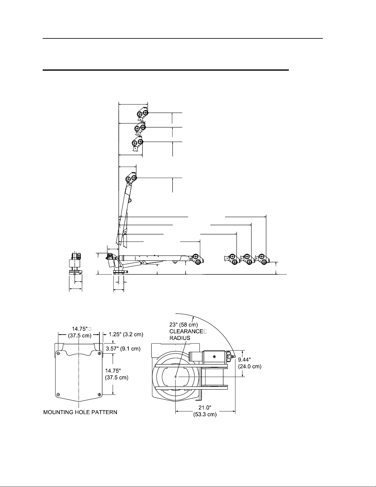
Chapter 2 Specifications 11
Geometric Configuration, 5020
20.8"
(52.9 cm)
12.0"
(30.2 cm)
16.7"
(42.4 cm)
8.37" (21.3 cm)
35.0"
(88.9 cm)
18.61"
(47.3 cm)
17.0" (43.2 cm) 22.0" (55.9 cm) 20.0" (50.8 cm)
13'-1"
(3.99 m)
18'-0"
(5.49 m)
20'-0"
(6.10 m)
21'-11"
(6.68 m)
20'-1" (6.12 m)
18'-1" (5.51 m)
16'-1" (4.90 m)
11'-1" (3.38 m)
3'-11"
(1.19 m)
3'-7"
(1.09 m)
3'-3"
(1.0 m)
2'-5"
(0.74 m)
12 5020 Parts & Specifications Manual Part # 99901218
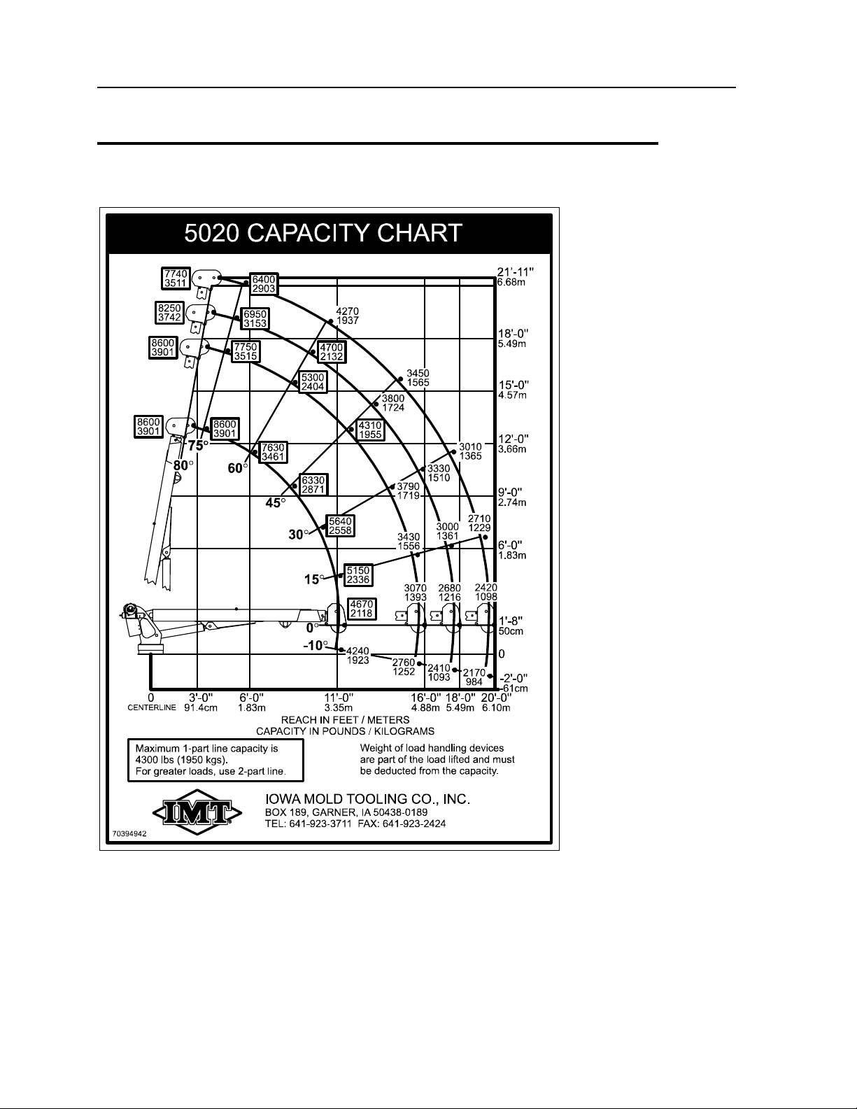
Capacity Chart, 5020

13
In This Chapter
Assemblies and Grease Zerk Locations.................... 14
Recommended Spare Parts List ............................... 15
Crane Installation ...................................................... 17
Hydraulic Installation ................................................. 19
Crane Control ............................................................ 19
CHAPTER 3
Crane Reference
14 5020 Parts & Specifications Manual Part # 99901218
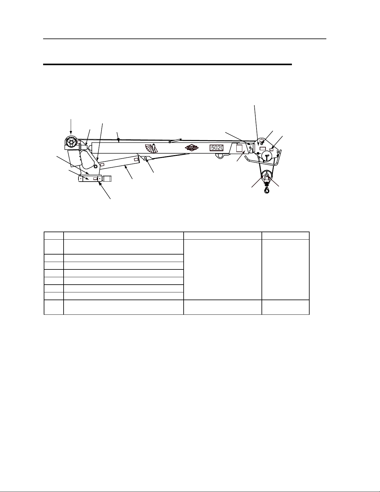
Assemblies and Grease Zerk Locations
WINCH
LOWER BOOM
EXTENSION BOOM
W/INTERNAL HYDRAULIC
EXTENSION CYLINDER
EXTENSION BOOM
(MANUAL)
5 (OTHER
SIDE)
6 (OTHER
SIDE)
7SNATCH
BLOCK
LOWER
BOOM
LOWER
CYLINDER
3
8
1
BASE
MAST
4
2
NOTE: Assemblies and part number locations are identified by name; grease zerks are identified
by number.
ITEM LOCATION DESCRIPTION LUBRICANT FREQUENCY
1. Gear Rotator Grease Extension
*Rotate Crane While Greasing.
2. Lower Cylinder Base
3. Lower Cylinder Rod
4. Mast/Lower Boom Hinge Pin
5. Upper Sheave Pin
6. Lower Sheave Pin
7. Snatch Block Sheave Pin
Shell Alvania 2EP
or
Shell Retinax "A"
Weekly
8. Worm Drive Bearings
*3 Pumps/ Then Rotate Crane Fully
Extreme Pressure EP2
Grease
Every 3 months
NOTE: All application points must be greased weekly under normal work loads and moderate
weather conditions. Under severe operating conditions, lubrication should be performed more
frequently. See Volume 1: Telescopic Crane Operation & Safety (99903514) for additional
lubrication requirements.

Chapter 3 Crane Reference 15
Recommended Spare Parts List
This spare parts list does not necessarily indicate that the items can be expected to fail in the
course of a year. It is intended to provide the user with a stock of parts sufficient to keep the unit
operating with the minimal down-time waiting for parts. There may be parts failures not covered
by this list. Parts not listed are considered as not being Critical or Normal Wear items during the
first year of operations and you need to contact the distributor or manufacturer for availability.
ASSEMBLY DESCRIPTION
IMT PART # NAME QUANTITY
BASE ASSEMBLY (41714695)
73051919 HYDRAULIC MOTOR 1
LOWER BOOM ASSEMBLY (41717147)
3C210010 LOWER CYLINDER 1
60120124 WEAR PAD 4
72060293 CAP SCREW 5/16-24X1
HHGR5
8
LOWER CYLINDER (3C210010)
4G035980 ROD ASSEMBLY 1
6HD45022 HEAD 1
6ID45143 PISTON 1
9D181823 SEAL KIT 1
77041561 PRESSURE SWITCH 1
73540052 COUNTERBALANCE VALVE 1
EXTENSION BOOM ASSEMBLY (41717145)
3B210013 EXTENSION CYLINDER 1
60030189 WEAR PAD 1
60030134 SHEAVE 2
EXTENSION BOOM ASSEMBLY, 20' WITH
FLIPSHEAVE (41714691)
3B313960 EXTENSION CYLINDER 1
60030189 WEAR PAD 1
EXTENSION CYLINDER (3B210013)
73054999 COUNTERBALANCE VALVE 1
9D101220 SEAL KIT 1
WINCH / CABLE / HOOK KIT (31714696) & WINCH /
CABLE / HOOK KIT W/ FLIPSHEAVE (31714697)
73051940 HYDRAULIC MOTOR 1
70580143 CABLE ASSEMBLY 1

16 5020 Parts & Specifications Manual Part # 99901218
51713168 CORD REEL 1
77041291 SWITCH 1
52709413 CABLE 1
60030108 ROLLER-CABLE GUIDE 1
60030134 SHEAVE 1
71073035 HOOK 1
70074004 HOOK SAFETY LATCH 1
WINCH ASSEMBLY (70570501)
76393174 O-RING 1
76393173 OIL SEAL 1
70055202 BALL BEARING 2
70733294 BRAKE KIT 1
76393171 GASKET 2
PROPORTIONAL REMOTE HANDLE ASSEMBLY
(51713182)
51713182 PROP. REMOTE HANDLE
ASSEMBLY
1
70394183 TRIGGER ASSEMBLY 1
77040371 TOGGLE SWITCH SPST 1
77040372 TOGGEL SWITCH SPDT 2
77040373 TOGGLE SWITCH SPST 1
77040374 TOGGLE SWITCH SPDT 1
INSTALLATION KIT (93715267)
73052006 FILTER ELEMENT, 10 MIC 2
GEAR ROTATOR (71056543)
70395074 O-RING 1
70395076 SEAL 1
70145786 SNAP RING 1
70055271 BEARING - CONE 2
70055281 BEARING - CUP 2
70145501 BEARING RETAINER 1
70056550 WORM 1
73145506 SHIM 0.005 2
73145505 SHIM 0.015 2
73145504 SHIM 0.030 2
76395075 GASKET 1

Chapter 3 Crane Reference 17
Crane Installation
GENERAL
This section contains instructions for the installation of your crane. Prior to installing the crane
and hydraulic components, make sure that the chassis is ready to receive the crane (see the
Installation Section of the IMT Telescopic Crane Operation & Safety Manual, 99903514).
Reinforce the chassis frame, as necessary, and install the PTO and pump.
Each installation may vary in components used. It is important to use hoses of proper length,
pumps of correct size, and PTO’s of adequate speed. Study the applicable installation kit in the
parts section before attempting any installation.
CRANE INSTALLATION
In addition to meeting Minimum Chassis Specifications, there must be sufficient room for
mounting the crane and the platform must be strong enough to support the crane and rated load.
Install the 5020 crane only on an IMT designed and approved truck body. The body must be
designed to sustain the forces imposed by the crane when lifting the full rated load. In addition,
an IMT designed body is designed to take full advantage of the standard reservoir placement.
This reservoir is installed in the cargo area of the body. Before attempting to install the crane,
the body must be installed.
To install the crane:
1 Use a lifting device capable of lifting the weight of the crane, up to 1625 lb (737 kg). Attach
fabric slings to the crane lower boom, centered approximately 18 inches from the mast hinge.
Make certain the crane is well balanced on the slings by slowly lifting approximately 6" off the
ground. Lift the crane, apply a bead of waterproof compound, such as silicon based caulk, to
the bottom of the base. Move the chassis under the crane and lower the crane into the
desired position.
2 Install the 1-8x3" mounting cap screws and 1" washers to secure the crane base to the truck
body (see figure). Torque the cap screws to 680 ft-lb (94 kg-m).

18 5020 Parts & Specifications Manual Part # 99901218
CAUTION
THE 3" BOLTS SUPPLIED ARE FOR USE ON BODIES WITH A CRANE BOX TOP PLATE
THICKNESS OF 7/8" TO 1" ONLY. DETERMINE THE CRANE BOX TOP PLATE
THICKNESS PRIOR TO MOUNTING. IF DIFFERENT LENGTH BOLTS ARE REQUIRED,
THEY MUST BE 1-8, GRADE 8, ZINC COATED, OF THE PROPER LENGTH. FAILURE TO
USE PROPER LENGTH BOLTS MAY CAUSE THE BOLTS UNDER THE WORM HOUSING
TO BOTTOM OUT BEFORE TORQUEING. INSURE A MINIMUM OF 1-1/2" THREAD
ENGAGEMENT.
W
ASHER 1"
(4 PLACES)
CAP SCREW
1-8X3" GR8
(4 PLACES)
14.75"
(37.5 cm) 1.25" (3.2 cm)
3.57" (9.1 cm)
14.75"
(37.5 cm)
MOUNTING HOLE PATTERN
Table of contents
Other IMT Construction Equipment manuals


Popular Construction Equipment manuals by other brands

ACO
ACO SERVOKAT GD Installation and maintenance manual

Greenlee
Greenlee 555 Series instruction manual

Altrad
Altrad Belle BGN+ Operator's manual

Rosco
Rosco Maximizer 2B Operation, service & parts manual

Manitowoc
Manitowoc Grove GRT8100 Service manual

Beta Max
Beta Max MAXIAL TRACK HOIST Use and maintenance instruction manual

Festool
Festool CT-VA Original operating instructions

SET MAKINA
SET MAKINA TIGERFILL Maintenance and Instruction Manual

Scheppach
Scheppach PM1800D Original instruction manual

stellar labs
stellar labs 10621 owner's manual

Kato
Kato PREMIUM CITYRANGE CR-200RF instruction manual

SIXTY82
SIXTY82 M29S LENGTH 300 Original user manual


