IMT Telescopic III Series User manual

IOWA MOLD TOOLING CO., INC.
P.O. Box 189
Garner, IA 50438
Tel: 641.923.3711
Fax: 641.923.2424
www.imt.com
Series III Telescopic
10000 25-Foot
Parts & Specifications
Manual # 99905184
Revised: April 22, 2019
Copyright © 2019 Iowa Mold Tooling Co., Inc.
All rights reserved
No part of this publication may be reproduced, stored in a retrieval system, or transmitted in any form
or by any means, electronic, mechanical, photocopying, recording or otherwise without the prior written
permission of Iowa Mold Tooling Co., Inc.
Iowa Mold Tooling Co., Inc. is an Oshkosh Corporation Company

ii
Series III Telescopic - Manual # 99905184

iii
Series III Telescopic - Manual # 99905184
Table of Contents
Introduction 1
Personal Fall/Tie-O Protection .....................................................................................................................3
Specications 5
10000 25’ - Specications..............................................................................................................................6
10000 25’ - Dimensional Drawings ................................................................................................................8
10000 25’ - Crane Capacity Load Chart.........................................................................................................9
Crane Reference 11
10000 25’ - Greasing Instructions ................................................................................................................12
10000 25’ - Greasing Locations ...................................................................................................................13
10000 25’ - Crane Recommended Spare Parts List ....................................................................................14
10000 25’ - Installation Introduction .............................................................................................................15
10000 25’ - Crane Installation Kit (99905067)..............................................................................................16
10000 25’ - Chassis Wiring Harness (77441476 / 99905212) .....................................................................19
10000 25’ - Telescopic Crane Orientation....................................................................................................20
SIII Telescopic Fully Proportional Radio Remote System............................................................................21
SIII Telescopic Single Proportional Radio Remote System .........................................................................22
Parts 23
10000 25’ - Parts Information.......................................................................................................................24
10000 25’ - Crane Assembly Test Stand Mount ...........................................................................................26
10000 25’ - Crane Assembly Truck Mount ..................................................................................................28
10000 25’ - Boom Assembly .......................................................................................................................30
10000 25’ - Fully Proportional Valve Bank Assembly (99906280) .............................................................. 32
10000 25’ - Single Proportional Valve Bank Assembly (99906279).............................................................34
10000 25’ - Winch & Anti-Two Block Assemly..............................................................................................36
10000 25’ - Crane & Winch Assembly .........................................................................................................38
10000 25’ - Flip Sheave & Snatch Block Assembly ....................................................................................40
10000 25’ - Gear Rotator, Primary ..............................................................................................................42
10000 25’ - Lower Cylinder (51722956).......................................................................................................44
10000 25’ - Extension Cylinder (51723605).................................................................................................46
10000 25’ - Winch Oil Specications............................................................................................................49
10000 25’ - Winch Parts - 6000 LB Line Pull (70570771)............................................................................50
10000 25’ - Valve Bank, Fully Proportional (73734727)...............................................................................52
10000 25’ - Valve Bank, Single Proportional (73734472) ............................................................................54
10000 25’ - Connection Block Seal Kit For 73734727 (94399213)..............................................................56
10000 25’ - Seal Kit for 73734727 (94399214) ............................................................................................ 58
10000 25’ - Plumbing Diagram, Fully Proportional (99905028) ...................................................................60
10000 25’ - Plumbing Diagram, Single Proportional (99906029).................................................................64
Electrical & Lighting 67
10000 25’ - Boom Tip LED Light Kit (99905289)..........................................................................................68
10000 25’ - Radio Remote Harness (77441481) .........................................................................................70
10000 25’ - Radio Remote Harness (77441481-1) ......................................................................................71
10000 25’ - Radio Remote Harness (77441537) .........................................................................................72
10000 25’ - Radio Remote Harness (77441537-1) ......................................................................................73
General Information 75
10000 25’ - Decal Placement.......................................................................................................................76
10000 25’ - Thread Torque Charts ...............................................................................................................78

This page left intentionally blank
iv
Series III Telescopic - Manual # 99905184
10000 25’ - Thread Torque Chart - Metric ....................................................................................................79
10000 25’ - Turntable Bearing Thread Tightening Sequence.......................................................................80

Section - 1 1 Introduction
Series III Telescopic - Manual # 99905184
Section - 1Introduction

Section - 1 2 Introduction
Series III Telescopic - Manual # 99905184
INTRODUCTION
This volume includes specications, installation information, and spare parts drawings applicable to your particular
crane. For operating, maintenance and repair instructions, see Telescopic Crane Operation, Maintenance, and
Repair Manual (IMT part number 99905190).
It is your responsibility to operate and maintain this unit in a manner that will result in the safest working conditions
possible. You must be aware of existing Federal, State and Local codes and regulations governing the safe use
and maintenance of this IMT crane. The crane was designed and built to meet the standards of ANSI/ASME
B30.5, Mobile & Locomotive Cranes. Contact the American Society of Mechanical Engineers (www.asme.org) for
more information on ANSI/ASME B30.5.
Misuse of the crane through overloading, abuse, lack of maintenance and unauthorized modications will void the
warranty on any part of the unit subjected to this misuse. No warranty–verbal, written or implied–other than the
ocial, published IMT new machinery and equipment warranty will be valid with this unit.
Throughout the manual, NOTE, CAUTION, and WARNING are used to draw the attention of personnel. They are
dened as follows:
WARNING
A WARNING is used when there is the potential
for personal injury or death.
CAUTION
A CAUTION is used when there is the very
strong possibility of damage to the equipment or
premature equipment failure.
NOTE
A NOTE is used to either convey additional
information or to provide further emphasis for a
previous point.
For a safe work environment, treat this equipment with respect and service it regularly.

Section - 1 3 Introduction
Series III Telescopic - Manual # 99905184
PersonalFall/Tie-OProtection
When using IMT products for the purpose of personal fall protection, users shall read, understand, and follow the
personal fall protection provisions of OSHA 29 CFR 1926.1423, paragraphs (g) Anchorage criteria; (j) Anchoring
to the load line; (k) Training. Note OSHA sections, 1926.502(d)(15)* and 1926.502(e)(2)*, are cross-referenced
in this section and is up to the user to read, understand, and follow these regulations. The above-referenced
provisions within OSHA address specic personal fall protection requirements; however, users of IMT products
are required to read, understand and follow all OSHA, industry, workplace, and employer-created regulations
governing the use of this product, which includes, but is not limited to, 29 CFR 1926.1423. The user is also
required to read, understand, and follow IMT’s warnings and instructions. Nothing within this letter should be
interpreted to limit or excuse non-compliance with the above requirements in their entirety.
When using IMT products with personal fall protection as described above, users shall utilize a two-part line with
the snatch block installed on the winch load line. The personal fall protection shall be attached to the hook on
the snatch block. The personal fall protection device shall be connected to the hook on the snatch block only
if the hook has the original safety latch on the hook. At no time shall anyone use the hook on the snatch block
for purposes of attaching personal fall protection if the safety latch is not original to the hook, or is missing or
damaged, and/or if the safety latch is not properly functioning. At no time shall anyone use the winch wire-rope
as a tie-o point for personal fall protection. The failure to follow the above regulations and strict adherence to all
applicable OSHA, industry, workplace, employer-created, and IMT warnings and instructions can lead to personal
injury or death.
These OSHA regulations can be found at:
https://www.osha.gov/pls/oshaweb/owadisp.show_document?p_table=STANDARDS&p_id=67
* In order to use this method, the hook must have a safety latch, the crane must be capable of supporting 5,000
pounds (refer to the load chart axed to the crane), limit the fall to less than 6-feet, and not allow a swinging fall.
Crane hooks should be used only where there is no other suitable anchor point.

This page left intentionally blank
4
Series III Telescopic - Manual # 99905184

Section - 2 5 Specications
Series III Telescopic - Manual # 99905184
Section - 2Specications

Section - 2 6 Specications
Series III Telescopic - Manual # 99905184
1000025’-Specications
GENERAL SPECIFICATIONS
CRANE RATING (crane rating (ft-lb) is the rated load (lb) multiplied by
the respective distance (ft) from centerline of rotation with all extensions
retracted and lower boom in horizontal position.)
72,000 ft-lb (10.0 tm)
HORIZONTAL REACH - FLIP SHEAVE UP (From centerline of
rotation) 24’-9” (7.5 m)
HORIZONTAL REACH - FLIP SHEAVE DOWN (From centerline of
rotation) 23’ 10” (7.3 m)
HYDRAULIC EXTENSIONS (2) 75” (191 cm ) 75” (191 cm)
LIFTING HEIGHT (From base of crane) 26’-0” (7.9 m)
CRANE WEIGHT 2.290 lb (1059 kg)
CRANE STORAGE HEIGHT 41.2” (104.7 cm)
MOUNTING SPACE REQUIRED (Crane base) 20” x 21” (50.8 cm x 53.3 cm)
OPTIMUM PUMP CAPACITY 10 -12 U.S. gpm (37.9 - 45.4 L/min)
SYSTEM OPERATING PRESSURE 3200 psi (221 bar)
CENTER OF GRAVITY
Horizontal from Centerline of Rotation 43.8” (111.3 cm)
Vertical from bottom of crane base. 21.38” (54.3 cm)
TIE-DOWN BOLT PATTERN (8 bolts) 14.75” x 14.75” (37.5 cm x 37.5 cm)
ROTATIONAL TORQUE 9,000 ft-lb (1.2 tm)
PERFORMANCE CHARACTERISTICS
SPECIFICATIONS TIME / SPEED
ROTATION 400º30 Seconds
LOWER BOOM ELEVATION -10ºTO +80º12 Seconds to raise or lower
EXTENSION CYLINDERS (2) 60” & 57” 33 Seconds to extend or retract
WINCH SPEED (single line) 102” & 102” (259 cm & 259 cm) 60 Feet per minute
POWER SOURCE
PTO Driven - Integral mounted hydraulic pump and PTO application. Other standard power sources may be used.
Minimum power required is 23.5 horsepower based on 10-12 gpm (37.9 - 45.4 L/min) at 3200 psi (221 bar)
CYLINDER HOLDING VALVES
The holding sides of all cylinders are equipped with integral-mounted counterbalance valves to prevent sudden
cylinder collapse in case of hose failure.
ROTATION SYSTEM
Rotation of the crane is accomplished through a turntable gear bearing powered by a high-torque hydraulic motor
through worm gear reduction. Standard rotation is 400º.
HYDRAULIC SYSTEM (PTO DRIVEN)
The hydraulic system is an open-centered, full-pressure system that requires 10-12 gpm (37.9 - 45.4 L/min.)
optimum oil ow at 3200 psi (221 bar). It is equipped with a four-section, stack-type, electric, remote control valve
with an RF remote-control system with a 40’ (12.1 m) radio elimination cable. The system includes a separate
hydraulic oil reservoir, suction line lter, return-line lter and control valve.

Section - 2 7 Specications
Series III Telescopic - Manual # 99905184
OVERLOAD PROTECTION SYSTEM
Overloading of the crane is prevented by the overload protection system. A pressure transducer mounted on
the lower cylinder senses overload conditions. When in an overload situation, the winch-up, extension-out, and
boom-down functions are stopped. To relieve the situation, raise the boom, retract the extensions, or lower the
winch.
WINCH
The 5.500 lb (2,495 kg) planetary winch is powered using a high-torque hydraulic motor. The lifting capacity of
the winch is 5,500 lb (2,495 kg) one-part line. Maximum two-part line capacity is based on the maximum crane
capacity. The winch is equipped with 100 ft (30.5 m) of 7/16” (1.1 cm), wire rope. A compact, anti-two block
device is included to prevent the lower block or hook assembly from coming in contact with the boom sheave
assembly. The winch meets ANSI B30.5 standards.
10000 25’ MINIMUM CHASSIS SPECIFICATIONS
CHASSIS STYLE Conventional Cab
BODY STYLE DOMINATOR™ II (minimum)
CAB-TO-AXLE (1) 84-120”” (213-305 cm)
RESISTANCE TO BENDING MOMENT 1,200,000 in-lb
RATED MOMENT 72,000 ft-lb (9,954 kg-m)
FRAME SECTION MODULUS- MINIMUM 14.2 cubic inches (232.7 cc)
GROSS VEHICLE WEIGHT RATING
(SEE NOTE 2) 26,000 lb (11,793 kg) minimum
NOTES:
1. The cab to axle (CA) dimension varies based on the conguration of the body, crane, and auxiliary
equipment including welder decks. Make sure the CA is free and clear from obstructions everywhere
except between the frame rails.
2. The Gross Vehicle Weight Rating (GVW) is a minimum guideline. Contact IMT if you have questions
regarding your particular installation.
3. In addition to these specications, heavy-duty electrical and cooling systems are required. It is
recommended that the vehicle be equipped with an engine tachometer, auxiliary brake lock, and power
steering.
4. Weight distribution calculations are required to determine nal axle loading.
5. All chassis, crane and body combinations must be stability-tested per ANSI B30.5 requirements.
IowaMoldToolingCo.,Inc.reservestherighttochangespecicationsanddesignwithoutnotice.
Section - 2 8 Specications
Series III Telescopic - Manual # 99905184
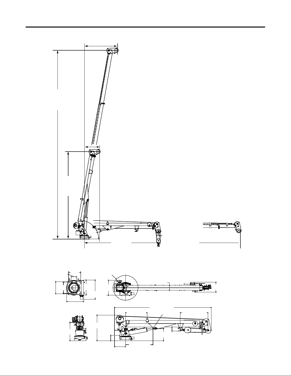
10000 25’ - Dimensional Drawings
11'-6"
(3.5 m)
24'-0"
(7.3 m)
(Fully retracted) (Fully extended)
13'-9"
(4.2 m)
26'-0"
(7.9 m)
(Fully
(Fully
retracted)
extended)
4'-7"
(1.4 m)
2'-5"
(0.7 m)
MOUNTING HOLE PATTERN
(FROM BASE OF CRANE)
23.4"
(59.3 cm)
18.1"
(46 cm)
6.6" (16.8 cm)
14.75"
(37.5 cm)
20.8" (52.8 cm)
13.75"
(34.9 cm)
14.75"
(37.5 cm)
RADIUS 20" (51 cm)
SWING CLEARANCE
15.9"
(40.4 cm)
8" (20.3 cm)
24"
(61.0 cm)
TOP VIEW
29.6"
(75 cm)
41.2"
(104.7 cm)
8.7"
(22.1 cm)
17.75"
(45.1 cm)
CENTER
OF GRAVITY
19.7"
(50.0 cm)
44.0" (111.8 cm)
44.75" (113.7 cm)
155.4" (394.7 cm)
6.5"
(16.5 cm)
34.9" (88.6 cm)
Section - 2 9 Specications
Series III Telescopic - Manual # 99905184
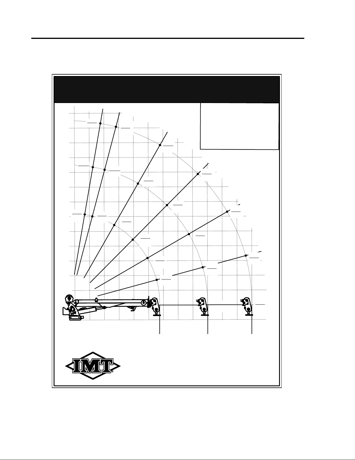
10000 25’ - Crane Capacity Load Chart
70399108
REVISIONS
REV ECO/CN DESCRIPTION DATE BY
70399108
CAPACITY CHART -
10,000-25' CRANE
3-30-11
IOWA MOLD TOOLING CO., INC
BOX 189, GARNER, IA 50438
TEL: 641-923-3711 FAX: 641-923-2424
TECH PUBS GENERATED DRAWING
DRAWN BY
APPROVED BY DATE
DATE SCALE
TITLE
SIZE DWG NO
PAT
A
FULL
SHTOF
1 1
NOTES:
MATL: .OO5“ VELVET FINISH LEXAN
ADHESIVE: 3M 468 HI-PERFORMANCE APPLIED AFTER SCREENING
SIZE: 5.5” W x 7.5" H
COLORS: BLACK ON WHITE BACKGROUND, AS SHOWN
VENDOR: CREATIVE SCREEN PRINT (CRE10) OR EQUIV.
IOWA MOLD TOOLING CO., INC.
25' 10000 HYDRAULIC CAPACITY CHART
TEL: 641-923-3711 FAX: 641-923-2424
BOX 189, GARNER, IA 50438-0189
80° 75°
60°
45°
30°
15°
0°
A 11493 CHANGED 11 TO 11.5' REACH; 6-1-11 PAT
17.25' TO 18'; 23.5' TO 24',
WIRE ROPE DATA:
DIAMETER: 0.44, NON-ROTATION RESISTANT, MINIMUM BREAKING LOAD: 20400.
B 277 ADDED WIRE ROPE INFORMATION
PER ASME B30 5-1.1.3
12-14-15 BKS
CREPLACE VALUE BOXES, ADD
GRIDS.
4-27-16 BKS
•Maximum one-part line weight
is 5500 lb.(2495kg).
•The weight of load-handling
devices is part of the load-lifted
and must be deducted from the
rated capacity.
02’- 0” 10’- 0”
6’- 0”
(0.61 m) (1.8 m) (3.0 m)
11’- 6”
(3.5 m)
14’- 0”
(4.3 m)
18’- 0”
(5.5 m)
22’- 0”
( 6.7m)
24’- 0”
( 7.3 m)
16’- 0”
20’- 0”
24’- 0”
4’- 0”
(1.2 m)
8’- 0”
(2.4 m)
12’- 0”
(3.7 m)
(4.9 m)
(6.1 m)
(7.3 m)
28’- 0”
(8.5 m)
9975 8075
4990
3850
3470
3135
2850
3945
4230
4655
5370
6435
9835
10000
10000 10000
9975
8560
7125
6515
6270
4525
3665
2265
1745
1575
1420
1295
1790
2845
1920
2110
2435
2920
4460
4535
4535
4535
4525
3885
3230
2955
277-1

This page left intentionally blank
10
Series III Telescopic - Manual # 99905184

Section - 3 11 Crane Reference
Series III Telescopic - Manual # 99905184
Section - 3Crane Reference

Section - 3 12 Crane Reference
Series III Telescopic - Manual # 99905184
10000 25’ - Greasing Instructions
Dierent lubricants are required for dierent sections of your crane. Contact your lubricant supplier for specic
product information. Follow the grease and lubricant specications and intervals listed in this manual for best
results.
Crane grease zerks must be greased on a weekly basis during normal operating conditions. Under severe
operating conditions the zerks must be greased more frequently. Each grease zerk is marked with a decal,
“grease weekly”, as shown. Rotate the worm gear bearing when greasing the worm gear bearing grease zerks.
Crane worm gear bearing teeth must be lubricated weekly with lubriplate gear shield extra-heavy or equivalent,
applied with a grease gun, caulk gun or brush. Cover all teeth with grease and leave no exposed metal surfaces
showing.
ROTATE CRANE
WHILE GREASING
TURNTABLE
GEAR-BEARING
70392524
GREASE
WEEKLY
70391612
70391612
GREASE
WEEKLY
70391613
Weekly, remove cover and lubricate with
IMT recommended
open-gear compound while rotating crane.
IMT part number: 89086244
70392399
Section - 3 13 Crane Reference
Series III Telescopic - Manual # 99905184
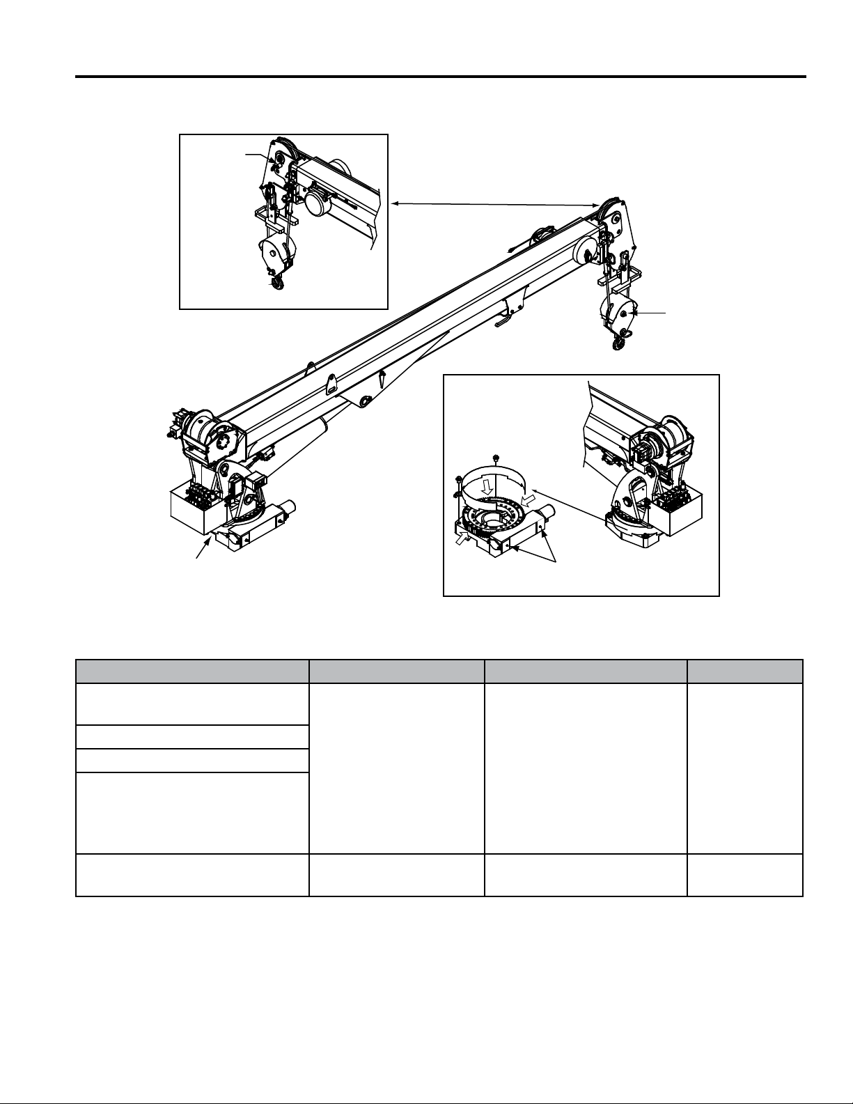
10000 25’ - Greasing Locations
LOCATION LUBRICANT APPLICATION METHOD FREQUENCY
Base - Turntable Bearing
Grease Zerk
Extreme Pressure
Lithium grease such as:
Shell Alvania 2EP
Shell Retinax “A”
Mobilgrease XHP 462,
Cenex ML 365,
Xtreme True-Flo MP
EP2 Lithium grease or
equivalent
Apply with hand or
pneumatic pressure grease
gun
Weekly
Flip Sheave Pin
Snatch Block Pin
Worm Gear Bearings
Grease Zerks (*Rotate crane
while greasing)
Rotation Worm Gear Teeth Molub-Alloy 882 or
equivalent Brush or spray on Weekly
Flip
Zerk
Sheave
Snatch
Zerk
Block
Worm Gear Grease Zerks
Turntable
Grease
Bearing
Zerk
Opposite Side of Crane
NOTE:
Remove guard. Grease
worm gear teeth with
Molub-Alloy 936 or
equivalent. Spray or
brush on.
Rotated view

Section - 3 14 Crane Reference
Series III Telescopic - Manual # 99905184
10000 25’ - Crane Recommended Spare Parts List
BASE & MAST
PART NO. DESCRIPTION QTY
73051919 MOTOR-HYD 101-2638-009 1
72601949 CAP SCR .50-13X 1.25 SH ZINC 2
72601629 CAP SCR .75-10X 4.00 HH GR8 Z 4
72060177 CAP SCR .62-11X 3.00 HH GR8 Z 16
BOOM ASSEMBLY
60030336 WEAR PAD-RC 0.19 X 6.00 X 6.00 1
60030337 WEAR PAD-RND 0.19X 2.00X 1.00X 1.00 2
60030421 WEAR PAD-RC 0.25X 6.00X 6.00 1
60030422 WEAR PAD-RND SIII EXT CYL 1
60030423 WEAR PAD-RC 0.25X 6.00X 2.25 4
60030428 WEAR PAD-RND 0.25X 2.00X .75X .44 4
60030425 WEAR PAD-RND 0.44X 1.25X .50X .50 2
ANTI-TWO-BLOCK ASSEMBLY
77041863 LIMIT SWITCH 1
CRANE & WINCH ASSEMBLY
60140915 PIN-TYPE NN 2.00X13.75 2
60140916 PIN-TYPE NN 2.00X 9.50 1
70734176 HOOK-FREE SWIVEL 5 TON (Eective through Jan 2018) A/R
71073035 HOOK-SWVL L322AN-5T W/LATCH (Eective through Jan 2018) A/R
70735099 HOOK-SWVL POS LOCK BBRG 5TON (Eective Jan 2018) A/R
70580168 WIRE ROPE ASM-.44(6X25)X100ft LH LAY 1
60030255 SHEAVE- 9.00 POLYMER 1
LOWER CYLINDER (51722956)
94399133 SEAL KIT 1
51723932 CYLINDER (Part of 51723605 Ext. Cylinder Assembly)
94399160 SEAL KIT 1
51733930 CYLINDER (Part of 51723605 Ext. Cylinder Assembly)
94399162 SEAL KIT 1
WINCH (70570771)
94744147 SEAL KIT FOR 70570771 1
71411143 BALL BEARING 1
71734007 VALVE-CBAL BRADEN - CART FOR 70570771 1
VALVE BANK (73734727)
94399213 SEAL KIT, CONNECTION BLOCK 1
94399214 SEAL KIT, VALVE SECTIONS 1
77040598 COIL-PSL 12VDC DEUTSCH 4
VALVE BANK (73734472)
90744198 KIT-COIL REPAIR FOR 73540375 12V 8
77041930 SOLENOID TUBE USED ON 73540375 8

Section - 3 15 Crane Reference
Series III Telescopic - Manual # 99905184
10000 25’ - Installation Introduction
GENERAL
This section contains instructions for the installation of your crane. Prior to installing the crane and hy-
draulic components, make sure that the chassis is ready to receive the crane. (See Installation Section
of the IMT Telescopic Crane Operation & Safety Manual, 99905190.)
Reinforce the chassis frame, as necessary, and install the PTO and pump.
Each installation may vary in components used. It is important to use hoses of proper length, pumps
of correct size, and PTO’s of adequate speed. Study the applicable installation kit in the parts section
before attempting any installation.
CRANE INSTALLATION
In addition to meeting minimum chassis specications, there must be sucient room to mount the
crane and the platform must be strong enough to support the crane and rated load. Install the crane
only on an IMT designed and approved truck body. The body must be designed to sustain the forces
imposed by the crane when lifting the full rated load. In addition, an IMT designed body is designed to
take full advantage of the standard reservoir placement. This reservoir is installed in the cargo area of
the body. The body must be installed before attempting to install the crane.
Section - 3 16 Crane Reference
Series III Telescopic - Manual # 99905184
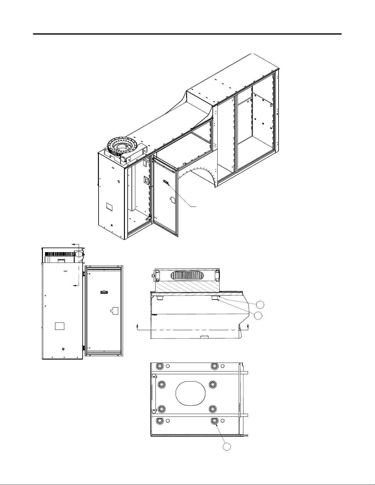
10000 25’ - Crane Installation Kit (99905067)
SECTION E-E
SCALE 0.13 : 1
SECTION J-J
SCALE 0.26 : 1
1
5
7
USE CUT WASHERS WHERE NEEDED
TO CLEAR CRANE COMPT. STRUCTURE
J
J
E
E
LEVEL INDICATOR TO BE INSTALLED
PARALLEL TO DOOR REINFORCEMENTS.
This manual suits for next models
1
Table of contents
Other IMT Construction Equipment manuals


