IMT TH20K167 User manual
Manual # 99905542
TH20K167 Manual
Revised 20141008
IOWA MOLD TOOLING CO., INC.
PO Box 189
Garner, IA 50438
Tel: 641-923-3711 FAX: 641-923-2424
Website: http://www.imt.com
Copyright © 2014 Iowa Mold Tooling Co., Inc.
All rights reserved
No part of this publication may be reproduced, stored in a retrieval system, or transmitted in any
form or by any means, electronic, mechanical, photocopying, recording or otherwise without the
prior written permission of Iowa Mold Tooling Co., Inc.
Iowa Mold Tooling Co., Inc. is an Oshkosh Corporation Company.
Courtesy of Crane.Market


i
Contents
Revisions ....................................................................................................................................................iii
Tirehand Introduction 5
TH20K167 Specifications 7
General Specifications..................................................................................................................................8
Dimensional Drawing, Forklift Mounting ....................................................................................................9
Dimensional Drawing, Loader Mounting...................................................................................................10
Capacity Chart............................................................................................................................................11
Installation 13
Tirehand Installation Introduction ..............................................................................................................14
Typical Tirehand Hydraulic Installation.....................................................................................................15
Loader Installation......................................................................................................................................16
Lift Truck Installation.................................................................................................................................17
Bulkhead Installation..................................................................................................................................18
Valvebank Installation................................................................................................................................19
Operation 21
Operator Training .......................................................................................................................................21
Tirehand Intended Use and Identification...................................................................................................22
TH20K167 Component Identification........................................................................................................22
Tirehand Equipment Inspection..................................................................................................................23
Work Station Positioning............................................................................................................................23
Tirehand Controls.......................................................................................................................................24
Tirehand Fallback Arms .............................................................................................................................25
Tirehand Task Performance........................................................................................................................26
Tirehand Operating Restrictions.................................................................................................................28
Tirehand Electrical Safety ..........................................................................................................................29
Tirehand Warnings .....................................................................................................................................30
Maintenance 33
Tirehand Maintenance Introduction............................................................................................................33
Tirehand Lubrication Points .......................................................................................................................34
Purging Tirehand Trapped Air....................................................................................................................34
Hydraulic System........................................................................................................................................34
Tirehand Preventative Maintenance ...........................................................................................................35
Tirehand Inspection Chart ..........................................................................................................................37
Tirehand Repair 39
Tirehand Troubleshooting...........................................................................................................................40
Tirehand Cylinders .....................................................................................................................................41
Courtesy of Crane.Market
ii Contents
Replacement Parts ......................................................................................................................................42
Tirehand Hydraulic Motors ........................................................................................................................43
Tirehand Relief Valve Adjustment .............................................................................................................43
Tirehand Bearings.......................................................................................................................................44
Turntable Bearing Thread Tightening Sequence ........................................................................................46
Turntable Bearing Inspection......................................................................................................................47
Thread Torque Chart (English)...................................................................................................................48
Thread Torque Chart (Metric) ....................................................................................................................49
Tirehand Parts 51
Tirehand Parts Ordering Information..........................................................................................................52
Hand Assembly (40724866).......................................................................................................................53
Sub Base Assembly (40724867).................................................................................................................55
Body Assembly (40724868).......................................................................................................................56
Clamp Assembly (40724869).....................................................................................................................57
Sub Base Assembly - Short (40724903).....................................................................................................58
Sub Base Assembly w/o Side Shift (40724910).........................................................................................59
Cylinder (51724564)...................................................................................................................................60
Cylinder (51724567)...................................................................................................................................61
Cylinder (3B282930)..................................................................................................................................62
Cylinder (3B287930)..................................................................................................................................63
Camera Kit – Dual (40724922) ..................................................................................................................64
Hydraulic Kit w/Valve Bank (91724907)...................................................................................................65
Valvebank (73734735) ...............................................................................................................................66
Valvebank Schematic (73734735)..............................................................................................................67
Hydraulic Kit w/o Valve Bank (91724923)................................................................................................68
Harness – Tirehand Radio Remote (77441524)..........................................................................................69
Harness – Tirehand Chassis Interface(77441525)......................................................................................71
Harness – Tirehand Radio Remote (77441525)..........................................................................................72
Decal Kit (95724918) .................................................................................................................................73
Recommended Spare Parts .........................................................................................................................74
Radio Remote 75
Camera Option 77
Camera Kit – Dual (40724922) ..................................................................................................................78
MONITOR-DUAL VISION
(77734784)
.................................................................................................79
Camera-For Dual Vision Monitor
(77734785)
.......................................................................................103
Cable-Coax 65’ for Dual Vision Monitor (77734786) .............................................................................107
Courtesy of Crane.Market

iii
Revisions
DATE
LOCATION
DESCRIPTION
20130603
Pages 51-64
Added parts information.
20130711
Chapter 8
Added camera option information per engineering.
20131003
73734735
Added per engineering mark-up
20131010
Chapter 8/9
Added Radio Remote Chapter 8. Chapter 9 was 8.
20141008
Chapter 7
Added cylinders.
40724866
ECN 12249 – Added 53000700, 72053638, 72060738 & 7Q072112
40724868 ECN 12249 – Added 53000713, 72053301, 72053508, 72531130 & 77045927
40724867
ECN 12250 – 51724677 was 51724564
Courtesy of Crane.Market

5
This manual includes operation, safety, and maintenance instructions and replacement parts for
your IMT Tirehand.
In addition to reading the manual, it is your responsibility to become familiar with government
regulations, hazards, and the specific operation of your equipment. Use caution and common
sense while operating and maintaining the equipment and follow all safety procedures and
regulations. Treat this equipment with respect and service it regularly.
MODIFICATIONS
Modifications to your equipment must be performed with IMT approved accessories, parts and
optional equipment. If in doubt, contact IMT prior to making any modifications. DO NOT alter or
modify any safety device! All safety devices must be inspected, tested and maintained in proper
working condition.
Decals regarding safety and operation are considered safety equipment, and must be kept clean
and legible.
The equipment owner and/or designated employee is responsible for informing all operators,
maintenance personnel, and others involved in equipment operation about the safe operation and
maintenance of the equipment. If questions arise concerning safe operation, contact IMT or your
IMT distributor for clarification.
WARRANTY
Warranty of this unit will be void on any part of the unit subjected to misuse due to overloading,
abuse, lack of maintenance and unauthorized modifications. No warranty - verbal, written or
implied - other than the official, published IMT new machinery and equipment warranty will be
valid with this unit.
NOTICE TO THE OWNER / USER
If your equipment is involved in a property damage accident, contact your IMT distributor
immediately and provide them with the details of the accident and the serial number of the
equipment. If an accident involves personal injury, immediately notify your distributor and IMT
Technical Support at:
IOWA MOLD TOOLING CO., INC.
500 HWY 18 WEST
GARNER, IA 50438
641 - 923 - 3711
Tirehand Introduction
CHAPTER 1
Courtesy of Crane.Market
6 TH20K167 Manual #99905542
RESPONSIBILITY
It is the user’s responsibility to maintain and operate this unit in a manner that will result in the
safest working conditions possible. In addition, it is the user’s responsibility to be aware of
existing Federal, State, and Local codes and regulations governing the safe use and maintenance
of this equipment.
MANUAL STRUCTURE
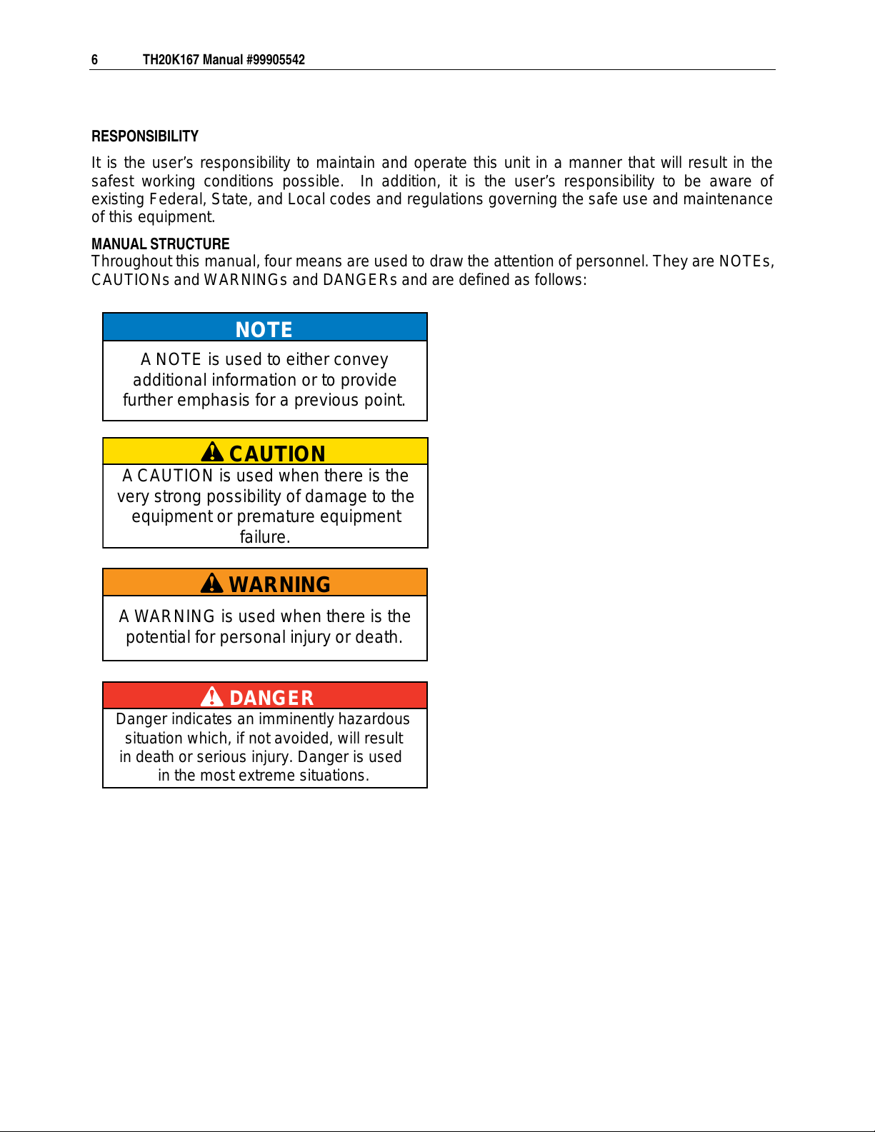
Throughout this manual, four means are used to draw the attention of personnel. They are NOTEs,
CAUTIONs and WARNINGs and DANGERs and are defined as follows:
NOTE
ANOTE is used to either convey
additional information or to provide
further emphasis for a previous point.
CAUTION
ACAUTION is used when there is the
very strong possibility of damage to the
equipment or premature equipment
failure.
WARNING
A WARNING is used when there is the
potential for personal injury or death.
DANGER
Danger indicates an imminently hazardous
situation which, if not avoided, will result
in death or serious injury. Danger is used
in the most extreme situations.
Courtesy of Crane.Market

7
In This Chapter
General Specifications..............................................................8
Dimensional Drawing, Forklift Mounting....................................9
Dimensional Drawing, Loader Mounting...................................10
Capacity Chart..........................................................................11
CHAPTER 2
TH
20K167 Specifications
Courtesy of Crane.Market
8 TH20K167 Manual #99905542
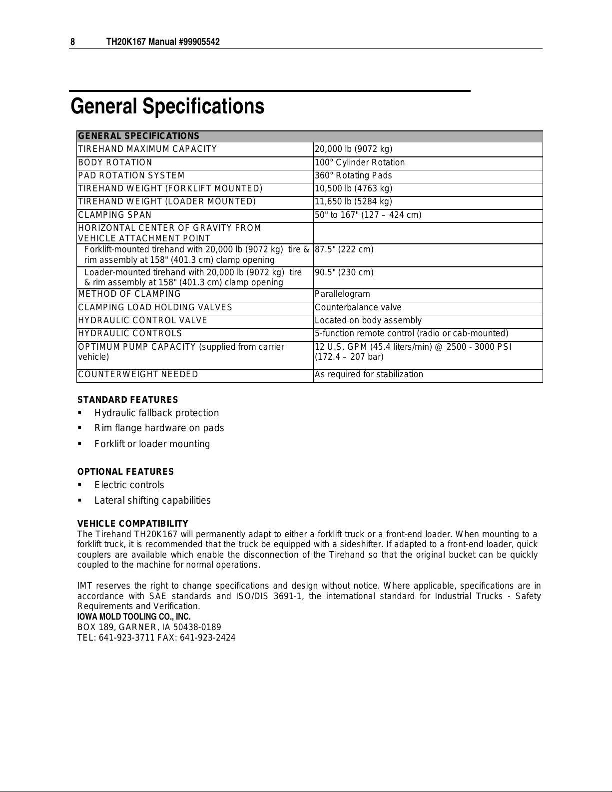
General Specifications
GENERAL SPECIFICATIONS
TIREHAND MAXIMUM CAPACITY 20,000 lb (9072 kg)
BODY ROTATION
100° Cylinder Rotation
PAD ROTATION SYSTEM
360° Rotating Pads
TIREHAND WEIGHT (FORKLIFT MOUNTED)
10,500 lb (4763 kg)
TIREHAND WEIGHT (LOADER MOUNTED)
11,650 lb (5284 kg)
CLAMPING SPAN
50" to 167" (127 – 424 cm)
HORIZONTAL CENTER OF GRAVITY FROM
VEHICLE ATTACHMENT POINT
Forklift-mounted tirehand with 20,000 lb (9072 kg) tire &
rim assembly at 158" (401.3 cm) clamp opening
87.5" (222 cm)
Loader-mounted tirehand with 20,000 lb (9072 kg) tire
& rim assembly at 158" (401.3 cm) clamp opening
90.5" (230 cm)
METHOD OF CLAMPING
Parallelogram
CLAMPING LOAD HOLDING VALVES
Counterbalance valve
HYDRAULIC CONTROL VALVE
Located on body assembly
HYDRAULIC CONTROLS
5-function remote control (radio or cab-mounted)
OPTIMUM PUMP CAPACITY (supplied from carrier
vehicle)
12 U.S. GPM (45.4 liters/min) @ 2500 - 3000 PSI
(172.4 – 207 bar)
COUNTERWEIGHT NEEDED
As required for stabilization
STANDARD FEATURES
Hydraulic fallback protection
Rim flange hardware on pads
Forklift or loader mounting
OPTIONAL FEATURES
Electric controls
Lateral shifting capabilities
VEHICLE COMPATIBILITY
The Tirehand TH20K167 will permanently adapt to either a forklift truck or a front-end loader. When mounting to a
forklift truck, it is recommended that the truck be equipped with a sideshifter. If adapted to a front-end loader, quick
couplers are available which enable the disconnection of the Tirehand so that the original bucket can be quickly
coupled to the machine for normal operations.
IMT reserves the right to change specifications and design without notice. Where applicable, specifications are in
accordance with SAE standards and ISO/DIS 3691-1, the international standard for Industrial Trucks - Safety
Requirements and Verification.
IOWA MOLD TOOLING CO., INC.
BOX 189, GARNER, IA 50438-0189
TEL: 641-923-3711 FAX: 641-923-2424
Courtesy of Crane.Market

Chapter 2 TH20K167 Specifications 9
Dimensional Drawing, Forklift Mounting
Dimensions in inches (mm).
167"
83" (2110)
50"
100" (2540) (1270) (4242)
15"
(381)
87.5" CG (2222) with 10,500 lb (4763 kg)
& rim. 158" (4013) between pads
tirehand and 20,000 lb (9072 kg) tire
111.5" (2832) from mounting surface
to centerline of tire
ø35.5" (902)
Courtesy of Crane.Market

10 TH20K167 Manual #99905542
Dimensional Drawing, Loader Mounting
Dimensions in inches (mm).
167"
83" (2110)
50"
100" (2540) (1270) (4242)
15"
(381)
90.5" (2300 cm) CG with 11,650 lb (5284 kg)
158" (4013 cm) between pads.
tirehand and 20,000 lb (9072) tire & rim.
117.5" (2885) from mounting surface
to centerline of tire
ø35.5" (902)
Courtesy of Crane.Market


13
In This Chapter
Tirehand Installation Introduction..............................................14
Typical Tirehand Hydraulic Installation .....................................15
Loader Installation....................................................................16
Lift Truck Installation.................................................................17
Bulkhead Installation ................................................................18
Valvebank Installation...............................................................19
CHAPTER 3
Installation
Courtesy of Crane.Market

14 TH20K167 Manual #99905542
Tirehand Installation Introduction
VEHICLE COMPATABILITY
The tirehand will permanently adapt to either a forklift truck or a front-end loader which has
sufficient capacity and stability, per the tirehand specifications. When mounting to a forklift
truck, it
is recommended that the truck be equipped with a sideshift. If adapted to a front-end loader, quick
couplers are available which enable the disconnection of the tirehand so that the original bucket
can be quickly coupled to the machine for normal operations.
Typical tirehand hydraulic installations include:
Bulkhead plate hydraulic installation - all of the tirehand hydraulics hoses connect together
in
a
bulkhead plate, which then connects hydraulically to the loader or forklift. With a bulkhead
plate installation, the valvebank is part of the forklift or loader rather than the tirehand. In
many cases, bulkhead installations are used on forklifts.
Valvebank hydraulic installation - when the valvebank is part of the tirehand, rather than the
loader or forklift. The forklift or loader must be equipped with a pressure line and a return line
which connects the forklift or loader hydraulic system to the valvebank in the tirehand. In
many cases, valvebank hydraulic installations are used on loaders.
Typical tirehand controls include:
Hydraulic cab controls, where additional functions in forklift or loader control valves are
hydraulically connected to the tirehand.
Electric cab controls, which includes a control box with toggles used to control the tirehand.
Radio remote controls.
For all installations, the tirehand requires 12 GPM (45.4 lpm) of hydraulic fluid at 2500 – 3000 PSI
(172.4 - 206.8 bar). A flow divider may be required if the forklift or loader pump provides excess
flow. Contact IMT for specific installation instructions on any type of installation.
Prior to connecting any electrical connections between the tirehand and the loader or forklift,
check the tirehand voltage. IMT tirehands may be 12V or 24V.
Courtesy of Crane.Market

Chapter 3 Installation 15
Typical Tirehand Hydraulic Installation
For all installations, the tirehand requires 12 GPM (45.4 lpm) of hydraulic fluid at 2500 – 3000
PSI (172.4 - 206.8 bar). Some of the components shown on the typical hydraulic installation
drawing, including the flow dividers, reservoir, filter, pump, and drain, are not provided by
IMT
but
are part of the loader or forklift. Contact IMT for specific installation instructions on any type
of installation.
Courtesy of Crane.Market

16 TH20K167 Manual #99905542
Loader Installation
NOTE: Tirehand installations vary based on the carrier vehicle. Contact IMT for specific
installation assistance.
1 Mount the Tirehand to loader arms using the original loader pins.
2 Splice the flow control divider into the existing pressure line. Continue the original line to its
original destination (bucket, etc.), and route the controlled line (with 12 gpm (45.4 lpm) at
2500 - 3000 psi (172.4 - 206.8 bar)) to the tirehand
valvebank.
3 Route the hoses as shown in figure below.
4 Locate the control handle inside the cab where convenient to operate.
5 Connect the 3-wire power cable to 12-volt power. The green wire connects to 12V positive,
the black wire to the coil on the flow divider, and the white wire to ground.
6 Route the control cable to the tirehand and connect.
7 Check all hoses and cables for clearances. Make sure that steering or moving the arms will
not pinch or overstress the hoses or cables.
8 Fill the reservoir. Start the loader’s engine and operate all controls to purge air from the
system. With the loader running, check for leaks and repair if necessary.
9 Recheck all hoses and cables for clearance.
10 Check the reservoir oil level and fill if necessary.
11 Test operate the tirehand.
NOTE
Stop blocks should be welded to the loader
arms to limit articulation, if necessary
Locationsand sizes of stops to be
determined at time of installation.
Courtesy of Crane.Market
Chapter 3 Installation 17
Lift Truck Installation
1 Mount the Tirehand to lift truck using the original carriage pin.
2 Splice the flow control divider into the existing pressure line. Continue the original line to its
original destination (forklift function, etc.), and route the controlled line (with 12 gpm (45.4 lpm)
at 2500-3000 psi (172.4 - 206.8 bar)) to the tirehand valvebank.
3 Route the hoses as shown in figure below.
4 Locate the control handle inside the cab where convenient to operate.
5 Connect the 3-wire power cable to 12-volt power. The green wire connects to 12V positive,
the black wire to the coil on the flow divider, and the white wire to ground.
6 Route the control cable to the Tirehand and connect.
7 Check all hoses and cables for clearances. Make sure that steering or other movements of
the lift truck will not pinch or overstress the hoses or cables.
8 Fill the reservoir. Start the lift truck’s engine and operate all controls to purge air from the
system.
9 With the lift truck running, check for leaks and repair if necessary.
10 Re-check all hoses and cables for clearance.
11 Check the reservoir oil level and fill if necessary.
12 Test operate the Tirehand.
Courtesy of Crane.Market
18 TH20K167 Manual #99905542
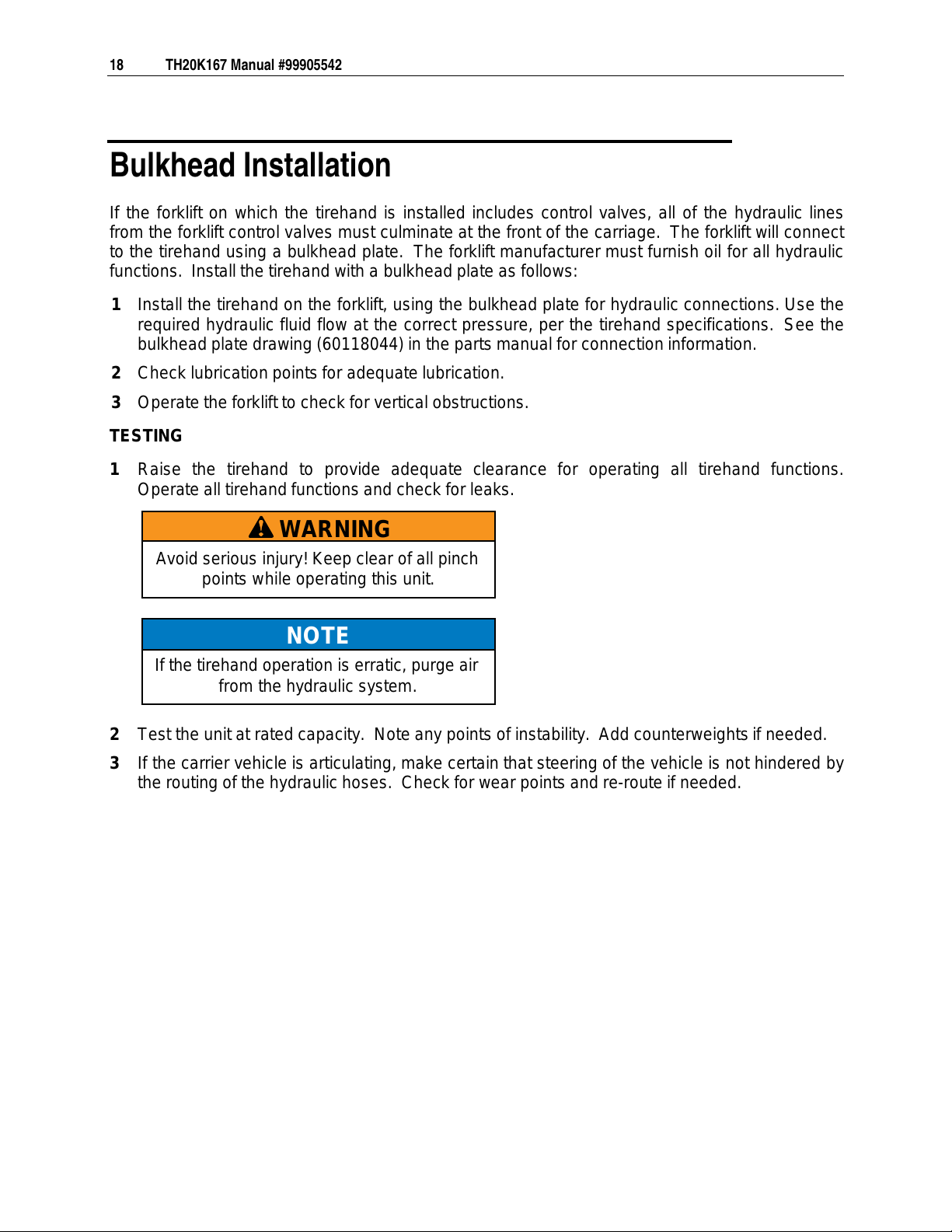
Bulkhead Installation
If the forklift on which the tirehand is installed includes control valves, all of the hydraulic
lines
from
the forklift control valves must culminate at the front of the carriage. The forklift will connect
to the tirehand using a bulkhead plate. The forklift manufacturer must furnish oil for all hydraulic
functions. Install the tirehand with a bulkhead plate as follows:
1 Install the tirehand on the forklift, using the bulkhead plate for hydraulic connections. Use the
required hydraulic fluid flow at the correct pressure, per the tirehand specifications. See the
bulkhead plate drawing (60118044) in the parts manual for connection information.
2 Check lubrication points for adequate lubrication.
3 Operate the forklift to check for vertical obstructions.
TESTING
1 Raise the tirehand to provide adequate clearance for operating all tirehand functions.
Operate all tirehand functions and check for leaks.
2 Test the unit at rated capacity. Note any points of instability. Add counterweights if needed.
3 If the carrier vehicle is articulating, make certain that steering of the vehicle is not hindered by
the routing of the hydraulic hoses. Check for wear points and re-route if needed.
WARNING
Avoid serious injury! Keep clear of all pinch
points while operating this unit.
NOTE
If the tirehand operation is erratic, purge air
from the hydraulic system.
Courtesy of Crane.Market
Table of contents
Other IMT Construction Equipment manuals


Popular Construction Equipment manuals by other brands


Sealey
Sealey DF760.V2 instructions

WilTec
WilTec 61327 Operation manual

Metreel
Metreel MET-TRACK Installation & maintenance instructions

Soosan
Soosan SQ Series Operations manual & parts list

Terex
Terex AL4L operators manual with maintenance information

ThorWorks Industries
ThorWorks Industries SealMaster 300 Series owner's manual