IMT 3203i User manual

IOWA MOLD TOOLING CO., INC.
P.O. Box 189
Garner, IA 50438
Tel: 641.923.3711
Fax: 641.923.2424
www.imt.com
Revised 08-18-2020
Copyright © 2020 Iowa Mold Tooling Co., Inc.
All rights reserved
No part of this publication may be reproduced, stored in a retrieval system, or transmitted in any form or by any
means, electronic, mechanical, photocopying, recording or otherwise without the prior written permission of Iowa
Mold Tooling Co., Inc.
Iowa Mold Tooling Co., Inc. is an Oshkosh Corporation Company
3203i
Parts &
Specifications
Manual # 99904380

ii
3203i - Manual # 99904380
Operating, servicing and maintaining this vehicle
or equipment can expose you to chemicals
including engine exhaust, carbon monoxide,
phthalates, and lead, which are known to the
State of California to cause cancer and birth
defects or other reproductive harm. To minimize
exposure, avoid breathing exhaust, do not idle the
engine except as necessary, service your vehicle
or equipment in a well-ventilated area and wear
gloves or wash your hands frequently when
servicing. For more information go to
www.P65Warnings.ca.gov.
70490167
70490167
PROP 65
BKS 5-29-18
ORANGE , BLACK AND WHITE
3.27” 2.70”
CN

iii
3203i - Manual # 99904380
Table of Contents
Introduction 1
Introduction ....................................................................................................................................................2
Specications 3
3203i Technical Data......................................................................................................................................4
Load Capacity Chart ......................................................................................................................................6
Geometric Conguration ................................................................................................................................7
Pump & Motor Performance ..........................................................................................................................8
Assemblies & Grease Zerk Locations..........................................................................................................10
3203i Recommended Spare Parts List ........................................................................................................ 11
Crane Installation (99904394)......................................................................................................................13
Electric Crane Battery Circuit (99904884) ...................................................................................................20
Telescopic Crane Orientation.......................................................................................................................21
Electric Crane Control..................................................................................................................................22
Parts 23
Parts Information..........................................................................................................................................24
Electric Crane Power Safety ........................................................................................................................26
Base & Mast Assembly (99904315).............................................................................................................28
99904315 With Mte Power Unit ...................................................................................................................32
MTE Replacement Power Unit Instuctions (52725032-SERVICE) ..............................................................35
Valve Bank (73734304)................................................................................................................................36
Cylinder, Lower (51721267).........................................................................................................................38
Boom Assembly (99904316)........................................................................................................................40
Crane & Winch Assembly (99904317) .........................................................................................................50
Cord Reel – 6.7m, Electric 2 – Wire (70735052) .........................................................................................58
Cord Reel Assembly, 4.17’ W/Packard Connector (51727064) ...................................................................59
Snatch Block (51724950).............................................................................................................................60
Cylinder, Extension (51725007)...................................................................................................................62
Cylinder, Extension (51722111) ...................................................................................................................64
Cylinder, Extension (51721291)...................................................................................................................66
Winch (71570922)........................................................................................................................................68
Power Unit (73511432) ................................................................................................................................69
Power Unit 73511283 (12V) & 73511305 (24V) ...........................................................................................70
Hydraulic Installation (99904361) ................................................................................................................72
Tethered Control Installation (99904593).....................................................................................................77
Radio Control Installation, Standard (99904594).........................................................................................78
Radio Control Installation, Proportional (99904595) ....................................................................................79
Lighting & Electrical 81
Electrical Installation (99904389).................................................................................................................82
Cable Assembly (51726427)........................................................................................................................84
Light Kit (99906234).....................................................................................................................................85
275 & 225-Amp Contactor Replacement (99904578 ...................................................................................92
Harness, Radio (77441270).........................................................................................................................94
Harness, Tethered (77441269) ....................................................................................................................96
Harness, LED Boom Tip Jumper (77441689) ............................................................................................102
Harness, Light SW A2B CRD Reel (77441674) ........................................................................................104
Harness, Limit Switch Jumper (77441678) ................................................................................................106
Protective Sleeve Installation (70034573) .................................................................................................107

iv
3203i - Manual # 99904380
General Information 109
Decal Installation (99904375) .................................................................................................................... 110
Turntable Bearing Thread Tightening Sequence ....................................................................................... 113
Thread Torque Chart.................................................................................................................................. 114

v
3203i - Manual # 99904380

vi
3203i - Manual # 99904380

Introduction 1 Section - 1
3203i - Manual # 99904380
IntroductionSection - 1

Introduction 2 Section - 1
3203i - Manual # 99904380
Introduction
This manual includes parts, specications, and installation information for your particular crane. It is your
responsibility to maintain and operate this unit in a manner that will result in the safest working conditions possible.
Warranty of this unit will be void on any part of the unit subjected to misuse due to overloading, abuse, lack of
maintenance and unauthorized modications. No warranty - verbal, written or implied - other than the ocial,
published IMT new machinery and equipment warranty will be valid with this unit. In addition, it is also the user’s
responsibility to be aware of existing Federal, State and Local codes and regulations governing the safe use
and maintenance of this unit. This crane was designed and built to meet the standards of ANSI/ASSE A10.31-
1995, Safety Requirements, Denitions, and Specications for Digger Derricks. Contact the American National
Standards Institute (www.ansi.org) for more information.
Throughout this manual, four means are used to draw the attention of personnel. They are NOTE, CAUTION and
WARNING and DANGER are dened as follows:
NOTE
A NOTE is used to either convey additional
information or to provide further emphasis for
a previous point.
CAUTION
A CAUTION is used when there is the very
strong possibility of damage to the equipment
or premature equipment failure.
WARNING
A WARNING is used when there is the
potential for personal injury or death.
DANGER
Danger indicates an imminently hazardous
situation which, if not avoided, will result in
death or serious injury. Danger is used in the
extreme situations.
For a safe work environment, treat this equipment with respect and service it regularly

Specications 3 Section - 2
3203i - Manual # 99904380
SpecificationsSection - 2

Specications 4 Section - 2
3203i - Manual # 99904380
3203i Technical Data
GENERAL SPECIFICATIONS
CRANE RATING (crane rating (ft-lb) is the rated load (lb)
multiplied by the respective distance (ft) from centerline
of rotation with all extensions retracted and lower boom in
horizontal position.)
12,000 ft-lb at 7’-6” (1.6 tm at 2.3 m)
Horizontal Reach (From Centerline Of Rotation) 15’-0” (4.6 m)
Hydraulic Extension (1) 48” (122 cm)
Manual Extension (1) 48” (122 cm)
Lifting Height (From Base of Crane to Centerline of Sheave) 16’-2” (4.9 m)
Crane Weight (1H1m) 635 lb (288 kg)
Crane Storage Height 29” (73.7 cm)
Mounting Space Required (Crane Base) 14” x 18” (35.5 cm x 45.7 cm)
Hydraulic System Operating Pressure 2500 psi (172 Bar)
Maximum Hydraulic Flow 1.6 gpm (6 L/pm)
Oil Reservoir Capacity 1.5 gallons (5.7 L)
Oil Type O VG32, low pour, anti-wear hydraulic oil
CENTER OF GRAVITY
Horizontal from Centerline of Rotation (Booms Retracted) 22.88” (58.1 cm)
Horizontal from Centerline of Rotation (Booms Extended) 22.88” (58.1 cm)
Vertical from Bottom of Crane Base 12.75” (32.4 cm)
Tie-Down Bolt Pattern (On Center) 12” x 12” or 11.5” x 14.75”
(30.5 cm x 30.5 cm) or (29.2 cm x 37.5 cm)
Rotation Torque 2500 ft-lb (3.4 kN-m)
CYLINDER SPECIFICATIONS
Lower Boom Cylinder 2.75” bore; 16” stroke
(7 cm bore; 40.6 cm stroke)
Extension Boom Cylinder 1.5” bore; 48” stroke
(3.8 cm bore; 122.0 cm stroke)
WINCH SPECIFICATIONS
Winch Pull Line 2000 lb (907 kg)
Pull Line Speed Without Load 23 ft/min (7 m/min)
Rope Diameter 7/32” (5.56 mm)
Wire Rope Length 65’ (19.81 m)
Cable Nominal Strength 5600 lb (2540 kg)
PERFORMANCE CHARACTERISTICS
SPECIFICATIONS SPEED
Rotation 360º (Continuous) 44 seconds
Lower Boom Elevation -5º to +75º 10 seconds
Extension Cylinder 48” (122.0 cm) 10 seconds total

Specications 5 Section - 2
3203i - Manual # 99904380
CHASSIS REQUIREMENTS
GVWR 11,500 lb (5216 kg) (Minimum)
ELECTRICAL REQUIREMENTS
System Voltage 12 Volts
Battery
Minimum of 2 identical batteries in parallel
750 CCA MIN per battery.
Must meet chassis manufacturer’s specications.
Batteries must be fully charged prior to use.
Alternator 200 Amperes MINIMUM
Engine Elevated RPM required if additional high amperage draw systems will be in use
while crane is being operated.
Duty Cycle
Duty cycle and absolute continuous on-time according to the crane user
manual.
Winch is not operated simultaneously with any other function.
Specications 6 Section - 2
3203i - Manual # 99904380
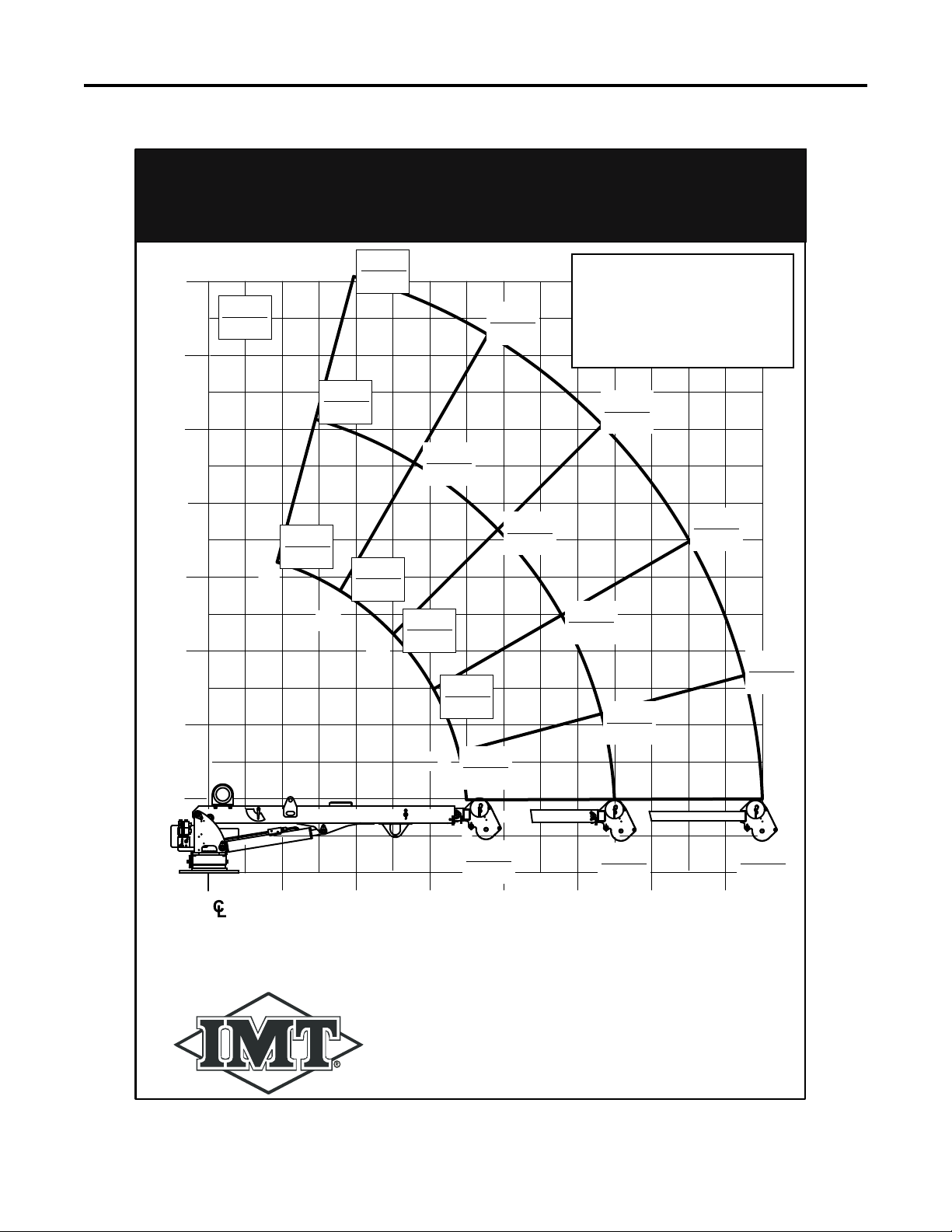
Load Capacity Chart
IOWA MOLD TOOLING CO., INC.
BOX 189, GARNER, IA 50438-0189
TEL: 641-923-3711 FAX: 641-923-2424
70397348
3203i CAPACITY CHART
10'
3.0m
12'
3.6m
14'
4.2m
16'
4.8m
0
75°
60°
45°
30°
15°
2'
0.6m
4'
1.2m
8'
2.4m
0
(Base)
6'
1.8m
DISTANCE IN FEET/METERS / LOAD IN POUNDS/KG.
Weight of load handling devices are part of the load lifted
and must be deducted from the capacity.
4000
1815 3050
1385
2460
1115
2140
970
3135
1420
2350
1065
1450
660
1990
905
1575
715
1350
615
1195
540
1140
520
975
440
850
385
1905
865
1670
755 1050
475
730
330
LB
KG
10'
3.0m 12'
3.6m 14'
4.2m
2'
0.6m 4'
1.2m 8'
2.4m
6'
1.8m
Maximum 1-part line
capacity is 2000 lb (907 kg).
For greater loads, use
2-part line.
NOTE: Boxes denote
2-part line.
Specications 7 Section - 2
3203i - Manual # 99904380
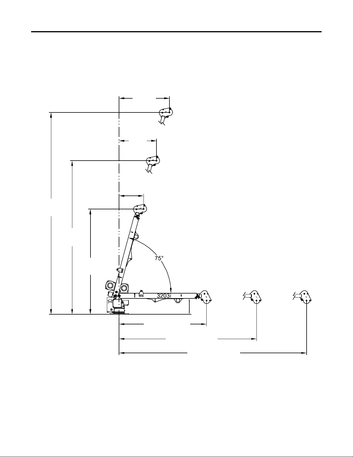
GeometricConguration
4'-0"
(1.22 m)
3'-0"
(0.91 m)
1'-11"
(0.39 m)
16'-2"
(4.92 m)
12'-3"
(3.75 m)
8'-5"
(2.60 m)
7'-0" (2.13 m)
11'-0" (3.35 m)
15'-0" (4.57 m)
1'-3" (38 cm)

Specications 8 Section - 2
3203i - Manual # 99904380
Pump & Motor Performance
The ve minute duty cycle must be adhered to. Operators have a choice of running the crane intermittently all
day, using the duty cycles per the S2 and S3 curves, or at full power for 4.5 minutes, which MUST be followed by
a complete cool-down to ambient.
180 AMPS
0
1
2
3
4
5
6
0.0
5.0
10.0
15.0
20.0
25.0
Q - 1.6 CC
I - 1.6 CC
0
50
100
150
200
300
250
0 500 1000 1500 2000 2500 3000 3500 4000 4500
PSI
BAR
0 25 50 75 100 125 150 175 200 225 250 275 300
2500 PSI
CAUTION
Avoid motor damage! Operate within
performance curves shown.

Specications 9 Section - 3
3203i - Manual # 99904380
Crane ReferenceSection - 3
Specications 10 Crane Reference
3203i - Manual # 99904380
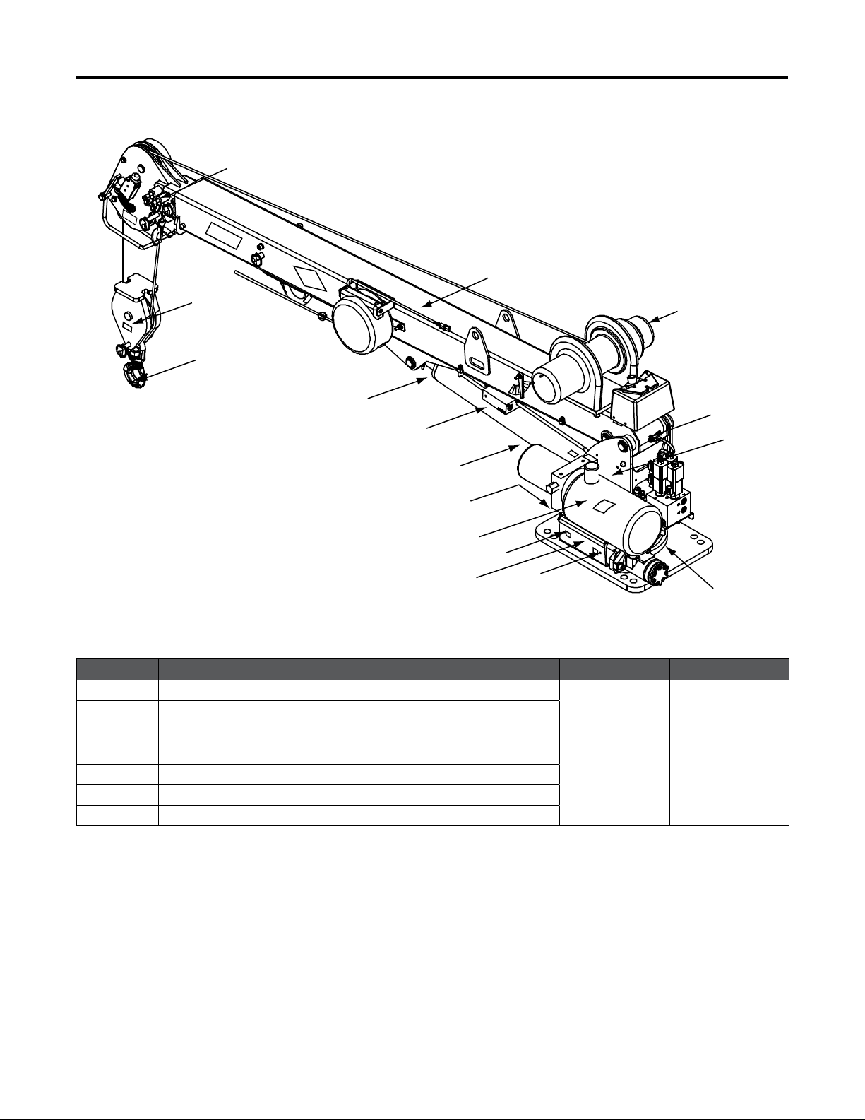
Assemblies & Grease Zerk Locations
ITEM NO. LOCATION DESCRIPTION LUBRICANT FREQUENCY
1LOWER CYLINDER ROD
SHELL
ALVANIA 2
EP
OR
SHELL
RETINAX “A:
WEEKLY
2LOWER CYLINDER BASE
3GEAR ROTATOR GREASE EXTENSION
*ROTATE CRANE WHILE GREASING.
4POWER UNIT
5POWER UNIT
6LOWER BOOM PIN
NOTE:
All application points must be greased weekly under normal workloads and moderate weather conditions.
Under severe operating conditions, lubricate more frequently. See the IMT Electric Crane Operation &
Safety manual P/N: 99905190, for additional lubrication requirements.
NOTE:
Image may be dierent depending on production date. Grease points should be identical.
4
5
LOWER
CYLINDER
3
6
CRANE
BASE
WINCH
SNATCH
BLOCK
MAST
POWER
UNIT
LOWER
BOOM
EXTENSION
BOOM
HOOK
2
1
HYDRAULIC
RESERVOIR

Specications 11 Crane Reference
3203i - Manual # 99904380
3203i Recommended Spare Parts List
51721267 LOWER CYLINDER QTY.
51744137 SEAL KIT-IMT 2.75B 1.75R 1.50 S 1
60127432 PISTON-2.75 BORE X 1.75 ROD 1.63 STGR 1
60127434 HEAD-2.75 BORE X 1.75 ROD 1
73054999 VALVE-COUNTERBALANCE 1
77041786 SWITCH-PRESS 2750 PSI 1
51722111 EXTENSION CYLINDER
94397290 SEAL KIT-IMT 1.50 BORE 1.00 ROD .75 1
60135105 HEAD-1.50 BORE X 1.00 ROD 1
60135106 PISTON-1.50 BORE X .75 STGR 1
73054999 VALVE-COUNTERBALANCE SUN01 CBBC-LHN 1
99904315 BASE & MAST ASSEMBLY
60118032 CABLE CONNECTOR MODIFICATION 1
72601931 CAP SCREW .44-14X 3.00 HH 156 KSI PROOF L 16
73511156 MOTOR-HYDRAULIC 101 1035 009 1
76039295 GASKET-GEAR 1
77441534 SWITCH- 225A CONTACTOR (12 OR 24V) 1
77441281 CABLE CONNECTOR-FEMALE 1
77441285 TERMINAL RING, INSULATED 3/8 STUD
73734304 VALVE BANK (12V)
73540327 COIL (VALVE BANK) (12V) 3
73540326 VALVE ASSEMBLY (VALVE & COIL) (12V) 6
73734375 VALVE BANK (24V)
77040527 COIL (VALVE BANK) (24V) 3
73540336 VALVE ASSEMBLY (VALVE & COIL) (24V) 6
73511283 POWER UNIT (12V)
70733826 FILL CAP ELECTRIC CRANES 1
73511171 PUMP-GEAR ELECTRIC CRANE 1
73540323 VALVE-RELIEF ELECTRIC CRANE 1
73734332 KIT-TUBE POWER UNIT ELECTRIC CRANE 1
74397392 RESERVOIR TANK ELECTRIC CRANE 1
77043060 MOTOR-POWER UNIT ELECTRIC CRANE 1
73511305 POWER UNIT (24V)
77043066 MOTOR (24V) 1
73511306 PUMP 1
73540517 RELIEF VALVE ASSEMBLY 1
74399495 RESERVOIR 1
70734788 BREATHER CAP 1
73734791 TUBE-SUCTION 1
70734792 STRAINER 1

Specications 12 Crane Reference
3203i - Manual # 99904380
99904316 BOOM ASSEMBLY QTY.
60030373 WEAR PAD- EXT CYLINDER 1
60030374 WEAR PAD-ROUND 1.00 DIA X .50 DIA X .75L 6
60030375 WEAR PAD-ROUND 3.00 DIA X 1.00 DIA X .55L 1
60030376 WEAR PAD-ROUND 3.50 X 1.00 DIA X .615 LG 2
60132302 STOP SCREW 3/8-24 X .50 4
71734311 PIN-QUICK RELEASE.62D/4.5 CRIT 1
71734314 PIN-QUICK RELEASE.62D/6.5 CRIT 1
72661543 PIN-QUICK 316-10QP 2
60030372 SHEAVE- 5.5 NYLATRON 2
60133938 WEAR PAD-ROUND 0.25 X 1.00 X 0.50 X 0.50 2
72661711 CLEVIS PIN 0.5 X 3.00 1
60030483 SHEAVE-8.0 NYLATRON 1
99904317 CRANE & WINCH ASSEMBLY
51721494 CORD REEL ASSEMBLY- 5FT PACKARD CONNECTOR 1
70580059 WIRE ROPE ASM-.22(7X19)X65FT PGA 1
71413185 SPRING-.105WIRE 0.75OD 2.875 LG 1
70735101 HOOK-SWVL POS LOCK BBRG 2TON (EFFECTIVE 1/1/2018) 1
72601798 WASHER-LOCK 12MM 4
72601935 CAP SCREW M12-1.75X 40 SH PLAIN 4
72601938 BOLT-EYE # 8-32X 1.125 1
77041459 SWITCH-LIMIT ZE-N-2S 1
77441096 CONNECTOR- .50 STR RLF .25-.38 1
71570922 WINCH (12V)
77041801 CONTACTOR (12 OR 24V) 1
77566638 BRAKE ASSEMBLY 1
77744175 BRUSH KIT 1
71570922 WINCH (24V)
77041928 CONTACTOR (12 OR 24V) 1
77566638 BRAKE ASSEMBLY 1
77744175 BRUSH KIT 1
99904394 ELECTRICAL INSTALLATION
77441116 FUSEHOLDER, HIGH AMP 1
77441219 FUSE-225 AMP 1

Specications 13 Crane Reference
3203i - Manual # 99904380
Crane Installation (99904394)
In addition to meeting the chassis requirements noted in the Technical Data section of this manual, make sure
there is sucient room for mounting the crane, and the platform is strong enough to support the crane and rated
load. Install the crane only on an IMT designed and approved truck body. The body must be designed to sustain
the forces imposed by the crane when lifting the full rated load. Install the body on the chassis before installing the
crane. Refer to the following table for parts referenced in the following crane installation drawings.
ITEM NO. PART NO. DESCRIPTION KIT NO. QTY
1. 51721572 ELECTRIC CRANE BODY INSTALLATION 1
2. 91721647 HARDWARE KIT- 3203I/4004I ELEC CRANE
BODY INSTALLATION 1
3. 91721751 HARDWARE KIT- 5005I ELEC CRANE BODY
INSTALLATION 1
5. 51725572 DRAWING-CRANE & WINCH ASSEMBLY 3203I REF
6. 60251272 BRACKET-SWITCH 300 AMP ELEC CRANE 1 & 4 1
7. 70734331 SWITCH-300A KEYED BATTERY DISCONNECT 1 & 4 1
8. 72042097 LEVEL INDICATOR LEVEL 1 & 4 1
9. 77040209 TERMINAL-RING NI .38 STUD 1 WIRE 1 & 4 1
10. 77040529 TERMINAL-RING NI .31 STUD 1-2 WIRE 4 9
11. 77441116 FUSEHOLDER-HIGH AMP2 BOLT WITH COVER 4 2
12. 77441219 FUSE-225 AMP 4 2
13. 89044276 CABLE-#1 WELDING 1 & 4 35 FT
14. 89392333 TUBE-HEAT SHRINK AMP 1 & 4 0.50 FT
15. 72060208 CAP SCREW .75-10X 2.50 HH GR8 Z 2 4
16. 72601862 NUT .75-10 HEX NYLOC GR8Z 2 4
17. 72063116 WASHER .75 N FLAT H ASTMF436Z 2 8
18 72060002 CAP SCREW .25-20X .75 HH GR5 Z 2 & 3 4
19. 72060634 SCREW-MACHINERY #10-24X .50 RDH 2 & 3 4
20. 72062000 NUT .25-20 HEX 2 & 3 4
21. 72062106 NUT 10-24 HEX NYLOCK 2 & 3 4
22. 72063001 WASHER .25 FLAT 2 & 3 8
REV. E 20120918
1. To install the crane: Use a lifting device capable of lifting the weight of the crane as indicated in the Technical
Data section of this manual. Attach fabric slings to the crane lower boom, centered approximately 18 inches (46
cm) from the mast hinge. Make certain the crane is well balanced on the slings by slowly lifting approximately
6” (15 cm) o the ground. Lift the crane and apply a bead of waterproof compound, such as silicon based caulk,
to the bottom of the base. Move the chassis under the crane and lower the crane into the desired position.
NOTE:
Install the 3/4-10x2.5” mounting cap screws (item # 15) and 3/4” washers (item #16) to secure the crane base to the
truck body (see gure on next page). Torque the cap screws to 280 ft-lb.
Specications 14 Crane Reference
3203i - Manual # 99904380
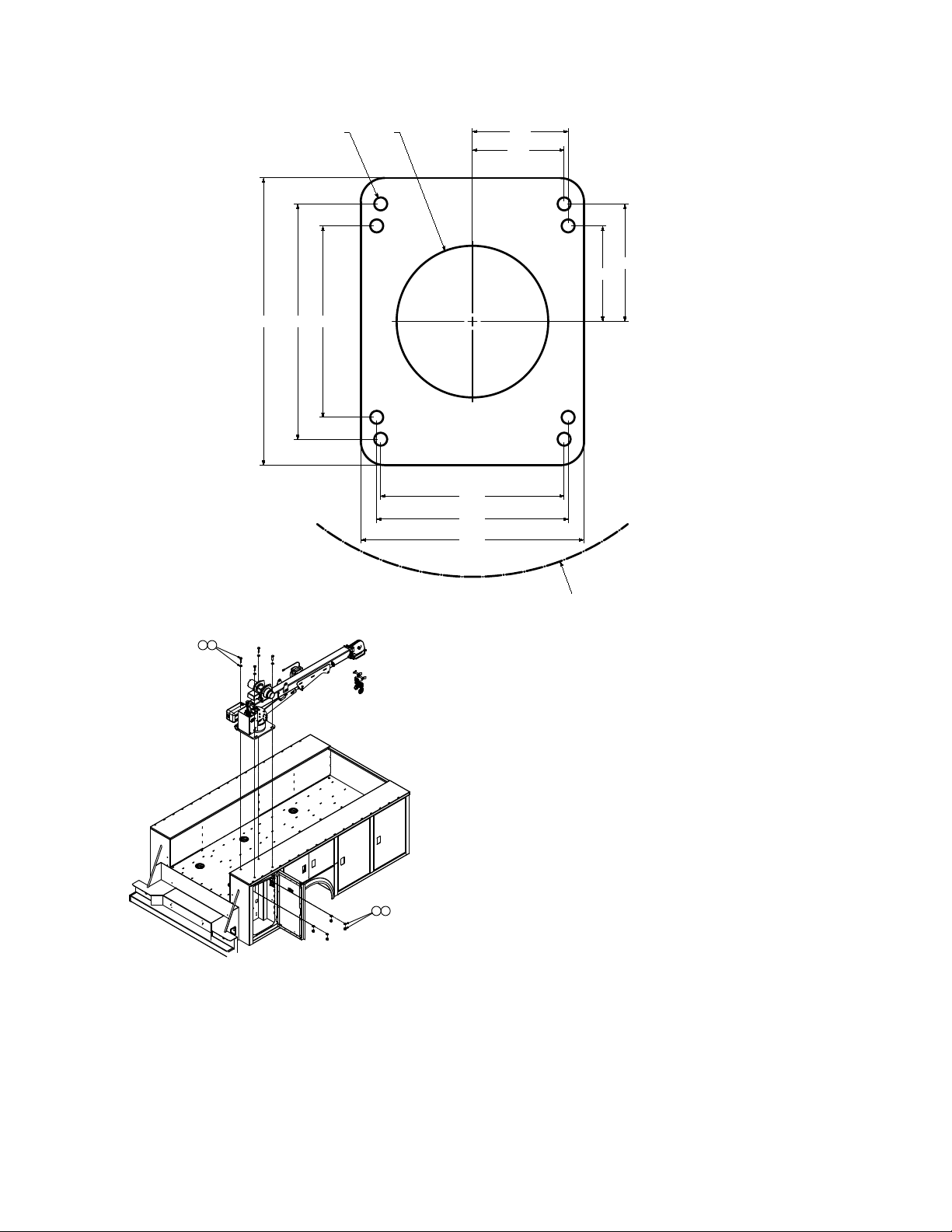
CRANE INSTALLATION - CONTINUED
14.75 12.0018.00
11.50
12.00
14.00
5.75
6.00
6.00
7.38
9.50
0.81
3203I/4004I
MOUNTING PATTERN
16.00 16" RA
D
IUS
ING CLEARA
N
CE
1620
20
SEE NOTES #1, #2 & #3
ALLOW R 16.00 16” RADIUS
FOR SWING CLEARANCE
SEE NOTES
1, 2, 3
NOTE:
1. FOR Ø0.75 SAE HARDWARE TORQUE
TO 280 FT-LB
2. FOR Ø1.00 SAE HARDWARE TORQUE
TO 680 FT-LB.
THE .75-10 X 2.50" BOLTS SUPPLIED ARE FOR USE ON BODIES WITH A CRANE BOX TOP
PLATE THICKNESS OF 1/2"ONLY. DETERMINE THE CRANE BOX TOP PLATE THICKNESS
PRIOR TO MOUNTING. IF DIFFERENT LENGTH BOLTS ARE REQUIRED, THEY MUST BE
3/4-10, GRADE 8, ZINC COATED OF PROPER LENGTH. FAILURE TO USE PROPER LENGTH
BOLTS MAY CAUSE THE BOLTS TO BOTTOM OUT BEFORE TORQUING.
THE 1.00-8 X 3.00 " BOLTS SUPPLIED ARE FOR USE ON BODIES WITH A CRANE BOX TOP
PLATE THICKNESS OF 7/8" TO 1.00" ONLY. DETERMINE THE CRANE BOX TOP PLATE
THICKNESS PRIOR TO MOUNTING. IF DIFFERENT LENGTH BOLTS ARE REQUIRED, THEY
MUST BE 1.00-8, GRADE 8, ZINC COATED, OF PROPER LENGTH. FAILURE TO USE PROPER
LENGTH BOLTS MAY CAUSE THE BOLTS TO BOTTOM OUT BEFORE TORQUING.
Other manuals for 3203i
1
Table of contents
Other IMT Construction Equipment manuals


