manuals.online logo
Brands
  1. Home
  2. •
  3. Brands
  4. •
  5. iNels
  6. •
  7. Controllers
  8. •
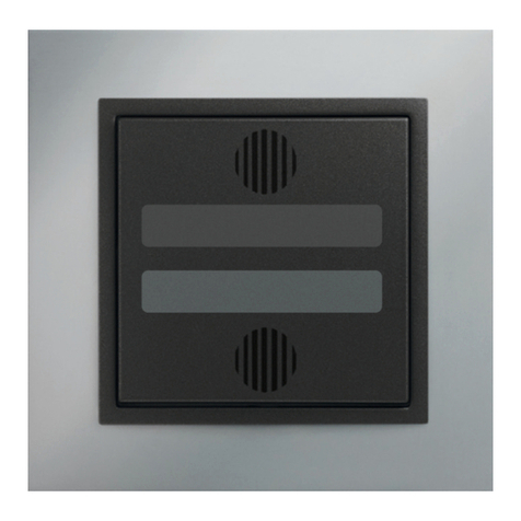
  9. iNels KEY2-01 Simple manual

iNels KEY2-01 Simple manual

CIB +
CIB -
CIB +
CIB -
3111/2-02-001 Rev.: 2
KEY2-01, KEY2-01/R
CZ
Charakteristika / Characteristics
Před instalací přístroje a před jeho uvedením do provozu se seznamte důkladně s montážním návodem k použití. Návod na použití je určen pro
montáž přístroje a pro uživatele zařízení. Návod se musí přiložit k dokumentaci elektroinstalace. Montážní návod naleznete i na webové stránce
www.inels.com. Pozor, nebezpečí úrazu elektrickým proudem! Montáž a připojení mohou provádět pouze pracovníci s příslušnou odbornou
elektrokvalikací při dodržení platných předpisů. Nedotýkejte se částí přístroje, které jsou pod napětím. Nebezpečí ohrožení života. Při
montáži, údržbě, úpravách a opravách je nutné dodržet bezpečnostní předpisy, normy, směrnice a odborná ustanovení pro práci s elektrickým
zařízením. Před zahájením práce na přístroji je nutné, aby všechny vodiče, připojené díly a svorky byly bez napětí. Tento návod obsahuje jen
všeobecné pokyny, které musí být aplikovány v rámci dané instalace.V rámci kontroly a údržby pravidelně kontrolujte (při vypnutém napájení):
- dotažení svorek, - proudění vzduchu.
Zapojení / Connection Menu klávesnice / Keyboard menu
Struktura menu klávesnice / Keyboard menu structure:
EN Control Keyboard
Before the device is installed and operated, read this instruction manual carefully and with full understanding. The instruction manual is
designated for mounting the device and for the user of such device. It has to be attached to electro-installation documentation. The instruction
manual can be also found on a web site www.inels.com. Attention, danger of injury by electrical current! Mounting and connection can be
done only by a professional with an adequate electrical qualication, and all has to be done while observing valid regulations. Do not touch
parts of the device that are energized. Danger of life-threat! While mounting, servicing, executing any changes, and repairing it is essential to
observe safety regulations, norms, directives and special regulations for working with electrical equipment. Before you start working with the
device, it is essential to have all wires, connected parts, and terminals de-energized. This instruction manual contains only general directions
which need to be applied in a particular installation. In the course of inspections and maintenance, always check (while de-energized) if
terminals are tightened and air ow is sucient.
NÁVOD K OBSLUZE / MANUAL INSTRUCTIONS
Zabezpečovací klávesnice
current time / date
aalarm + state of groups 1-8
- logging in
-selection of allowed groups
-state of groups
-alarm ON
-alarm OFF
-restore
-locking all allowed ones
-unlocking all allowed ones
-user’s log-out
aheating
- selection of circuit
-current mode
-current temperature
-minimum setting
-decline setting
-normal setting
-comfort setting
-presentation setting
(comfort until time mark)
-temporary comfort setting (1h)
-control by time program ON
aktuální čas / datum
aalarm + stav skupin 1-8
- přihlášení
-výběr povolených skupin
-stav skupin
-zapnout střežení
-vypnout střežení
-obnovit
-zamknutí všech povolených
-odemknutí všch povolených
-odhlášení uživatele
avytápění
- výběr okruhu
-aktuální režim
-aktuální teplota
-nastavení minima
-nastavení útlumu
-nastavení normálu
-nastavení komfortu
-nastavení prezentace
(komf. do čas. značky)
-nastavení dočasného komfortu (1h)
-zapnutí řízení čas. programem
- Připojuje se na sběrnici systému INELS a jejím prostřednictvím lze
ovládat zabezpečení objektu a monitorovat okruhy vytápění v rámci
systému INELS.
- Pomocí KEY2-01 lze ovládat a monitorovat také světla, vytápění a teploty
v systému INELS.
- Ke sběrnici systému INELS je možno připojit 2 x 32 klávesnic KEY2-01
současně.
- Zabudovaný displej přehledně informuje o stavu zabezpečovacího
systému a stavu okruhu vytápění v rámci systému INELS.
- KEY2-01/R je vybavena bezkontaktním snímačem magnetických médií,
které lze používat pro ovládání systému stejně jako uživatelský kód.
- KEY2-01 is designed to control building security, monitoring of heating
circuits and control lights.
- 2x 32 keybords KEY2-01 can be connected to the bus at the same time.
- Built-in display gives well-arranged information about the status of the
security system and state of heating circuits.
- Keyboard is equipped with contact-less magnetic media reader, which
can be used for system access, in the same way as a user’s code.
Technické parametry / Technical parameters
Všeobecné instrukce / General instructions
CONNECTION INTO THE SYSTEM
Wires of data bus of INELS system are to be connected to a terminal block of unit CIB+ and CIB-, it I not possible to change the terminals. It is essential to use a twisted pair of
wires for data bus. Data communication and supply of units are lead in one pair of wires, it is necessary to observe prole for supply wires with regards to voltage loss on the
lead and maximal consumed output.
CAPACITY AND CENTRAL UNIT
It is possible to connect two independent CIB buses to a central unitCU2-01M. Such connection is done by terminals CIB1+, CIB1- and CIB2+, CIB2-. To each bus, it is possible to
connect up to 32 units, meaning in total you can connect up to 64 units directly to a central unit. Other units can be connected by using units MI2-02M, that generate other CIB
buses. These are connected to a central unit CU by a communication bus TCL2. In total you can connect up to 2 MI2-02M units to one central unit.
COMMUNICATION BUS OF THE SYSTEM
The bus has to be made a cable which is made of twisted pair of wires for data bus of the system with minimal prole of wires 0.5 mm2. Shielded cable needs to be used in case
the bus cables are installed in an environment with a possibility of electromagnetic interference (e.g. in case of side-run with power lead, close to electric machines and devices,
when passing NN through a switchboard etc.).
The bus cable is to be installed in accordance with its mechanic features, that are given by its manufacturer (into a conduit/rail, under a plaster, into a ground, hanging etc.) To
increase its mechanical immunity we recommend installation of the cable into an electro-installation conduit of a sucient prole.
The total length of the bus for 1CU2-01M, or MI2-02M, can be 1100 m (550 m for each bus). Topology of communication bus CIB is free except for circle topology
SUPPLYING THE SYSTEM
To supply system we recommend to use power supplies of company ELKO EP PS-50/27, DR-60-24, PS-100/INELS. The number of power supplies in the system depends on the
sum of rated currents of connected units with a sucient reserve. Installation of higher number of power supplies on a large bus eliminates voltage loss on a long lead. In case
the system contains a system of electric safety signalization, we recommend to use a backed-up power supply with a charger PS-100/INELS in a cover with protective contact.
GENERAL INFORMATION
The unit is able to be operated individually without a central unit but very limited on functions. To use all the functions of the unit it is necessary to connect it to a central unit
CU2-01M, or to a system that already contains this unit and enlarge thus the system functions. All parameters are set by a central unit CU2-01M in software INELS Designer and
Manager.
Installation BUS:
Number of symbols:
Display technology:
Display size:
Font size:
Backlight:
Control codes:
Number of code entry attempts:
Type:
Supported cards:
IC type:
Supply voltage/rated current:
Terminals:
Environment class:
Protection degree:
Operation position:
Installation:
Dimensions:
Weight:
CIB
2 x 16 symbols
COB
99 x 24 mm
4.84 x 9.66 mm
active
4 to 8 symbols
adjustable
RFID 125 kHz ± 6 kHz
ISO Card Unique
Unique 64 Bits RF/64 ASK Manchester
24 V DC/80 mA, from CIB BUS
1 mm2
II. internal general -10..+40 °C
IP 40
any
onto a  at surface
148 x 122 x 32 mm
307 g
ELKO EP, s.r.o.
Palackého 493
769 01 Holešov,Všetuly
TECHNICKÁ PODPORA
E-mail: [email protected]
Mobil: +420 775 371 522
Tel.: +420 573 514 211, +420 573 514 220
Fax: +420 573 514 227
http://www.inels.cz
http://www.elkoep.cz
ELKO EP, s.r.o.
Palackého 493
769 01 Holešov,Všetuly
Czech republic
Technical support: +420 775 371 532
E-mail: [email protected]
Tel.: +420 573 514 211, +420 573 514 220
Fax: +420 573 514 227
http://www.inels.com
http://www.elkoep.com
PŘIPOJENÍ DO SYSTÉMU
Vodiče datové sběrnice systému INELS se připojují na svorkovnici jednotky CIB+ a CIB-, přičemž není možné svorky vzájemně zaměnit. Pro datovou sběrnici je nutno použít
kroucený pár vodičů. Datová komunikace i napájení jednotek jsou vedeny v jednom páru vodičů, přičemž je nutné dodržet průřez pro napájecí vodiče s ohledem na úbytek
napětí na vedení a maximální odebíraný výkon.
KAPACITA A CENTRÁLNÍ JEDNOTKA
K centrální jednotce CU2-01M lze připojit dvě samostatné sběrnice CIB prostřednictvím svorek CIB1+, CIB1- a CIB2+, CIB2-. Na každou sběrnici lze připojit až 32 jednotek, celkově
lze tedy přímo k centrální jednotce připojit až 64 jednotek. Další jednotky lze připojit pomocí jednotek MI2-02M, které generují další sběrnice CIB. Tyto se připojují k jednotce
CU2-01M přes komunikační sběrnici TCL2 a celkem je možno připojit až 2 jednotky MI2-02M k CU2-01M.
KOMUNIKAČNÍ SBĚRNICE SYSTÉMU
Sběrnice musí být provedena kabelem, který obsahuje kroucený pár vodičů pro datovou sběrnici systému s minimálním průřezem vodičů 0.5 mm2. Stíněný kabel je nutné použít
v případě instalace kabelů sběrnice do prostředí s možností elektromagnetických interferencí (např. při souběhu se silovým vedením, v blízkosti elektrických strojů a přístrojů,
při průchodu NN rozvaděčem apod).
Sběrnicový kabel se instaluje v souladu s jeho mechanickými vlastnostmi, které udává výrobce (do trubky/lišty, pod omítku, do země, závěsný apod.) Pro zvýšení mechanické
odolnosti kabelů doporučujeme vždy kabel instalovat do elektroinstalační trubky vhodného průměru.
Celková délka vedení sběrnice pro 1CU2-01M , popřípadě MI2-02M, může být 1100 m (550 m pro každou sběrnici).
Topologie komunikační sběrnice CIB je volná s vyjímkou topologie kruhu.
NAPÁJENÍ SYSTÉMU
K napájení jednotek systému doporučujeme použít napájecí zdroje ELKO EP PS-50/27, DR-60-24, PS-100/INELS. Počet napájecích zdrojů v systému je dán součtem jmenovitých
proudů připojených jednotek s odpovídající rezervou. Větší počet zdrojů na rozsáhlé sběrnici eliminuje také úbytek napětí na dlouhém vedení. Pokud je v instalaci použit systém
elektrické zabezpečovací signalizace, doporučujeme použít zálohovaný zdroj PS-100/INELS v krytu s ochranným kontaktem.
VŠEOBECNÉ INFORMACE
Jednotka je schopna pracovat jako samostatný prvek bez centrální jednotky jen ve velmi omezeném rozsahu svých funkcí. Pro plnou využitelnost jednotky je nutné aby jednotka
byla napojena na centrální jednotku systému CU2-01M, nebo na systém, který tuto jednotku již obsahuje, jako jeho rozšíření o další funkce systému.
Všechny parametry jednotky se nastavují přes centrální jednotku CU2-01M v software INELS Designer and Manager.
CIB
2 x 16 znaků
COB
99 x 24 mm
4.84 x 9.66 mm
aktivní
4 až 8 znaků
nastavitelný
RFID 125 kHz ± 6 kHz
ISO Card Unique
Unique 64 Bits RF/64 ASK Manchester
24 V DC/80 mA, ze sběrnice CIB
1 mm2
II. vnitřní všeobecné -10.. +40 °C
IP 40
libovolná
na rovnou plochu
148 x 122 x 32 mm
307 g
Instalační sběrnice:
Počet znaků:
Technologie displeje:
Velikost displeje:
Velikost fontu:
Podsvícení:
Ovládací kódy:
Počet pokusů zadání kódu:
Typ:
Podporované karty:
IC Type:
Napájecí napětí/jm. proud:
Svorkovnice:
Třída prostředí:
Stupeň krytí:
Pracovní poloha:
Instalace:
Rozměry:
Hmotnost:
This manual suits for next models

1

Other iNels Controllers manuals

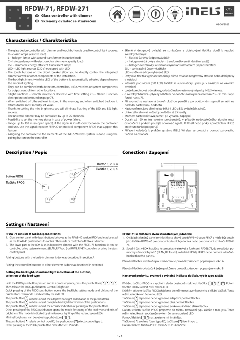
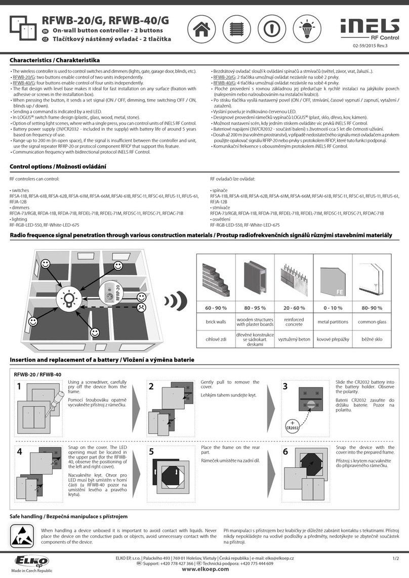
iNels RFDW-71 User manual

iNels

iNels RFDW-71 User manual

iNels SOPHY2 User manual

iNels

iNels SOPHY2 User manual

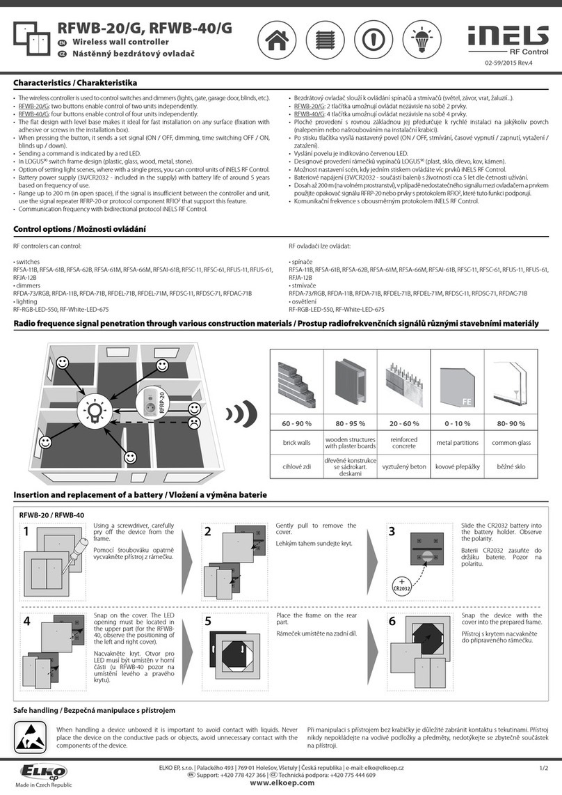
iNels RFWB-20/G User manual

iNels

iNels RFWB-20/G User manual

iNels SA3-01B User manual

iNels

iNels SA3-01B User manual

iNels RFOWB-20 User manual

iNels

iNels RFOWB-20 User manual

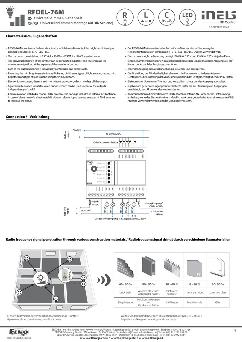
iNels RFDEL-76M User manual

iNels

iNels RFDEL-76M User manual

iNels PS-30/24 Quick guide

iNels

iNels PS-30/24 Quick guide

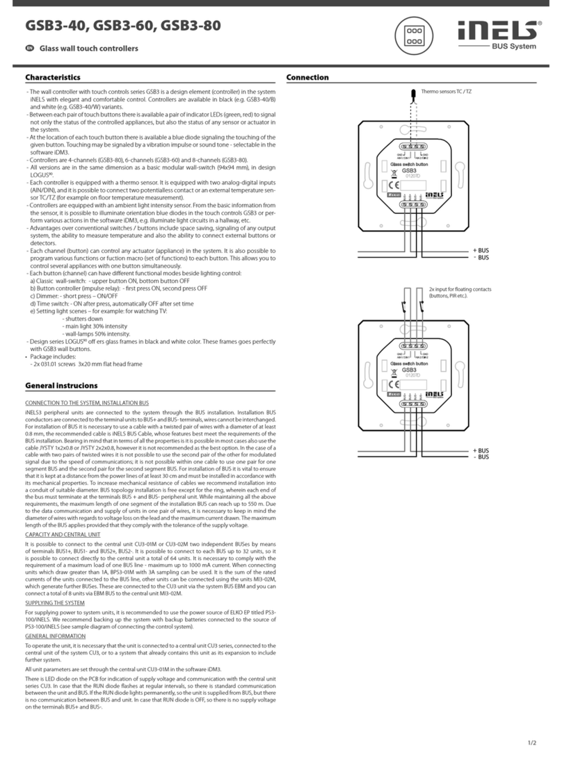
iNels GSB3-40 User manual

iNels

iNels GSB3-40 User manual

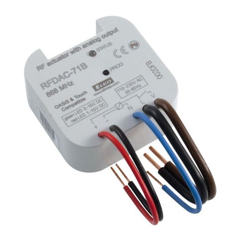
iNels RFDA-73M/RGB User manual

iNels

iNels RFDA-73M/RGB User manual

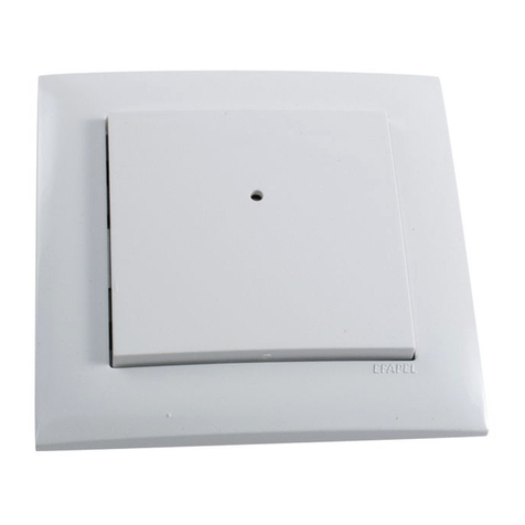
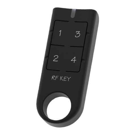
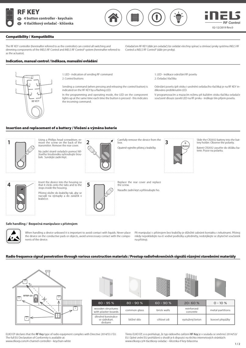
iNels RF KEY User manual

iNels

iNels RF KEY User manual

iNels RFWB-20/G User manual

iNels

iNels RFWB-20/G User manual

iNels SA3-02M Instruction manual

iNels

iNels SA3-02M Instruction manual

iNels RF KEY User manual

iNels

iNels RF KEY User manual

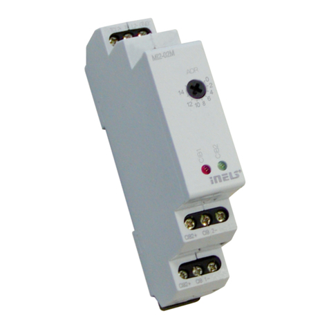
iNels EA3-022M User manual

iNels

iNels EA3-022M User manual

iNels SA2-02B Simple manual

iNels

iNels SA2-02B Simple manual

iNels IDRT3-1 User manual

iNels

iNels IDRT3-1 User manual

iNels WTC2-21 Simple manual

iNels

iNels WTC2-21 Simple manual

iNels RFWB-20/G User manual

iNels

iNels RFWB-20/G User manual

iNels SA3-012M User manual

iNels

iNels SA3-012M User manual

iNels SA2-04M Simple manual

iNels

iNels SA2-04M Simple manual

iNels RF KEY - 40 User manual

iNels

iNels RF KEY - 40 User manual

iNels JA2-02B User manual

iNels

iNels JA2-02B User manual

iNels RF KEY User manual

iNels

iNels RF KEY User manual

iNels SA2-01B Simple manual

iNels

iNels SA2-01B Simple manual

Popular Controllers manuals by other brands

Afag Electric Slide Series Translation of the original operating manual

Afag

Afag Electric Slide Series Translation of the original operating manual

Toshiba BMS-CT1280E owner's manual

Toshiba

Toshiba BMS-CT1280E owner's manual

PCS TC50 Series Quick start up guide

PCS

PCS TC50 Series Quick start up guide

infobit HDV-CTL100 user manual

infobit

infobit HDV-CTL100 user manual

DSE DSE5510 operating manual

DSE

DSE DSE5510 operating manual

Suzhou MONARCH Control Technology Co., Ltd. NICE3000 New user manual

Suzhou MONARCH Control Technology Co., Ltd.

Suzhou MONARCH Control Technology Co., Ltd. NICE3000 New user manual

Condair Links Series Installation and operation

Condair

Condair Links Series Installation and operation

Sutter Instrument MPC-200 Operation manual

Sutter Instrument

Sutter Instrument MPC-200 Operation manual

HP ProCurve MSM710 installation guide

HP

HP ProCurve MSM710 installation guide

Omron SYSMAC 3G8F7-CLK13-E Operation manual

Omron

Omron SYSMAC 3G8F7-CLK13-E Operation manual

Cosytoes Mirage Timerstat instruction manual

Cosytoes

Cosytoes Mirage Timerstat instruction manual

AirCom 234KM operating manual

AirCom

AirCom 234KM operating manual

NXP Semiconductors MC9S12ZVH64 Reference manual

NXP Semiconductors

NXP Semiconductors MC9S12ZVH64 Reference manual

TrickleStar TS2301 quick start guide

TrickleStar

TrickleStar TS2301 quick start guide

White Rodgers UNIVERSAL INTEGRATED FURANCE CONTROL... installation instructions

White Rodgers

White Rodgers UNIVERSAL INTEGRATED FURANCE CONTROL... installation instructions

Infineon TC3X7 ADAS manual

Infineon

Infineon TC3X7 ADAS manual

Trox Technik VFL Series manual

Trox Technik

Trox Technik VFL Series manual

Smartgen HMAT880 user manual

Smartgen

Smartgen HMAT880 user manual

manuals.online logo
manuals.online logoBrands
  • About & Mission
  • Contact us
  • Privacy Policy
  • Terms and Conditions

Copyright 2025 Manuals.Online. All Rights Reserved.