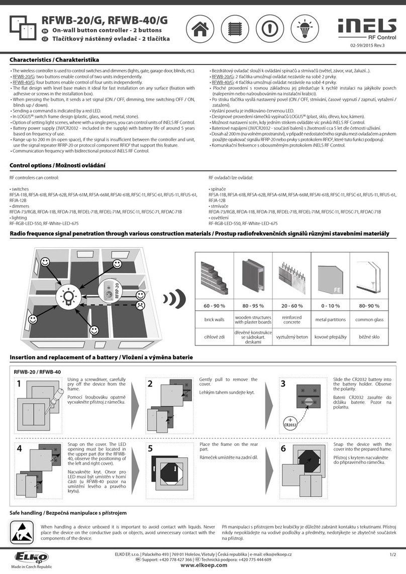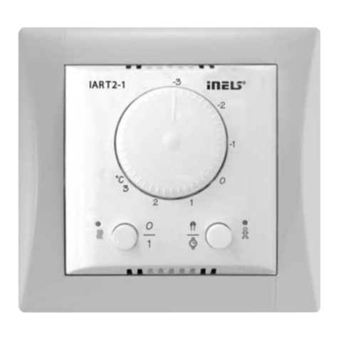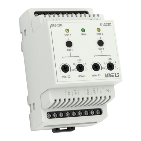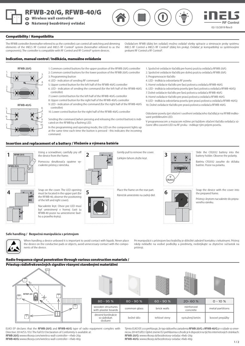
ГОЛОСОВЕ УПРАВЛЕНИЕ
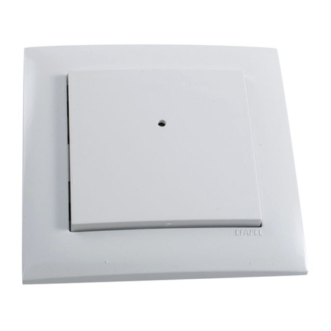
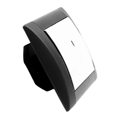
Верх комфорта системы INELS . Встроенный голосовой процессор может распознать до 64 пользовательских команд.
ТЕРМОМЕТРИЯ
Встроенный температурный сенсор регистрирует температуру в данном помещении. Это можно в последствии применить для регуляции отопления.
Снятие показаний интенсивности окружающего освещения
Встроенный сенсор фиксирует показания интенсивности окружающего освещения на основании этих данных автоматически может включить освещение или опустить жалюзи.
ПРИЁМНИК ИНФРАКРАСНОГО ИК СИГНАЛА
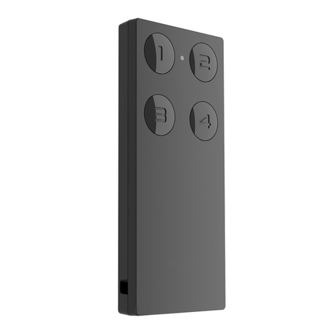
Встроенный приемник ИК сигнала позволяет принять приказ от большинства пультов ДУ, которые применяются для управления бытовой электроникой (TV, DVD, HIFI, VIDEO …).
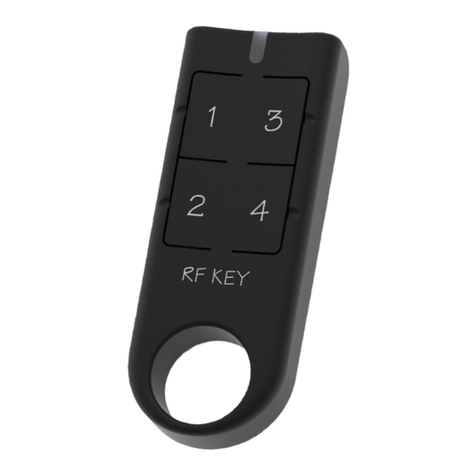
Кнопками пульта ДУ, которые не используются, можно управлять разными исполнителями подключенных к системе. В рамках аксессуаров поставляются универсальные пульты
дистанционного управления, которые можно использовать не только для управления INELS оборудования, но и для управления домашней электроникой.
ПЕРЕДАТЧИК ИНФРАКРАСНОГО ИК СИГНАЛА
Встроенный передатчик IR сигнала, наоборот, позволяет предавать приказы и управлять оборудованием как классический пульт дистанционного управления. Условием является
настройка управляемого оборудования на блок (прямая видимость).
КНОПОЧНЫЙ БЛОК УПРАВЛЕНИЯ
В верхней и нижней части передней панели расположены микрокнопки (также как и у контроллера WSB), которые могут управлять разными пускателями (исполнителями),
объединенными в системе.
4 УНИВЕРСАЛЬНЫХ ВХОДА
Sophy2 позволяет присоединить до 4 блок-контактов от внешних приборов (например, PIR сенсор, стандартная розетка или выключатель), объединенных в системе.
Общие инструкции / General instructions
ПОДКЛЮЧЕНИЕ К СИСТЕМЕ
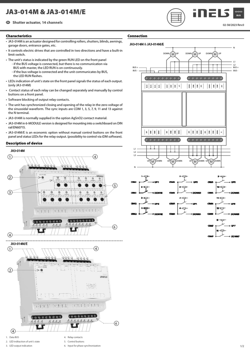
Провода информационной шины системы INELS подключаются к клеммам устройства CIB+ a CIB-, причём клеммы нельзя взаимно заменять. Для информационной шины необходимо
использовать витую пару. Информационный обмен и питание устройства осуществляются через одну пару проводов, причём необходимо соблюсти сечение проводов питания с
учётом потери напряжения на проведение и максимальную потребляемую мощность.
ЁМКОСТЬ И ЦЕНТРАЛЬНЫЙ ЭЛЕМЕНТ
К центральному элементу CU2-01M можно подключить две самостоятельные шины CIB посредством клемм CIB1+, CIB1- и CIB2+, CIB2-. К каждой шине можно подключить до 32
элементов, таким образом, всего к центральному элементу можно подключить до 64 элементов. Следующие элементы можно подключить посредством MI2-02M, которые генерируют
следующие шины CIB. Они подключаются к CU через коммуникационную шину TCL2 . Всего к центральному элементу можно подключить до 2 элементов MI2-02M.
КОММУНИКАЦИОННЫЕ ШИНЫ СИСТЕМЫ
В качестве шины должен быть использован кабель, состоящий из витой пары с минимальным диаметром проводов 0.5 mm2. При размещении кабеля шины в среде с возможной
электромагнитной интерференцией (напр. при близком расположении силовых кабелей, вблизи электрических станков, при прохождении NN распределителей и т.д.) необходимо
использовать экранированный кабель. Кабель шины располагается в соответствии с его механическими свойствами, которые указывает производитель (в трубку/рейку, под штукатурку,
в землю, подвесное и т.д.) Для повышения механической стойкости кабеля рекомендуем помещать его в электромонтажную трубку подходящего диаметра. Общая протяжённость шины
для CU2-01M, или MI2-02M, может быть 1100 м (550 м для каждой шины).Топология коммуникационной шины CIB произвольная за исключением топологии„кольцо„.
ПИТАНИЕ СИСТЕМЫ
Для питания элементов системы рекомендуем использовать источники питания ELKO EP PS-50/27, PS-100/INELS. количество источников питания в системе дано суммой номинальных
токов подключенных элементов с соответствующим резервом. Большее количество источников питания на разветвлённой шине также компенсирует потерю напряжения на длинной
проводке. если в системе использована электронная охранная сигнализация, рекомендуем использовать резервный источник питания PS-100/INELS в корпусе с защищённым
контактом.
ОБЩАЯ ИНФОРМАЦИЯ
Устройство способно работать самостоятельно без подключения к центральному элементу только в узком диапазоне своих функциональных возможностей. Для полнеценного
использования элемента необходимо, чтобы он был подключен к центральному элементу CU2-01M, или к системе, которая этот элемент уже содержит, в качестве расширения ей
функциональности. Все параметры устройства настраиваются через центральный элемент CU2-01M в программе INELS Designer and Manager.
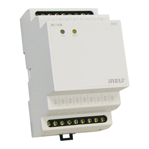
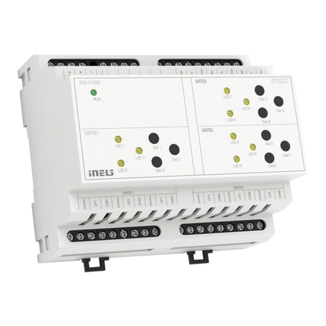
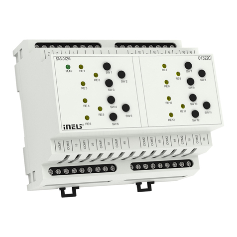
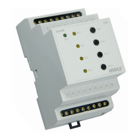
На лицевой панели устройства находятся LED диоды, указывающие состояние напряжения питания, коммуникации с центральным элементом CU2-01M и индикации выходов
элемента.
CONNECTION INTO THE SYSTEM
Wires of data bus of INELS system are to be connected to a terminal block of unit CIB+ and CIB-, it I not possible to change the terminals. It is essential to use a twisted pair of wires for data
bus. Data communication and supply of units are lead in one pair of wires, it is necessary to observe prole for supply wires with regards to voltage loss on the lead and maximal consumed
output.
CAPACITY AND CENTRAL UNIT
It is possible to connect two independent CIB buses to a central unitCU2-01M. Such connection is done by terminals CIB1+, CIB1- and CIB2+, CIB2-. To each bus, it is possible to connect up to
32 units, meaning in total you can connect up to 64 units directly to a central unit. Other units can be connected by using units MI2-02M, that generate other CIB buses. These are connected
to a central unit CU by a communication bus TCL2. In total you can connect up to 2 MI2-02M units to one central unit.
COMMUNICATION BUS OF THE SYSTEM
The bus has to be made a cable which is made of twisted pair of wires for data bus of the system with minimal prole of wires 0.5 mm2. Shielded cable needs to be used in case the bus cables
are installed in an environment with a possibility of electromagnetic interference (e.g. in case of side-run with power lead, close to electric machines and devices, when passing NN through
a switchboard etc.).
The bus cable is to be installed in accordance with its mechanic features, that are given by its manufacturer (into a conduit/rail, under a plaster, into a ground, hanging etc.) To increase its
mechanical immunity we recommend installation of the cable into an electro-installation conduit of a sucient prole.
The total length of the bus for 1CU2-01M, or MI2-02M, can be 1100 m (550 m for each bus). Topology of communication bus CIB is free except for circle topology.
SUPPLYING THE SYSTEM
To supply system we recommend to use power supplies of company ELKO EP PS-50/27, DR-60-24, PS-100/INELS. The number of power supplies in the system depends on the sum of rated
currents of connected units with a sucient reserve. Installation of higher number of power supplies on a large bus eliminates voltage loss on a long lead. In case the system contains a system
of electric safety signalization, we recommend to use backed-up power supply PS-100/INELS in cover with protective contact.
GENERAL INFORMATION
The unit is able to be operated individually without a central unit but very limited on functions. To use all the functions of the unit it is necessary to connect it to a central unit CU2-01M, or to
a system that already contains this unit and enlarge thus the system functions. All parameters are set by a central unit CU2-01M in software INELS Designer and Manager. On the front panel
there are LED diodes to indicate presence of supply voltage, communication with a central unit CU2-01M.
OOO“ЭЛКО ЭП Ру”
2-я Тверская-Ямская 31/35
125147 Москва
Tel.: +7 499 978 7641
Fax: +7 499 978 7742
http://www.inels.com
http://www.elkoep.ru
ELKO EP, s.r.o.
Palackého 493
769 01 Holešov,Všetuly
Czech republic
Technical support: +420 775 371 532
Tel.: +420 573 514 211, +420 573 514 220
Fax: +420 573 514 227
http://www.inels.com
http://www.elkoep.com
VOICE CONTROL
Represents the top of comfort of INELS system. Built-in voice processor is able to detect up to 64 voice commands.
TEMPERATURE MEASURING
Built-in thermo sensor measure temperature in a designed area, it can be used for heating and cooling regulation.
AMBIENT LIGHT INTENSITY DETECTION
Built-in sensor measures ambient light intensity and on the basis of this information it is automatically able to control lighting or Venetian blinds.
INFRARED IR SIGNAL RECEIVER
Built-in IR receiver can receive commands from most remote controls, which are used for home electronics (TV, DVD, HIFI, VIDEO …), which are using format codes RC5, NEC, SRCS.
As an accessory we can provide a universal remote controller which can be used for INELS devices, as well as other home electronics.
INFRARED IR SIGNAL TRANSMITTERS
Built-in IR signal transmitter enables transmittion of commands and controlling of devices as a standard remote control. Correct direction setting and easy signal access to the unit, is necessary.
Switch controllerIn upper and lower part of control area (front cover) there are micro-switches (as well as on WSB controllers). These can control various actuators (appliances) connected to the
system.
4 UNIVERSAL INPUTS
Sophy2 enables connection of up to 4 potentialless contacts from external devices ( PIR sensors, standard switch or button etc.).
