manuals.online logo
Brands
  1. Home
  2. •
  3. Brands
  4. •
  5. Jaga
  6. •
  7. Heater
  8. •
  9. Jaga BRIZA 041 User manual

Jaga BRIZA 041 User manual

1
BRIZA EC
E / 27200.23700029 - 7 september 2016 3:49 PM - Jaga N.V.E
/
27200.2
3
700029
-
7 september 2016
3
:49 PM - Jaga N.
V.
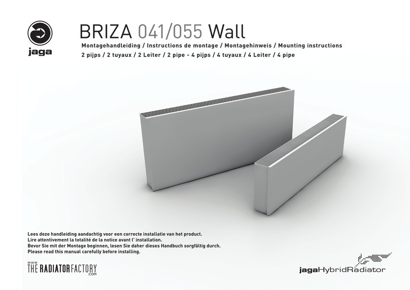
Installation Instructions Briza 2 pipe & 4 pipe
BRIZA 041/055 WALL / CEILING
BRIZA 038/052 BUILT-IN WALL / CEILING
Deze handleiding is beschikbaar in het NEDERLANDS:
http://theradiatorfactory.com/briza_benl
Ce manuel est disponible en FRANÇAIS:
http://theradiatorfactory.com/briza_befr
http://theradiatorfactory.com/briza_fr
Dieses Handbuch ist erhältlich in DEUTSCH:
http://theradiatorfactory.com/briza_de
This manual is available in ENGLISH:
http://theradiatorfactory.com/briza_e
http://theradiatorfactory.com/briza_e_imperial
Please read this manual carefully before instal-
ling.
Installation must only be carried out by skilled
technicians. The unit must be installed according
to national or local standards in force at the time
of installation. Always use personal protective
equipment.
NBN EN60335-1 based on EN60335-1-2002
+ a11:2004 + a1:2004 + a12:2006 + a2:2006 +
a13:2008 + A14:2010 + A15:2011
NBN EN 60335-2-80 based on EN 60335-2-
80:2003 + A1:2004 + A2:2009
2BRIZA EC E / 27200.23700029 - 7 september 2016 3:49 PM - Jaga N.V.
Instruction for installation, handling and storage
Packaging and components
Follow these instructions to remove the packaging:
• check for any visible damage
• open the packaging
• check if the manual is in the package
• remove the packaging material and dispose it in the appropriate collection points or recycling facili-
ties, in compliance with the local regulations
SAFEGUARD THE ENVIRONMENT
Dispose of the packaging materials in compliance with the national or local legislation.
DANGER!
Do not leave the packaging within reach of children.
Handling guidelines:
DANGER!
Movement of the unit must be performed with care, in order to avoid damage to the external structure
and to the internal mechanical and electrical components. Also make sure that there are no obstacles
or people along the route, in order to prevent the risk of impact, crushing or tipping the lifting device.
Always use personal protective equipment.
All the operations listed below must be carried out in accordance with current health and safety regu-
lations, with reference to the equipment used as well as the procedures followed. Before commencing
handling operations, ensure that the lifting device has the required capacity for the unit in question.
The units can be moved or lifted by hand or by means of a suitable truck. If the unit weighs more than 30
kg and is to be handled manually, this must be carried out by two persons: however, it is recommended
to use a truck. If several units need to be moved at the same time, it is advisable to put the units in a
container and lift them by means of a crane or similar vehicle.
Storage conditions:
Packaged units can be stored by stacking a maximum of four on top of each other and must be stored
in a dry area.
Technical spaces and positioning:
IMPORTANT!
Incorrect positioning or installation of the unit may amplify noise levels and vibrations generated dur-
ing operation.
User
Device description:
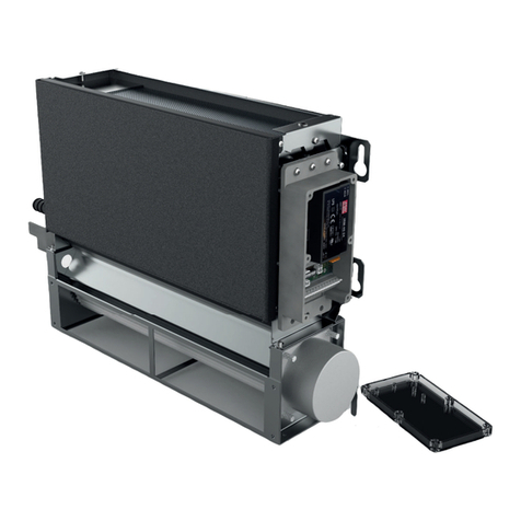
Jaga Briza EC are fan coils for the treatment of air in indoor environments.
The units comply with the following Directives:
• 2006/42/EC Machinery Directive
• low voltage Directive 2006/95/EC
• electromagnetic compatibility Directive 2004/108/EC
• regulation n.327/2011/UE implementing Directive 2009/125/EC ERP
Declared conditions of use:
The unit is not designed to be installed in rooms used for laundry purposes (IEC EN 60335-2-40).
• the unit is only to be installed in domestic or similar environments.
• it is prohibited to insert objects through the air inlet and outlet vents.
IMPORTANT!
• the unit will function correctly only if the instructions for use are strictly followed, if the specified
clearances are complied with during installation, as well as the use restrictions indicated in this
manual.
• an installation that does not include the recommended free spaces, resulting in difficulty in mainte-
nance and reduced performance
• pay the utmost attention to the signs and symbols located on the appliance.
Identification of the unit:
The units are equipped with a label sharing the serial number plate on the right side of the unit (on the
left if the connections are on the right side of the unit).
Functioning limits:
Installation that does not meet the operating limits specified relieves Jaga N.V. from liability concern-
ing damage to objects and persons.
• mains voltage 230 V 1 ph 50 Hz.
• maximum water inlet temperature: 3÷90°c.
• maximum exchanger pressure: 6 bar.
• power supply voltage: 24 V ±10%
Information regarding unintended use:
The unit has been designed and constructed solely and exclusively to function as an air treatment ter-
minal unit with ducting or panelling; any other use is strictly forbidden. Installing the Jaga Briza EC in
an explosive environment is prohibited.
Decommissioning:
When the unit is not used for long periods of time, it must be disconnected from the mains by opening
the mains switch of the system, set in place by the installer.
If the unit is not used during the winter period, the water contained in the system may freeze. All the wa-
ter in the circuit must be drained on time. Alternatively, a suitable quantity of anti-freeze liquid should
be mixed with the water.
Restart after prolonged shutdown:
Before starting up again:
• clean or replace the air filter.
• clean the exchanger.
• clean or unclog the drain of the condensate tray.
• bleed the water system.
• it is advisable to run the unit at maximum speed for several hours.
3
BRIZA EC
E / 27200.23700029 - 7 september 2016 3:49 PM - Jaga N.V.
Maintenance
ATTENTION!
• maintenance must only be carried out by qualified technicians, qualified to work on air-conditioning
and refrigeration systems. Use suitable work gloves.
• do not insert sharp objects through the air flow or intake grilles
Special note:
Maintenance and cleaning of the grate:
• a dirty grate obstructs the flow of air to the ventilator, so clean the grate at regular intervals, depend-
ing on the usage and function of the room. The grate must not be dismantled for maintenance and can
simply be cleaned with a vacuum cleaner
Cleaning the appliance:
• always disconnect and lock out power before installing or servicing the fan !!
• cleaning at regular interval is important, (at least once a year), depending on the use and function of
the room
• clean with a soft cloth dampened with water and a little dish soap. Do not use products based on
solvents and detergents.
Routine maintenance
Monthly:
Checking the air filters
The level of pollution of the filters
must be checked at the beginning of
the season when the unit will be used
and generally every month.
Every 6 months:
Check the condition of the exchanger
and condensate drain. If necessary:
• remove any debris from the finned
surface to clear the air passage
• remove the dust using compressed
air
• gently wash with water and brush
gently
• dry using compressed air
• keep the condensate drain free from
any obstructions that may prevent
normal water flow
Checking whether there is air in the water system.
1. start the system for a few minutes
2. stop the system
3. loosen the vent screw on the inlet collector and bleed it
4. repeat the operation several times until air is no longer
released from the system.
End of season
Draining the water system (for all exchangers).
It is advisable to drain the water from the system at the end
of the season in order to prevent breakage due to freezing.
Electrical circuit
The following operations are recommended to perform main-
tenance on the electrical circuit:
• check the unit power consumption using a clip-on meter
and compare the reading with the values shown in the
documentation;
• inspect and check that the electrical contacts and relative
terminals are tightened correctly.
Anti-freeze protection
IMPORTANT!
Mixing the water with glycol modifies the performance of the unit. Pay attention to the safety instruc-
tions on the package regarding glycol.
If the unit is not used during the winter period, the water contained in the system may freeze. All the
water in the circuit must be drained on time. If draining the system is to complex, a suitable amount of
antifreeze liquid can be mixed with the water.
Warning: user safety
This appliance is not intended for use by persons (including children) with reduced physical, sensory or
mental capabilities, or lack of experience and knowledge, unless they have been given supervision or
instruction concerning use of the appliance by a person responsible for their safety.
Children should be supervised to ensure that they do not play with the appliance.
Always use the mains switch to isolate the unit from the mains before carrying out any maintenance work
on the unit, even if it is for inspection purposes only. Make sure that no one supplies power to the unit
accidentally; lock the master switch in zero position.
Please follow these instructions carefully in order to allow for an error-free installation and a carefree
use.
Entitlement to warranty is cancelled in case of:
• errors or damage resulting from not following the assembly, cleaning or user instructions supplied by
the manufacturer,
• wrong, improper and/or irresponsible use or treatment of the device,
• wrong or incompetent repairs and defects due to external factors,
• self-applied changes to the device.
• equipment that is built in, in a way that it cannot be reached normally.
If you have any questions or complaints, please contact your supplier or installer.
The copyright of these instructions is the property of the company Jaga Inc.
Page INDEX
2 User / Instruction for installation, handling and storage
3 Maintenance / Warning: use & safety
4 Composition
5 Mounting dimensions / Acoustic isolation
6 Dimensions / Dimensions hydraulic connections
7 Dimensions / Dimensions hydraulic connections
8 Installation instructions / Installation guidelines
9 Installation hydraulic and electrical connections
10 Connection to home automation / Option condensate drain tray
11 Option valve sets / Option room thermostats
12 Instructions for start-up / Instructions to dismantle the unit and dispose of
hazardous substances
4BRIZA EC E / 27200.23700029 - 7 september 2016 3:49 PM - Jaga N.V.
Composition Briza Built-In Wall& Ceiling Composition Briza Wall & Ceiling surface
1Dynamic Low-H2O heat exchanger 6Mounting holes = Composition Briza Built-In +
2Condensate drain model Built-In Ceiling 7Tangential fan 10 Condensate drain pan wall model is included as standard
3Additional drain pan for cooling, model only for Built-In ceiling 8Frame made of reinforced galvanised steel plate 11 Dynamic outlet grille
4Hydraulic connection 2-pipe 3/4”G (Eurocone) standard on the LHS 9Electrical connection standard on the RHS 12 Casing
5Stainless steel grate
C
omposition Briza Built-In Wall& Ceiling
C
omposition Briza Wall & Ceiling sur
f
1
Dynam
i
c Low-H
2
O
heat exchanger
6
Mount
i
ng holes =
C
omposition Briza Built-In +
2
Condensate drain model Built-In Ceilin
g
7
Tangential
f
a
n
10
Condensate drain
p
an wall model is include
d
3
Additional drai
n p
an for cooli
ng,
model only for Built-In ceili
ng
8
F
rame made of reinforced
ga
lvanised steel
pla
te 1
1
Dynamic outlet
gri
lle
4Hydraulic connection 2-
p
i
p
e 3
/
4”G
(
Eurocone
)
standard
o
n th
e
LH
S
9
El
ec
tr
ica
l
co
nn
ec
t
io
n
s
t
a
n
da
r
d
o
n th
e
RH
S
1
2
C
asing
5
Stainless steel grat
e











OPTION
Dynamic outlet grille 11
ATTENTION!
The direction of the air flow is determined by the shape of the
grille fins. Fit the grille so that the airflow is sent into the room.
5
BRIZA EC
E / 27200.23700029 - 7 september 2016 3:49 PM - Jaga N.V.
Mounting dimentions Built-In Ceiling Acoustic isolation
Respect the free space around the unit as shown: Insulation against airborne noise
Sound is reflected by hard materials. Soft, porous substances are
best suited to absorbing airborne sound.
Contact sound insulation
Sound travels very easily in hard materials. Contact sound insula-
tion will largely depend on this:
A. Quality of the placement<
Contact points:
•make sure that sound- and/or mechanical vibrations cannot be
transferred between different elements, e.g. between the built-in
heaters and a metal carrier, through pipes, along air ducts etc.
Hollow acoustic spaces:
• where air can travel, so can sound. Isolate the built-in heaters
in hollow acoustic spaces. Avoid cavities between insulation and
pipes. These form small resonance boxes. Avoid cavities along air
ducts (the acoustic effect cannot be predicted for this).
≥15 ≥15
max. 230 cm max. 230 cm
≥15
≥15
Mounting dimentions Built-In Wall ATTENTION
≥10
≥15
≥15 ≥15
The unit must remain accessible for maintenance
Free spaces and installation:
IMPORTANT!
Incorrect positioning or installation of the unit may
amplify noise levels and vibrations generated during
operation.
6BRIZA EC E / 27200.23700029 - 7 september 2016 3:49 PM - Jaga N.V.
Briza 041 Wall / Ceiling: Dimensions / Dimensions hydraulic connections
Briza 038 2-pipe 4-pipe
A
min. 10
13
L
35.2
41
3
20.8
16.5 8.5
7.3
4.5
2.8
25
2.8
3.9
25
812.5
812.5
7.8
3.8
A
A
R
R
10
2.3
Briza 055 Wall / Ceiling: Dimensions / Dimensions hydraulic connections
Briza 052 2-pipe 4-pipe
L
16.5 8.5
13
25
13
25
48.2
3
20.8
min. 10
55
3.9
7.8
3.8
8.3
4.6
R
13
A
A
R
10
2.3
Model T 1 T 2 T 3 T4 A= supply
R= Return
• Wall unts standard delivery with condensate drain pan
• Ceiling units standard delivery without condensate drain pan
L (cm) 75 95 125 145
7
BRIZA EC
E / 27200.23700029 - 7 september 2016 3:49 PM - Jaga N.V.
Briza 038 Built-In Wall / Ceiling: Dimensions / Dimensions hydraulic connections
Briza 038 2-pipe 4-pipe
A
min. 10
12
L
35.2 38
3
20.8
7.3
4.5
2.8
25
10
2.8
3.9
25
2.3
8
87.5 7.5
7.8
3.8
A
A
R
RA
Briza 052 Built-In Wall / Ceiling: Dimensions / Dimensions hydraulic connections
Briza 052 2-pipe 4-pipe
10
2.3
L
13
25
13
25
48.2
3
20.8
min. 10
52
3.9
7.8
3.8
8.3
4.6
R
12
A
A
R
Model T 1 T 2 T 3 T4 A= supply
R= Return
• Built-In Wall units standard delivery with condensate drain pan
• Built-In Ceiling units standard delivery without condensate drain pan
• drain pan option: only for Briza Built-In Ceiling
L (cm) 52 72 102 122
8BRIZA EC E / 27200.23700029 - 7 september 2016 3:49 PM - Jaga N.V.
1Installation instructions 2Installation guidelines
• the installation must only be carried out by skilled technicians,
qualified for working on air conditioning and cooling systems. In-
correct installation could cause the unit to run badly, with a con-
sequent deterioration in performance.
• the unit must be installed according to national or local standards
in force at the time of installation
• the unit must remain accessible for maintenance
• always use personal protective equipment
• mark the fastening points on the wall or ceiling using those on the
unit or according to the dimensions specified in this guide.
• the type of wall determines what type of screw or plug should be
used
1Disassemble the casing Disconnect the grille security a
aRemove the grille. Only for ceiling surface mounted:
bRemove the screws above and below the unit. • unscrew the grille security
• slide the clamp plates to the outer side of the grille
cRemove the casing. Further technical installation and connection (s) is identical for all
Briza Built-In and Surface units.
• respect the free space around the unit as shown in the manual
• insulate the valves and connections and pipes with 10 mm thick
anti-condensation material or install the auxiliary pans
• keep a slight tilt towards the condensate drain to help the water
drain
OPTION →
9
BRIZA EC
E / 27200.23700029 - 7 september 2016 3:49 PM - Jaga N.V.
Electrical connection
c
ATTENTION!
The electrical connection of the unit must be carried out by quali-
fied personnel, in compliance with the regulations applicable in the
country where the unit is installed.
Non-conforming electrical connections releases Jaga N.V. from
liability concerning damage to objects and persons.
• check that the voltage and frequency of the grid corresponds to
the information on the registration plate of the device
• that the available installed power is sufficient for running the
equipment
• if the unit is mounted on a metal surface, the earth connection
must be installed in compliance with local regulations. The earth
conductor must be longer than the other conductors so that it is
the last one to release in the event the connection comes loose.
• that the supply cables are of adequate section for the maximum
current required.
13
2
0..10 VDC
SUPPLY
MOTOR
24 VDC
0 VDC


3Mount the casing
aPosition the casing
Attach the screws above and below the unit
bPlace the grille
ATTENTION! The direction of the air flow is determined by the shape
of the fins of the grille.
Only for Briza Ceiling (with casing)
• slide the clamping plates to the inner side of the grate
• assure the grille security
Hydraulic connection
b
ATTENTION!
It is very important for the water connections to be installed with
care by qualified personnel.
ATTENTION!
Position the drain pipes without mechanical stress on the drain
connection of the unit.
Hydraulic connections:
Connect the unit to the hydraulic system with the indicated inlet/
outlet connections as shown on page 7. Make sure the connections
are air tight with a sealant.
• all heat exchangers (including the additional one), are equipped
with an air vent near the top connection, and a water drain near
the lower connection.
• heat exchangers can be partially drained; it is recommended to
bleed air inside the coil to be drained completely.
Setting up the condensate drain:
The condensation drainage system must be set up with an ade-
quate inclination to make sure the water drain properly. When not
using the condensate drain pan, the outlet duct must be connected
directly to the condensation collection. In this case, the hydraulic
and the valves must be used for cooling water surely be insulated
against condensation.
Stench trap (sifon):
The condensate drain must be fitted with a stench trap:
100 mm
50 mm
Always set up or install a plug for cleaning in the lower part of the
siphon in order to allow quick disassembly.
Once installation is complete:
• bleed the air contained in the circuit
• make sure that there are no water leaks
• insulate the valves and connections and pipes with 10 mm thick
anti-condensation material or install the auxiliary pans
• pour water into the condensate collection pan and check if the liq-
uid is drained properly. Otherwise, check the inclination and look
for possible blockages.
10 BRIZA EC E / 27200.23700029 - 7 september 2016 3:49 PM - Jaga N.V.
Option condensate drain tray for Briza Built-In Ceiling
Option: condensate drain tray Option: condens water-level sensor
• Built-In Ceiling units: standard delivery without condensate drain tray
• drain pan option: only for Briza Built-In Ceiling
• switch features: Normally closed (NC)
• white polypropylene with silicone O-ring.
• condensation water level sensor
Ø 20
128 95
30
50
295
215
Briza H38
Briza H52
≥15
2.8
Briza H38
Condensate drain tray
L 215 Code: 5127.00010001 Briza H38
Liquid water level sensor
for
condensate drain tray
Code: 5127.00010003
Briza H52
Condensate drain tray
L 295 Code: 5127.00010002 Briza H52
E316052
Type switch Max.
switching
current
Max.
switching
voltage
Max.
temperature
Max. pressure
10 W (NC) 0.25 A 100 VDC
80° C / 194°F
25 PSIG
0...10 V Connection to home automation
+ 0...10VDC
- 0VDC
0..10V
Domotica
230 VAC
LN
DC LO
DC ON
1 4
5 6
++ --
CODE: 7990.050/51/52
Netvoeding / Alimentation
Netzteil / Power supply
24 VDC
Briza
Clima Canal
Quatro Canal
24 VDC +
24 VDC
-
0..10 V
11
BRIZA EC
E / 27200.23700029 - 7 september 2016 3:49 PM - Jaga N.V.
Option: valve sets
Valve sets
24 VDC (0...10VDC)
CODY.SC5.10.3... <
sleeve couplings
•
valve Eurocone x 3/4” M24 90°
•
lockshield Eurocone x 3/4” M24 90°
•
thermal motor 0...10V (24V)
2 lockshields
Code CODY.LOB.00.3... <
sleeve couplings
• 2
lockshield
3/4” M24 90°
Jaga two-way valve + motor 230 VDC
Code 7990.409: 180°-G 1/2” F/NG 230 Volt 2 Watt
Code 7990.411: 180°-G 3/4” F/NG 230 Volt 2 Watt
• only for mounting on the distributor
• with position indicator (open / close)
• sleeve couplings to be provided by the installer
set
96
set
95
3/4” M24 * Sleeve couplings
ode
Precision metal tube
110 ø M24 x 10/1
112 ø M24 x 12/1
114 ø M24 x 14/1
115 ø M24 x 15/1
116 ø M24 x 16/1
118 ø M24 x 18/1
Synthetic tube
212 ø M24 x 12/2
214 ø M24 x 14/2
219 ø M24 x 16/15
216 ø M24 x 16/2
217 ø M24 x 17/2
218 ø M24 x 18/2
RPE/ALU tube
314 ø M24 x 14/2
316 ø M24 x 16/2
326 ø M24 x 16/22
318 ø M24 x 18/2
336 ø M24 x 16/22
only for TEE-tube
STEEL TUBE FOR C.H.
501 ø M24 x 1/2”
503 ø M24 x 3/8"
Option: roomthermostats
RD 160T room thermostat ode 8751050009
• thermostat heating / cooling
• control outputs 0..10 V DC
• 0..10V DC control valves
• full modulating fan speed
• Automatic or manual heating / cooling changeover
• fan speed automatically or manually in 3 steps (3V - 6V - 8V)
• 24 VDC supply
JRT 100
room thermostat ode 8751050012
• for 2- and 4-pipe fan coil units
• heating - cooling mode
• (4-pipe) auto switching heating cooling
• 3 programmable zones (5.1 + 1)
• 0-10V output
• optional external room-temperature sensor
• semi-recessed in wall mounting box
JRT 200
room thermostat ode 8751050013
• for 2- and 4-pipe fan coil units
• heating - cooling mode
• (4-pipe) auto switching heating cooling
• 3 programmable zones (5.1 + 1)
• 0-10V output
• mounting on wall mounting box or directly on the wall
• key card / window contact
Jaga JDP002
Only to order together with the device. Ex factory (contact Jaga for more info).
With control panel
• only for 2 pipe wall mounted model
with casing
• control with touch operation and
sensors for water and room tem-
perature, pre-configured
• power supply 24 VDC
• heating/cooling/standby with au-
tomatic switch (temporary manual
adjustment is possible)
• 0-10 V input
• ventilator settings:
standby
• heating: 3 speeds (operates at
water temperature >32°C, can
easily be modified)
• cooling: 3 speeds (operates at
water temperature <18°C, can
easily be modified)
Without control panel
• for 2 pipe Built-In model
• control without operation and with
sensors for water and room tempera-
ture, pre-configured
• power supply 24 VDC
• auto switch heating/cooling/standby
• 1 fan speed heating
• 1 fan speed cooling
• 0-10 V input (contact Jaga for more
information)
12 BRIZA EC E / 27200.23700029 - 7 september 2016 3:49 PM - Jaga N.V.
Please follow and keep these instructions!
Are conform to the CE Directive :
NBN EN60335-1 based on EN60335-1-2002 + a11:2004 + a1:2004 + a12:2006 + a2:2006 + a13:2008 + A14:2010 + A15:2011
NBN EN 60335-2-80 based on EN 60335-2-80:2003 + A1:2004 + A2:2009
Instructions for start-up Instructions to dismantle the unit and dispose of hazardous substances
ATTENTION!
Start-up and Commissioning of the unit (where applicable) must be carried out by skilled personnel,
qualified to work on this type of product.
Before starting up, make sure the installation and electrical connections have been carried out in com-
pliance with the instructions in this manual. Also make sure that there are no unauthorised persons in
the vicinity of the unit during the above operations.
SAFEGUARD THE ENVIRONMENT
Jaga N.V. has always cared about protecting the environment.
When the unit is dismantled it is important to strictly following theseprocedures:
• the unit must be dismantled by a firm authorised for the disposal of scrap machinery/products
The unit as a whole is composed of materials considered as secondary raw materials and the following
conditions must be complied with:
• if the appliance contains antifreeze, this should not just be disposed, as it causes pollution
• it must be collected and disposed of properly
• the electronic components (electrolytic condensers) are considered special waste, and must be de-
livered to a body authorised to collect such items
• the pipe insulation made of polyurethane foam, polyethylene foam mesh and the sound-absorbing
sponge that lines the panelling must be removed and processed as urban waste
Preliminary checks before start-up
Before starting up the unit,check if:
1. the unit is positioned correctly
2. the supply and return pipes of the hydraulic unit are connected and insulated properly;
3. the pipes are clean and bled
4. the inclination of the unit towards the drain and the siphon are correct
5. the exchangers are clean
6. the wiring connections are correct
7. the screws that secure the conductors are clamped
8. the supply voltage is that required
9. the electric fan consumption is correct and does not exceed the maximum allowed value
It is advisable to run the unit at maximum speed for several hours.

Other manuals for BRIZA 041

1

This manual suits for next models

3

Other Jaga Heater manuals

Jaga BRIZA 12 User manual

Jaga

Jaga BRIZA 12 User manual

Jaga DBH 10 User manual

Jaga

Jaga DBH 10 User manual

Jaga AVS User manual

Jaga

Jaga AVS User manual

Jaga IGUANA VISIO User manual

Jaga

Jaga IGUANA VISIO User manual

Jaga TEMPO User manual

Jaga

Jaga TEMPO User manual

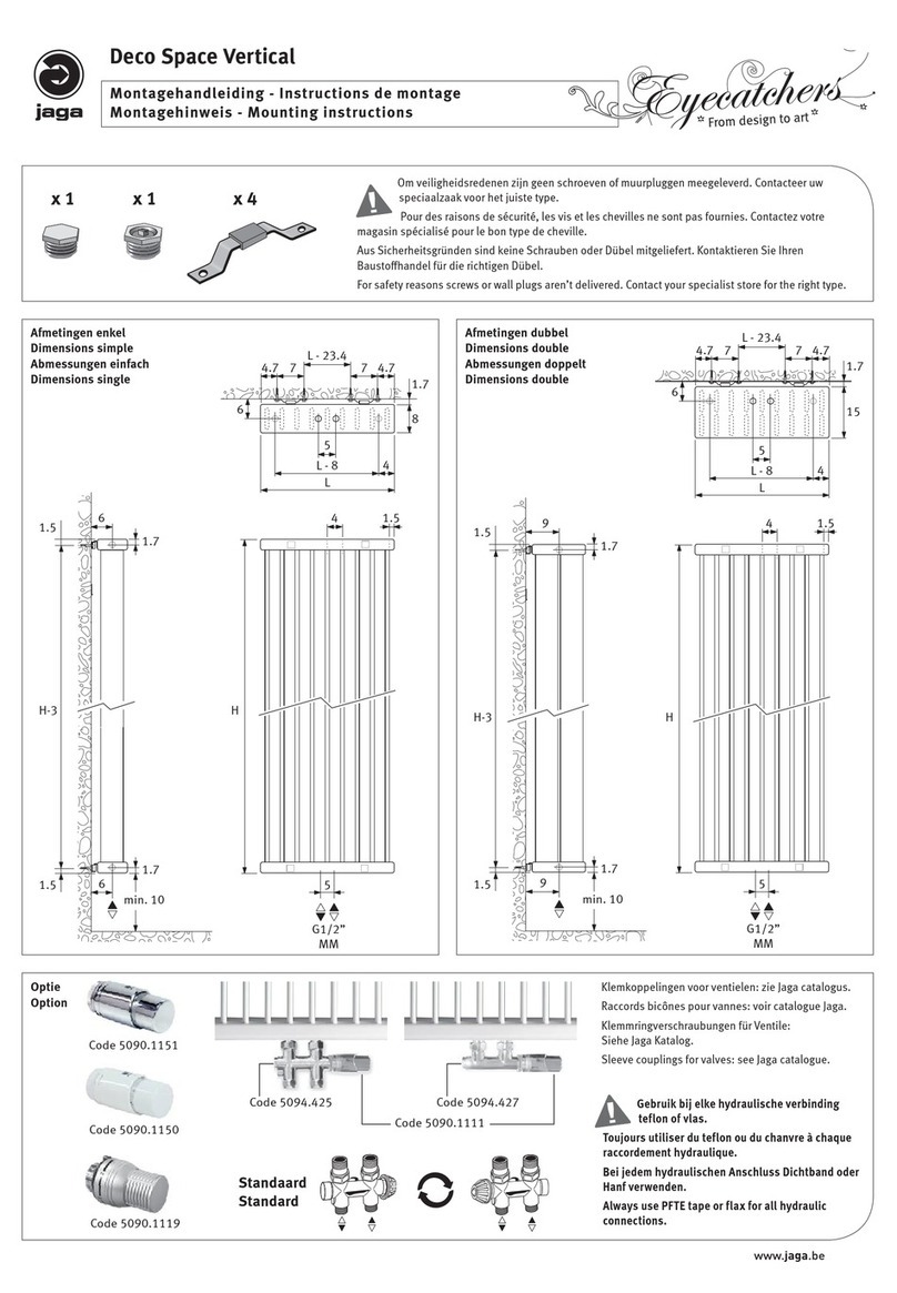
Jaga Eyecatchers  Deco Space Vertical User manual

Jaga

Jaga Eyecatchers Deco Space Vertical User manual

Jaga LINEA PLUS User manual

Jaga

Jaga LINEA PLUS User manual

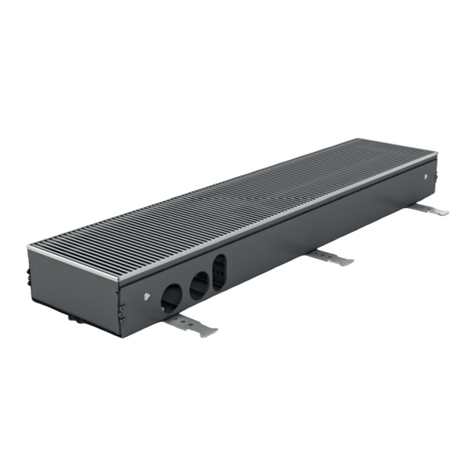
Jaga BRIZA RAD 041 User manual

Jaga

Jaga BRIZA RAD 041 User manual

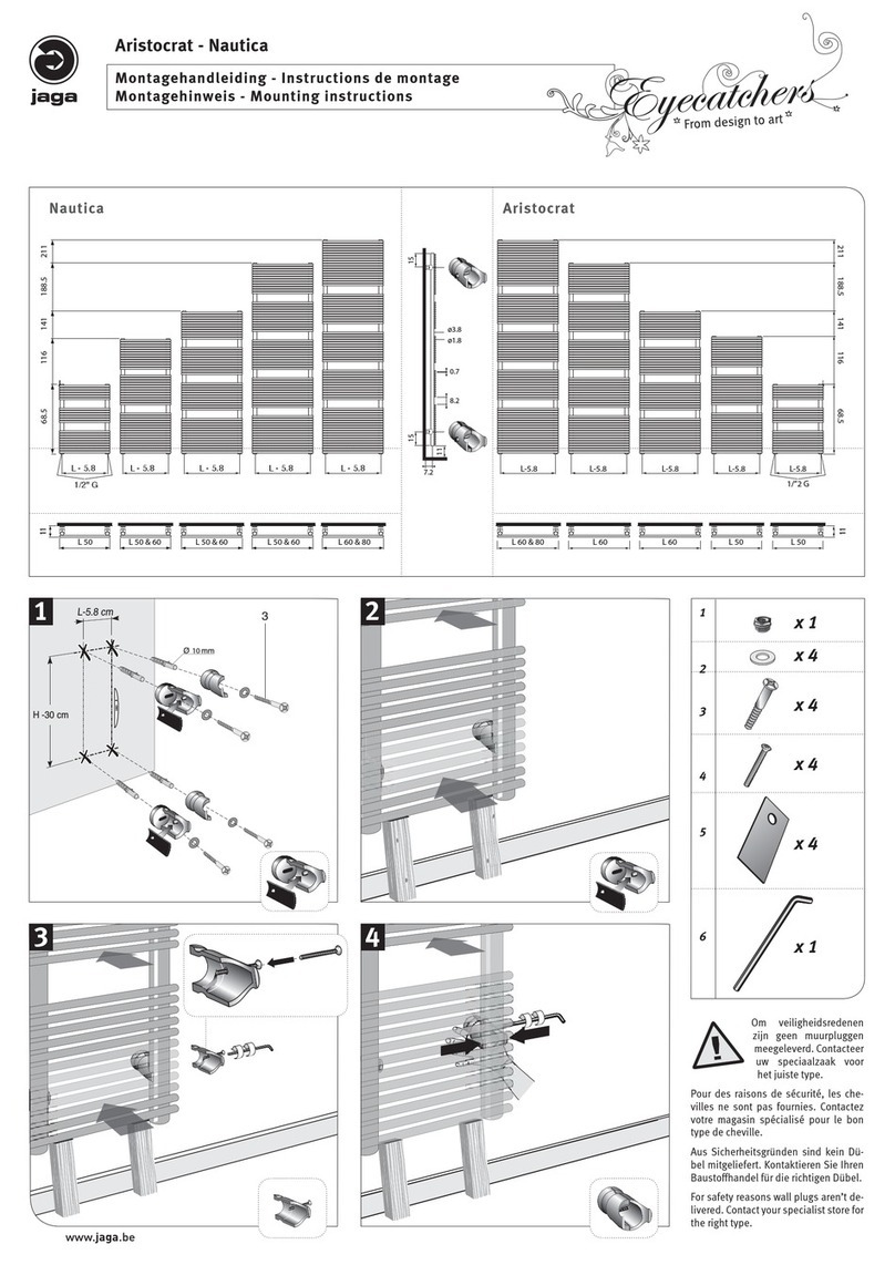
Jaga Aristocrat User manual

Jaga

Jaga Aristocrat User manual

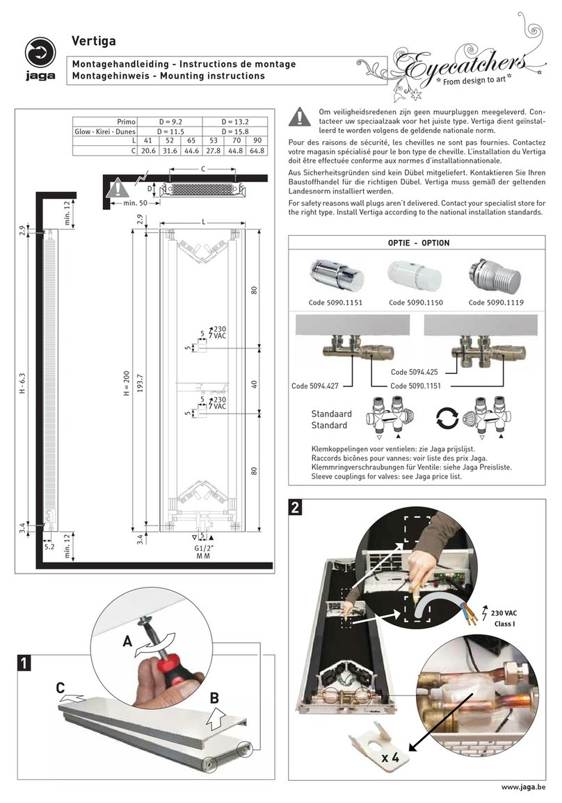
Jaga BRIZA 038/052 User manual

Jaga

Jaga BRIZA 038/052 User manual

Jaga Eyecatchers Iguana Circo User manual

Jaga

Jaga Eyecatchers Iguana Circo User manual

Jaga Eyecatchers Geo 150/50 User manual

Jaga

Jaga Eyecatchers Geo 150/50 User manual

Jaga IGUANA APLANO APLW User manual

Jaga

Jaga IGUANA APLANO APLW User manual

Jaga Helios User manual

Jaga

Jaga Helios User manual

Jaga MINI DYNAMIC CANAL User manual

Jaga

Jaga MINI DYNAMIC CANAL User manual

Jaga Eyecatchers Sani Ronda User manual

Jaga

Jaga Eyecatchers Sani Ronda User manual

Jaga STRADA DBE 2.0 User manual

Jaga

Jaga STRADA DBE 2.0 User manual

Jaga BRIZA 12 User manual

Jaga

Jaga BRIZA 12 User manual

Jaga COCOON User manual

Jaga

Jaga COCOON User manual

Jaga BRIZA 12 PLUG & PLAY User manual

Jaga

Jaga BRIZA 12 PLUG & PLAY User manual

Jaga TEMPO User manual

Jaga

Jaga TEMPO User manual

Jaga Knockonwood DBE KNUF User manual

Jaga

Jaga Knockonwood DBE KNUF User manual

Jaga Maxi WT 2020 User manual

Jaga

Jaga Maxi WT 2020 User manual

Jaga STRADA User manual

Jaga

Jaga STRADA User manual

Popular Heater manuals by other brands

HeatStar HSVFRD20NGBTS Operating instructions and owner's manual

HeatStar

HeatStar HSVFRD20NGBTS Operating instructions and owner's manual

Honeywell HZ-340E User instructions

Honeywell

Honeywell HZ-340E User instructions

Flagro FVP-750 Operating instructions manual

Flagro

Flagro FVP-750 Operating instructions manual

Viessmann VITOLADENS 300-T installation instructions

Viessmann

Viessmann VITOLADENS 300-T installation instructions

Mirrorstone MS-ZEN-12J manual

Mirrorstone

Mirrorstone MS-ZEN-12J manual

Dimplex DHCHT20M instruction manual

Dimplex

Dimplex DHCHT20M instruction manual

Harvia HSWS6U1B Owner's/operator's manual

Harvia

Harvia HSWS6U1B Owner's/operator's manual

EQUATION YD02-5 Assembly, Use, Maintenance Manual

EQUATION

EQUATION YD02-5 Assembly, Use, Maintenance Manual

Vasner 2016650MR Installation guide and user's manual

Vasner

Vasner 2016650MR Installation guide and user's manual

BGS technic 2170 instruction manual

BGS technic

BGS technic 2170 instruction manual

HeatStar HS115TC Operating instructions and owner's manual

HeatStar

HeatStar HS115TC Operating instructions and owner's manual

Eldom HC100 Operating	 instruction

Eldom

Eldom HC100 Operating instruction

Claudgen CH06CSiRX Installation and operating manual

Claudgen

Claudgen CH06CSiRX Installation and operating manual

Ebasto Thermo Top TTC operating instructions

Ebasto

Ebasto Thermo Top TTC operating instructions

Lochinvar 402 Communication instruction manual

Lochinvar

Lochinvar 402 Communication instruction manual

Adler Europe AD 7727 user manual

Adler Europe

Adler Europe AD 7727 user manual

BIEMMEDUE SP 110 instruction manual

BIEMMEDUE

BIEMMEDUE SP 110 instruction manual

cecotec READYWARM 2000 POWER TOWER instruction manual

cecotec

cecotec READYWARM 2000 POWER TOWER instruction manual

manuals.online logo
manuals.online logoBrands
  • About & Mission
  • Contact us
  • Privacy Policy
  • Terms and Conditions

Copyright 2025 Manuals.Online. All Rights Reserved.