V1.00/EN/00477047
Page 2/12Data Sheet 202565
JUMO GmbH & Co. KG
Delivery address: Mackenrodtstraße 14
36039 Fulda, Germany
Postal address:
36035 Fulda, Germany
Phone: +49 661 6003-0
Fax: +49 661 6003-607
Internet: www.jumo.net
JUMO Instrument Co. Ltd.
JUMO House
Temple Bank, Riverway
Harlow, Essex CM20 2DY, UK
Phone: +44 1279 635533
Fax: +44 1279 635262
Internet: www.jumo.co.uk
JUMO Process Control, Inc.
6733 Myers Road
East Syracuse, NY 13057, USA
Phone: 315-437-5866
1-800-554-5866
Fax: 315-437-5860
Internet: www.jumousa.com
Operation
For easy programming and operation, all
parameters are arranged in clearly structured
levels and shown in plain text. Operation is
protected by a code word. This facilitates
individual adaptation of the operation, since
parameters can be generally enabled or
specifically assigned to the protected area.
As an alternative to configuration from the
keys, the instrument can also be configured
through the convenient setup program for PC
(option).
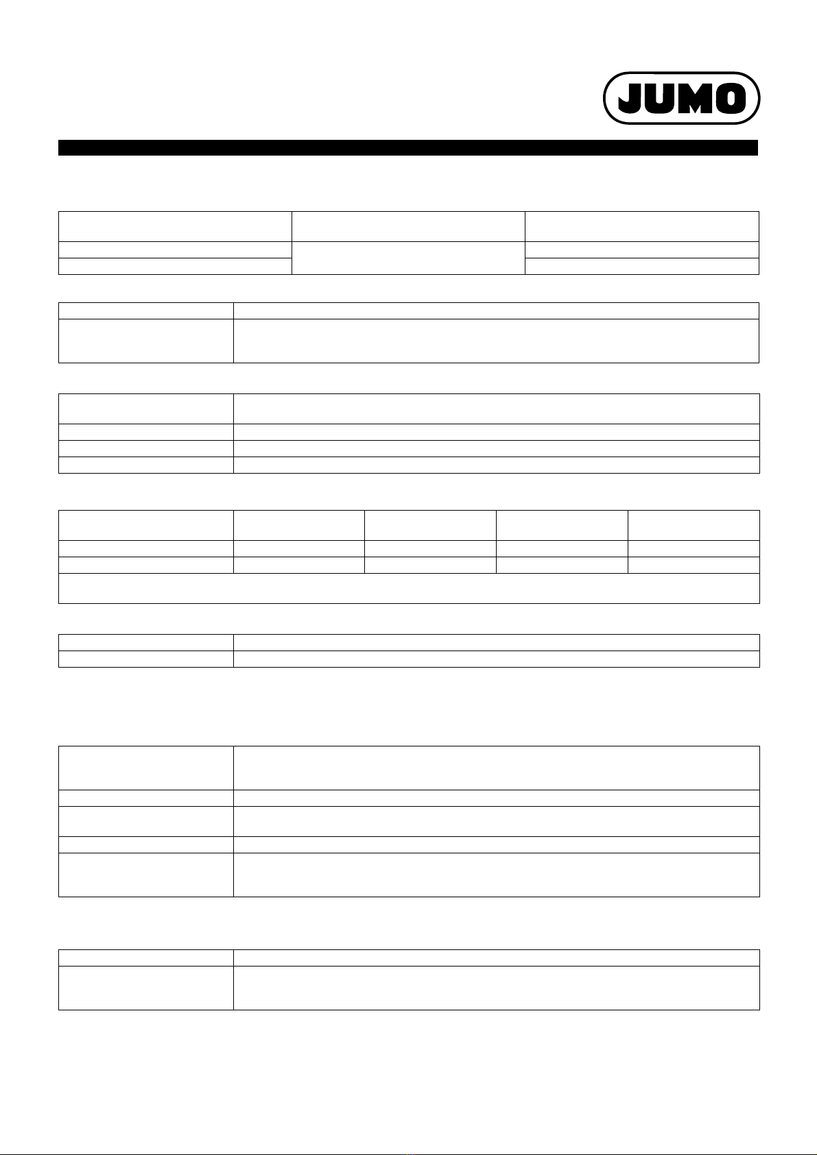
Display modes
Three display modes are available:
Large numbers
In this display mode, the measurements are
shown in digits, as usual.
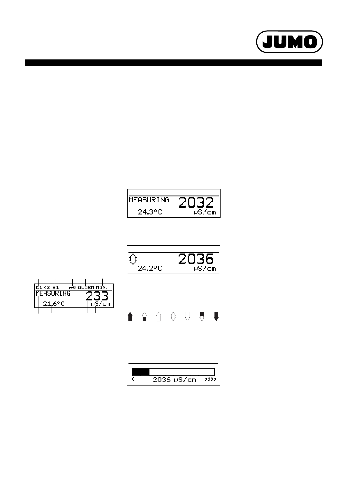
Trend display
The numerical value is supplemented by a
symbol which indicates the change direction
and change speed of the measurement.
This can, for instance, be very useful during
controller optimization.
from left to right:
fast, medium and slow rise, stable,
slow, medium and fast fall.
Bar graph
This display mode allows the user to see at a
glance in which region the measurement is at
present.
The bar graph can be freely scaled.
Function modes
Electrolytic conductivity
Display/control, unit µS/cm or mS/cm.
Resistivity (high-purity water)
Display/control, unit kΩx cm or MΩx cm.
Functional description
The instrument is designed for use on site. A
rugged housing protects the electronics and
the electrical connections from corrosive
environmental conditions (IP67). As an
alternative, the instrument can also be
installed in a control panel, and is then
protected to IP65 on the front. The electrical
connection is made by easy-to-fit pluggable
screw terminals.
Transmitter
Two-electrode cells (standard) as well as four-
electrode cells can be used for measurement.
Two-electrode cells can be connected, in the
usual increments for cell constants (K=0.01;
0.1; 1.0; 3.0 and 10.0). Thanks to the widely
adjustable relative cell constant, it is also
possible to connect sensors with different cell
constants (e.g. K=0.2).
In the case of the 4-electrode cells, the values
K=0.5 and 1.0 have been predefined for the
cell constant. Here too, the instrument can be
matched to sensors with different cell
constants (e.g. K=0.4).
The instrument can perform automatic
temperature compensation, by acquiring the
temperature of the sample solution.
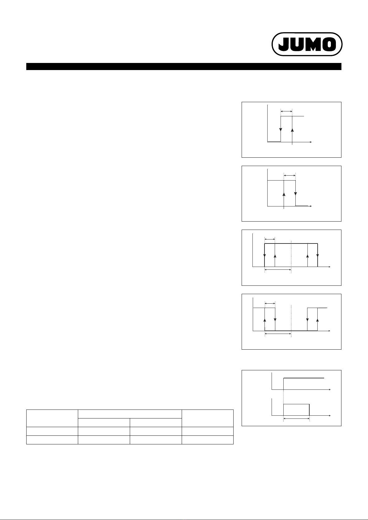
Displays and controls
(1) Switching output 1 or 2 is active
(2) Binary input 1 is actuated
(3) Keypad is inhibited
(4) Alarm has been activated
(5) Instrument is in manual mode
(6) Instrument status
(7) Temperature of medium
(8) Principal measurement
(9) Unit of principal measurement
The user can define what is to be shown in
positions (7) and (8) of the display:
•nodisplay
• compensated or uncompensated
measurement
•temperature
• output level 1 or 2
•setpoint1or2
(1) (2) (4) (5)
(6) (7) (8) (9)
(3)
TDS
Display/control with ppm for the unit.
In this mode, the specific TDS factor can be
entered in addition.
Customer-specific table
In this mode, the input value (conductivity or
resistivity) can be displayed in accordance
with a table (up to 20 value pairs). Thanks to
this function, it is possible to implement
simple concentration measurements, for
example. The values in the table can only be
entered through the optional setup program.
Calibration
Cell constant
Because of manufacturing tolerances, the cell
constant of a conductivity cell may deviate
slightly from its nominal value. In addition, the
cell constant may change during operation
(due to deposits or wear, for example). This
results in a change of the output signal from
the cell. The instrument provides the user with
the possibility of compensating any deviation
from the nominal value of the cell constant by
manual entry or automatic calibration of the
relative cell constant. A manual entry is used,
for instance, for calibration during high-purity
water measurement.
Temperature coefficient
The conductivity of almost all solutions
depends on the temperature. To ensure
correct measurement, it is therefore
necessary to know both the temperature and
the temperature coefficient [%/°C] of the
sample solution. The temperature can either
be measured automatically, with a Pt100 or
Pt1000 temperature probe, or it has to be set
manually by the user.
The temperature coefficient can be
automatically determined by the instrument,
or it can be entered manually.
Calibration logbook
The five most recent successful calibrations
can be called up in the calibration logbook.
This makes it possible to evaluate the ageing
of the sensor that is connected.
Calibration timer
The calibration timer indicates (if required)
when the next routine calibration is due. The
calibration timer is activated by entering a
number of days, after which recalibration has
to be carried out (plant or operator
requirement).
MIN / MAX value memory
This memory acquires the minimum or
maximum input variables that have occurred.
This information serves, for example, to
decide whether the sensor that is connected
is suited to the values that are actually
present.