K&K M3500N User manual

NL
MONTAGEHANDLEIDING
Wij adviseren om de inbouw door een vakwerkplaats te laten uitvoeren.
Neem bij technische vragen contact met ons op via
support@kuk-martendefence.com
VEILIGHEIDSAANWIJZINGEN
• LET OP, HOOGSPANNING!
Hoogspanning is voor gezonde personen weliswaar ongevaarlijk, maar desondanks moet u het contact met de contactplaten vermijden. Dat geldt met name voor
personen met een hartkwaal of pacemaker.
• LET OP, OVERSPANNINGSBESCHERMING!
Zekering bij startassistentie, laswerkzaamheden en snelladen wegnemen.
• Bij werkzaamheden aan elektrische en hybride voertuigen gelden speciale veiligheidsvoorschriften. Neem hiervoor het voertuigspecifieke logboek in acht!
• Het volledige functioneren van het apparaat kan alleen bij voertuigen met een 12 V-accu worden gewaarborgd.
• De aansluiting van een 24V-accu is mogelijk als een spanningsomvormer wordt gebruikt.
• Marterverjager altijd beschermen tegen overmatige hitte en verontreinigingen van de contactplaten voorkomen resp. verwijderen.
• Werkstappen van deze montagehandleiding en de veiligheidsaanwijzingen beslist in acht nemen.
• Wij zijn niet aansprakelijk voor schade die wordt veroorzaakt door het niet in acht nemen van de montagehandleiding.
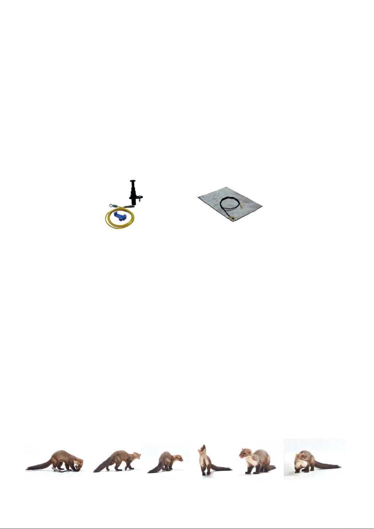
• Maak de motorruimte en parkeerplek voor montage grondig schoon, om territoriumstrijd te voorkomen
(voor de motorruimte adviseren wij de K&K geurvlagverwijderaar, artikel 000300) (8).
Reglementair gebruik:
Het apparaat is bedoeld voor het verjagen van marters en andere wilde dieren uit de motorruimte van personenauto‘s door elektrische schok en agressieve, pulserende
ultrasone frequenties. Nadat de marter een kortsluiting heeft veroorzaakt, wordt de hoogspanningsfunctie tijdelijk uitgeschakeld, om het dier te laten vluchten.
CONTROLE VAN DE WERKING
voor het inbouwen
Alle apparaten worden meerdere keren zorgvuldig door ons gecontroleerd.Voer daarnaast de volgende afsluitende controle uit:
1) Zekering
(1)
wegnemen
(A)
2) Apparaat op plus- en minpool/massa van de auto-accu/carrosserie aansluiten
(E)
3) Zekering plaatsen
(F)
4) Contactplaat
(3)
nu niet meer aanraken
5) Led
(5)
geeft de werking door knipperen aan, dit kan enkele minuten duren.
(H)
6) Hoogspanning kan aanvullend met digitale multimeter op de contactplaat worden gemeten
7) zekering wegnemen
(A)
(LET OP! op de contactplaat staat na wegnemen nog ca. 3 minuten reststroom)
8) Einde controle van de werking
Info:
Garantie uitsluitend op het apparaat, kosten voor montage en demontage worden niet vergoed!
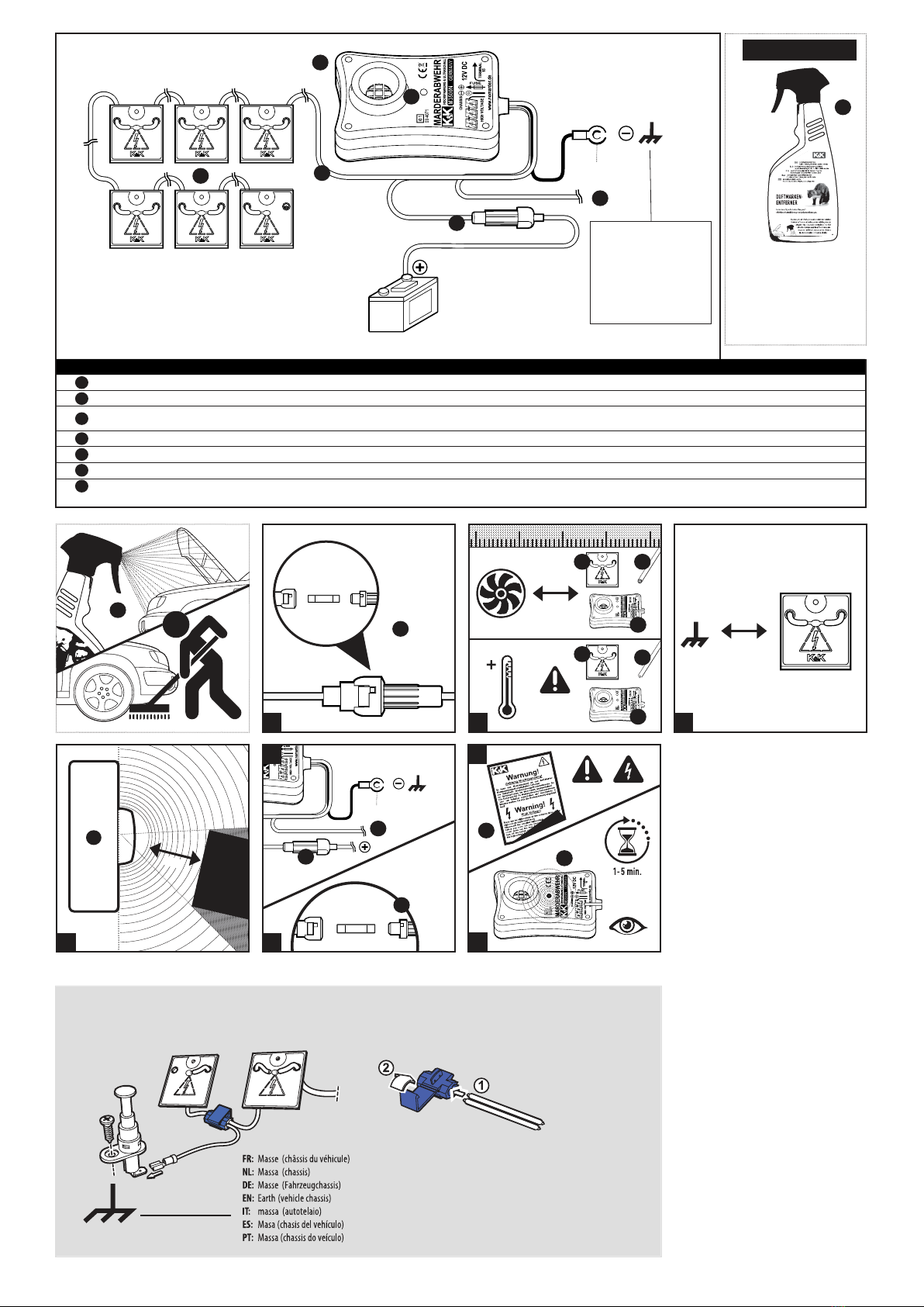
INBOUW
Bij weggenomen zekering
BESTURINGSAPPARAAT
Monteer het basisapparaat
(2)
op een plek, waar dit niet oververhit kan raken (bijv. niet direct bij het spruitstuk)
(B)
en het ultrasone geluid zoveel mogelijk vrij kan uitstralen, om geluidsbelemme-
ring te voorkomen
(D)
. De zekeringhouder
(1)
moet goed bereikbaar worden gemonteerd.
Aansluiting pluskabel met zekeringhouder op pluspool van de 12 V-accu of vergelijkbare plus
(E)
.
Aansluiting massakabel op minpool van de 12V-accu of voertuigmassa
(E)
.
Aansluiting van de kabel‚Klem 15‘
(6)
op klem 15 van het elektrische systeem of een ander contact, dat bij parkerend voertuig op min en bij draaiende motor op plus is geschakeld
(E)
. Als de
kabel wordt aangesloten, wordt de installatie bij draaiende motor uit- en weer ingeschakeld zodra de motor is uitgeschakeld. Als de kabel niet wordt aangesloten, is de installatie in
continubedrijf.
CONTACTPLATEN
Plaats de contactplaten op strategisch beetgevaarlijke plekken in de motorruimte en bevestig deze met kabelbinders. De hoogspanningskabel moet niet direct langs hete en draaiende
motordelen worden gelegd
(B)
. Contactplaten moeten met minimaal 10 mm afstand tot andere geleidende delen en tegen water beschermd worden gemonteerd (gevaar voor kortsluiting)
(C)
.
De contactplaten moeten zo worden geïnstalleerd, dat de marter tegelijkertijd ook een ander geleidend deel kan aanraken, om een schok te veroorzaken.Ter ondersteuning kan een massamat
worden gebruikt (artikel 1003).
Breng de gele waarschuwingssticker‚Let op, hoogspanning‘ (7) goed zichtbaar in de motorruimte aan (G)!
INBEDRIJFNAME
Plaats de zekering weer terug
(F)
. Als het apparaat correct is aangesloten, begint de controle-led
(5)
op het basisapparaat te knipperen (iedere 3 – 12 seconden). Bij de eerste inbedrijfname kan
deze procedure enkele minuten duren
(H)
. In deze toestand mogen de contactplaten niet worden aangeraakt.
De M3500N is een eectieve en uitgebreide marterverjager. Deze combineert ultrasoon geluid en hoogspanning om marters zo goed mogelijk te verjagen. Desondanks kunnen wij niet
garanderen dat de marter in 100% van de gevallen wordt verjaagd.
VERDERE AANWIJZINGEN
Als het apparaat niet werkt, kan dat de volgende oorzaken hebben:
1) Bedrijfsspanning ligt niet tussen 11,5 V en 15V.
2) De leiding naar klem 15 is niet correct aangesloten
(E)
.
3) De contactplaten raken andere geleidende delen aan (kortsluiting)
(C)
.
4) Zekering zit niet in de zekeringhouder of is defect
(1)
.
5) Inschakelen pas na enkele seconden vertraging. U moet eventjes geduld hebben
(H)
.
Verwijdering:
Het apparaat mag niet met het huishoudelijk afval worden verwijderd.
Informeer bij uw gemeente over correcte verwijdering.
Accessoires
- Motorkapschakelaar met directe ontlading No 1001
- Massamat No 1003
TECHNISCHE GEGEVENS
• Bedrijfsspanning: 12V auto-accu
• Gemiddeld stroomverbruik: < 5 mA
• Accubewaker: automatische uitschakeling
bij een accuspanning < 11,5V (± 5%)
• Ultrasone frequentie: ca. 22 kHz (± 10%)
• Geluidsniveau: ca. 100 dB (± 15%)
• Stralingshoek: ca. 150°
• Luidspreker: speciale keramische piëzo-luidspreker
met aluminium tweetermembraan
• Uitgangsspanning: ca. 200 tot 300V
• Temperatuurbereik: ca. -25°C tot +80°C
• Functie-indicatie: knipperende LED (ca. om de 5 tot 12 sec.)
• Afmetingen regeleenheid: ca. 120 x 80 x 40 mm
• Hoogspannings-contactplaten: 6 stuks, ca. 40 x 40 x 1,5 mm
• Kabellengte hoogspanningskabel: ca. 4 m (± 10%)
• Zekering in zekeringhouder: 500 mA
Goedgekeurd door het Duitse Kraftfahrt-Bundesamt met
het E1-teken.

M3500N
MARDERABWEHRGERÄT
MARTENREPELLENT DEVICE | REPOUSSEMARTRE
02044
Das KOMBI Marderabwehrgerät
Vereint pulsierenden Sinus-Ultraschall mit sechs fix
auf einem Kabelstrang montierten Hochspannungs-
Kontakten.
HOCHSPANNUNG
SINUS ULTRASCHALL
ÄUSSERST GERINGE STROMAUFNAHME
EN FR
CZ
PL
IT
NL
HIGH VOLTAGE
SINE ULTRASOUND
EXTREMELY LOW POWER CONSUMPTION
HAUTE TENSION
ULTRASONS SINUSOÏDAUX
CONSOMMATION DE COURANT EXTRÊMEMENT
FAIBLE
Odpuzovač kun: Agresivní ultrazvuk a vysoké napětí odpuzuje
škodlivé hlodavce z motorového prostoru.
Sistema scaccia martore: grazie agli ultrasuoni intensi e all‘alta
tensione, i roditori vengono allontanati dal vano motore.
Marterverjaging: met agressief ultrageluid en hoogspanning
worden de lastige knaagdieren uit de motorruimte verdreven.
Urządzenie odstraszające kuny: Agresywne ultradźwięki iwysokie
napięcie odstraszają uciążliwe gryzonie od komory silnika.
kuk-marderabwehr.de | martendefence.com | defensemartre.fr
Lieferumfang/scope of delivery/Fournitur:
1 Gerät mit Kabelstrang und 6 Platten/
module with cable and 6 plates/
module avec câblage et 6 contacts
1 allgemeinerWarnaufkleber/general warning sticker/
autocollant avertissement
1 Montageanleitung/installation manual/notice de
montage
Zubehör
- Motorhaubenschalter mit Sofortentladung No 1001
- Massematte No 1003
Accessories
- Bonnet switch for immediate discharge No 1001
- Earthing mat No 1003
Accessoires
- Détecteur d‘ouverture du capot avec déchargement immédiat No 1001
-Tapis de masse No 1003“
Akcesoria
- wyłacznik pokrywy silnika z natychmiastowym rozładowaniem No 1001
- Mata masy No 1003
Příslušenství
- Spínac kapoty motoru s okamžitým vybitím No 1001
- Kostricí rohož No 1003
Accessoires
- Interruttore per cofano motore con scaricamento immediato No 1001
-Tappetino di massa No 1003
Accessori
- Motorkapschakelaar met directe ontlading No 1001
- Massamat No 1003
No. 1003
support@kuk-marderabwehr.de support@martendefence.com support@defensemartre.fr
K&K Handelsgesellschaft mbH, Germany | D-68723 Oftersheim, Gewerbepark Hardtwald 14 | Tel. +49 (0) 6202-85 932 0
No. 1001
3
DE: Masse (Fahrzeugchassis)
EN: Earth (vehicle chassis)
FR: Masse (châssis du véhicule)
PL: ukostîeni (podvozek)
IT: massa (autotelaio)
CZ: Masa (rama pojazdu)
NL: Massa (chassis)
DE EN FR PL IT CZ NL
1x 1
1x
6x 3
4m 4
1x
LED LED LED
7
Steuergerät
Hochspannungs-
Kontaktplatten
Hochspannungskabel
Sicherheitswarnaufkleber
Řídicí jednotka
Vysokonapěťový kabel
LED
Bezpečnostní výstražná
nálepka
LED
Dispositivo di comando
Cavi di alta tensione
Adesivi con avvertenze
di sicurezza
Jednostka sterująca
Kabel wysokiego napięcia
LED
Naklejka z ostrzeżeniem
LED
Besturingsapparaat
Hoogspanningskabel
Veiligheidswaarschuwings-
sticker
Control unit Bloc de commande
High-voltage cable Câble de haute tension
Warning sticker Autocollant d'avertissement
1
max.
2
G
F
D
C
7
min. 10 mm
A
1
0,5 A (1 A)
1
B
2
3
min. 10 cm
max. 85° C
4
2
34
B
H
E
8
5
1
6
1
2
34
5
6
Sicherung
Anschluss Klemme 15
1
2
3
4
5
6
7
Fuse PojistkuProtection ZekeringBezpiecznik Fusibile
Connection terminal 15 Raccordement pince 15 Aansluiting Klem 15Podłączenie zacisk 15 Collegamento morsetto 15 Připojení svorka 15
0,5 A (1 A)
High voltage
contact plates Kontaktními deskami Hoogspannings-
contacten
Styki wysokiego napięcia Piastre di contattoPlaques contact
à haute tension
DE: K&K Duftmarkenentferner
EN:
FR:Destructeur de marques olfactives
PL:
IT:
CZ:
NL:
8
OPTIONAL
Art.-Nr.:
000300
Odstraňovač pachových stop
Prodotto per rimozione tracce
Preparat do usuwania zapachów
Geurvlagverwijderaar
Scent mark remover
Zubehör/ Accessories/ Accessoires
/
Akcesoria/ Příslušenství/Accessoires
/
Accessori
: No.1001

MONTAGEANLEITUNG
Wir empfehlen den Einbau durch eine Fachwerkstatt.
Bei technischen Fragen erreichen Sie uns unter
support@kuk-marderabwehr.de
SICHERHEITSHINWEISE
• ACHTUNG HOCHSPANNUNG!
Die Hochspannung ist für gesunde Menschen zwar ungefährlich, dennoch sollten Sie den Kontakt mit den Kontaktplatten vermeiden. Dies gilt besonders für
Personen mit Herzleiden oder Herzschrittmacher.
• ACHTUNG ÜBERSPANNUNGSSCHUTZ!
Sicherung bei Starthilfe, Schweißarbeiten und Schnellladen entnehmen.
• Bei Arbeiten an Elektro- und Hybridfahrzeugen gelten besondere Sicherheitsbestimmungen. Bitte beachten Sie diesbezüglich das fahrzeugspezifische Bordbuch!
• Die volle Funktionstüchtigkeit des Gerätes kann nur bei Fahrzeugen mit einer 12 V Batterie gewährleistet werden
• Der Anschluss an eine 24V Batterie ist möglich, wenn ein Spannungswandler genutzt wird.
• Marderabwehrgerät stets vor übermäßiger Hitze schützen undVerschmutzungen der Kontaktplatten vermeiden bzw. beseitigen.
• Arbeitsschritte dieser Montageanleitung und deren Sicherheitshinweise unbedingt einhalten.
• Schäden, die durch Nichtbeachten der Montageanleitung verursacht werden, sind von jeglicher Haftung ausgeschlossen.
• Säubern Sie Motorraum und Parkplatz gründlich vor der Montage, um Revierkämpfe zu vermeiden
(wir empfehlen für den Motorraum den K&K Duftmarkenentferner, Artikel 000300) (8).
Bestimmungsgemäße Verwendung:
Das Gerät dient demVertreiben von Mardern und anderenWildtieren aus dem Motorraum von Kraftfahrzeugen durch Elektroschock und aggressive,
pulsierende Ultraschallfrequenzen. Nachdem der Marder einen Kurzschluss ausgelöst hat, schaltet die Hochspannungsfunktion kurzzeitig ab, um demTier eine Fluchtmöglichkeit zu geben.
FUNKTIONSPRÜFUNG
vor Einbau
Alle Geräte werden von uns mehrfach sorgfältig geprüft. Bitte führen Sie darüber hinaus folgende abschließende Prüfung durch:
1) Sicherung
(1)
entnehmen
(A)
2) Gerät an Plus- und Minuspol/Masse der Autobatterie/Karosserie anschließen
(E)
3) Sicherung einsetzen
(F)
4) Kontaktplatte
(3)
jetzt nicht mehr berühren
5) LED
(5)
zeigt durch Blinken die Funktion an, dies kann einige Minuten dauern
(H)
6) Hochspannung kann zusätzlich mit digitalem Multimeter an der Kontaktplatte gemessen werden
7) Sicherung entnehmen
(A)
(ACHTUNG! Kontaktplatte führt nach Entnahme noch ca. 3 Minuten Reststrom)
8) Ende Funktionsprüfung
Info:
Gewährleistung ausschließlich auf das Gerät, keine Übernahme von Montage und Demontagekosten!
EINBAU
bei entnommener Sicherung
STEUERGERÄT
Montieren Sie das Basisgerät
(2)
an einer Stelle, wo es nicht überhitzen kann (z.B. nicht direkt am Auspukrümmer)
(B)
und der Ultraschall möglichst frei strahlen kann, um Schallschatten zu
vermeiden
(D)
. Der Sicherungshalter
(1)
sollte gut erreichbar montiert werden.
Anschluss Pluskabel mit Sicherungshalter an Pluspol der 12V Batterie oder vergleichbares Plus
(E)
.
Anschluss Massekabel an Minuspol der 12V Batterie oder Fahrzeugmasse
(E)
.
Anschluss des Kabels‚Klemme 15‘
(6)
an Klemme 15 des Bordnetzes oder einen anderen Kontakt, der bei parkendem Fahrzeug auf Minus und bei laufendem Motor auf Plus geschaltet ist
(E)
.
Wird das Kabel angeschlossen, schaltet sich die Anlage bei laufendem Motor aus und wieder ein, sobald der Motor aus ist.Wird das Kabel nicht angeschlossen, ist die Anlage im Dauerbetrieb.
KONTAKTPLATTEN
Verlegen Sie die Kontaktplatten strategisch günstig an bissgefährdeten Stellen im Motorraum und befestigen Sie diese mit Kabelbindern. Das Hochspannungskabel sollte nicht direkt an heißen
und drehenden Motorteilen vorbeigeführt werden
(B)
. Kontaktplatten sollten mit mindestens 10 mm Abstand zu anderen leitendenTeilen und wassergeschützt montiert werden (Kurzschlussge-
fahr)
(C)
. Die Kontaktplatten sollten so installiert werden, dass der Marder gleichzeitig auch ein anderes leitendesTeil berühren kann, um einen Schlag auszulösen. Als Unterstützung kann eine
Massematte ergänzt werden (Artikel 1003).
Bitte bringen Sie den gelbenWarnaufkleber‚Achtung Hochspannung‘ (7) gut sichtbar im Motorraum an (G)!
INBETRIEBNAHME
Setzen Sie die Sicherung wieder ein
(F)
.Wenn das Gerät richtig angeschlossen wurde, beginnt die Kontroll-LED
(5)
am Basisgerät zu blinken (ca. alle 3 – 12 Sekunden). Bei der ersten Inbetriebnah-
me kann dieserVorgang einige Minuten dauern
(H)
. In diesem Zustand nicht die Kontaktplatten berühren.
Das M3500N ist eine wirkungsvolle und umfassende Abwehrlösung, es kombiniert Ultraschall und Hochspannung, um eine bestmögliche Abwehrleistung zu erzielen. Trotzdem können wir keine
Garantie dafür übernehmen, dass in 100% aller Fälle der Marder vertrieben wird.
WEITERE HINWEISE
Funktioniert das Gerät nicht, könnte das folgende Ursachen haben:
1) Betriebsspannung liegt nicht zwischen 11,5 V und 15V.
2) Die Leitung zu Klemme 15 ist nicht korrekt angeschlossen
(E)
.
3) Die Kontaktplatten berühren andere leitendeTeile (Kurzschluss)
(C)
.
4) Sicherung ist nicht im Sicherungshalter oder defekt
(1)
.
5) Einschalten läuft mit mehreren SekundenVerzögerung ab. Haben Sie etwas Geduld
(H)
!
Entsorgung:
Das Gerät darf nicht im Hausmüll entsorgt werden.
Erkundigen Sie sich bei Ihren lokalen Behörden über die ordnungsgemäße Entsorgung.
Zubehör
- Motorhaubenschalter mit Sofortentladung No 1001
- Massematte No 1003
TECHNISCHE DATEN
• Betriebsspannung: 12V Autobatterie
• Stromaufnahme durchschnittlich: < 5 mA
• Batteriewächter: Abschaltautomatik
bei Batteriespannung < 11,5V (± 5%).
• Ultraschallfrequenz: ca.22 kHz (± 10%)
• Schalldruck: ca. 110 dB ( ±15%)
• Abstrahlwinkel Ultraschall: ca. 150°
• Lautsprecher: Keramik-Spezial-Piezolautsprecher
mit Alu-Kalottenmembran
• Ausgangsspannung: ca. 200 - 300V
• Temperaturbereich: ca. -25...+80°C
• Funktionsanzeige: blinkende LED (ca. alle 5 - 12 Sek.)
• Maße Steuergerät: ca. 120 x 80 x 40 mm
• Hochspannungskontaktplatten: 6 Stück, je ca. 40 x 40 x 1,5 mm
• Kabellänge Hochspannungskabel: ca. 4 m (± 10%)
• Sicherung im Sicherungshalter: 500 mA
Zulassung durch das Kraftfahrt-Bundesamt mit dem E1
Zeichen.
DE

POKYNY K INSTALACI
Doporučujeme, aby montáž provedl autoservis.
V případě technických dotazů nás můžete kontaktovat na adrese
support@kuk-martendefence.com
BEZPEČNOSTNÍ UPOZORNĚNÍ
• POZOR, VYSOKÉ NAPETÍ!
Ackoli není toto vysoké napetí pro zdravého cloveka nebezpecné, presto by se lidé meli vyhýbat kontaktu s kontaktními deskami. Platí to zejména pro osoby s
nemocemi srdce a kardiostimulátorem.
• POZOR, OCHRANA PŘED PŘEPĚTÍM!
V případě provádění pomoci při startu, svařovacích prací a rychlého nabíjení. Při práci na elektrických a hybridních vozidlech platí zvláštní bezpečnostní
předpisy. V tomto ohledu prosím respektujte provozní knihu konkrétního vozidla!
• Plnou funkčnost přístroje lze garantovat jenom u vozidel s baterií 12V.
• Připojení k baterii 24V je možné, pokud se použije měnič napětí.
• Odpuzovac kun vždy chrante pred nadmerným horkem a zamezte znecištení kontaktních desek, resp. jej odstrante.
• Je nutné bezpodmínečně dodržet pracovní kroky popsané v tomto návodu k montáži a také bezpečnostní upozornění.
• Na škody způsobené nedodržením návodu k montáži se ručení nevztahuje.
• Před montáží důkladně vyčistěte prostor motoru i parkovací plochu, abyste zamezili soubojům o revír
(pro prostor motoru doporučujeme odstraňovač pachových stop K&K, položka 000300) (8).
Použití v souladu s určením:
Prístroj slouží k odpuzovaní kun a jiných divokých zvírat z prostoru motoru motorových vozidel formou elektrošoku a agresivních pulzujících ultrazvukových
frekvencí. Jakmile kuna vyvolá zkrat, vypne se na krátký cas funkce vysokého napetí, aby melo zvíre možnost prchnout.
ZKOUŠKA FUNKCNOSTI
pred zabudováním
Všechny prístroje opakovane peclive proverujeme. Presto vás prosíme, abyste provedli ješte záverecnou kontrolu:
1)Vyjmete
(A)
pojistku
(1)
2) Prístroj spojte s plusovým a mínusovým pólem / uzemnením autobaterie / karoserie
(E)
3) Nasadte pojistku
(F)
4) Kontaktní desky
(3)
se ted už nedotýkejte
5) LED
(5)
blikáním indikuje funkci, což ovšem muže nekolik minut trvat.
(H)
6)Vysoké napetí mužete na kontaktní desce dodatecne zmerit digitálním multimetrem
7) vyjmete pojistku
(A)
(POZOR! Kontaktní deska vede i po vyjmutí ješte zhruba 3 minuty zbytkový elektrický proud)
8) Konec zkoušky funkcnosti
Info:
Záruka se týká pouze přístroje, nepřebíráme náklady na montáž a demontáž!
ZABUDOVÁNÍ
za predpokladu vyjmuté pojistky
RÍDICÍ PRÍSTROJ
Základní prístroj
(2)
namontujte na takové místo, kde nemuže dojít k jeho prehrátí (napr. ne prímo na koleni výfuku)
(B)
a kde muže pokud možno volne vyzarovat ultrazvuk, aniž aby došlo ke
vzniku míst ve stínu ultrazvuku
(D)
. Držák pojistky
(1)
byste meli namontovat tak, aby byl dobre prístupný.
Pripojení plusového kabelu s držákem pojistky k plusovému pólu baterie 12V nebo srovnatelnému plusu
(E)
.
Pripojení zemnícího kabelu k mínusovému pólu baterie 12V nebo ke kostre vozidla
(E)
.
Pripojení kabelu‚svorka 15‘
(6)
ke svorce 15 palubní síte nebo k jinému kontaktu, který je u parkujícího vozidla zapojený k mínusu a u jedoucího motoru k plusu
(E)
. Po pripojení kabelu se zarízení
v prípade motoru v provozu vypne a zapne se, jakmile se vypne motor. Pokud tento kabel nepripojíte, bude zarízení v trvalém provozu.
KONTAKTNI DESKY
Kontaktní desky položte strategicky výhodne na taková místa v prostoru motoru, která jsou ohrožená prokousnutím, a pripevnete je pomocí stahovacích pásku. Vysokonapetový kabel byste nemeli
vést prímo kolem horkých a rotujících cástí motoru
(B)
. Kontaktní desky byste meli namontovat ve vzdálenosti nejméne 10 mm od jiných vodivých dílu a tak, aby byly chráneny pred vodou (nebezpe-
cí zkratu)
(C)
. Kontaktní desky byste meli instalovat tak, aby se kuna soucasne dotkla také jiného vodivého dílu, aby vyvolala úder. Jako podporu si mužete zakoupit zemnící rohož (položka 1003).
Žlutou výstražnou nálepku‚Pozor, vysoké napetí‘ (7) nalepte v prostoru motoru dobre viditelne (G)!
UVEDENÍ DO PROVOZU
Pojistku opet nasadte
(F)
. Když je prístroj správne zapojen, zacne na základním prístroji blikat kontrolní LED
(5)
(cca po 3–12 vterinách).V prípade prvního uvedení do provozu muže tento proces
trvat nekolik minut
(H)
.V tomto stavu se kontaktních desek nedotýkejte.
M3500N predstavuje úcinné a komplexní rešení odpuzování, které kombinuje ultrazvuk a vysoké napetí za úcelem dosažení nejlepšího možného efektu odpuzování.
Presto nemužeme na 100% zarucit, že kuna bude pokaždé odpuzena.
DALŠÍ UPOZORNENÍ
Pokud prístroj nefunguje, muže to mít následující príciny:
1) Provozní napetí není v rozsahu 11,5V až 15 V.
2)Vedení ke svorce 15 není správne pripojené
(E)
.
3) Kontaktní desky se dotýkají jiných vodivých dílu (zkrat)
(C)
.
4) Pojistka není v držáku pojistky nebo je defektní
(1)
.
5) Zapnutí nastane se skluzem nekolika vterin. Mejte strpení
(H)
!
Likvidace:
Prístroj se nesmí likvidovat jako smesný odpad z domácností.
Zeptejte se místních úradu, jakým zpusobem prístroj zlikvidujete tak, aby to odpovídalo právním predpisum.
Príslušenství
- Spínac kapoty motoru s okamžitým vybitím No 1001
- Kostricí rohož No 1003
TECHNICKÉ ÚDAJE
• Provozní napětí: Autobaterie 12 V
• Příkon průměrně: < 5 mA
• Sledování baterie: odpojovací automatika,
pri napetí baterie < 11,5V (± 5%)
• Frekvence ultrazvuku: cca 22 kHz (± 10 %)
• Akustický tlak: cca 100 dB (± 15%)
• Úhel vyzařování: cca 150 °
• Reproduktor: Speciální piezokeramický
reproduktor s alukalotovou membránou
• Výstupní napetí: cca 200 - 300V
• Teplotní rozsah: cca -25 °C až +80 °C
• Ukazatelchodu: blikající LEDdioda (cca každých 5 -12 sekund)
• Rozmery rídicí jednotky:cca 120 x80 x 40 mm
• Vysokonapetovékontaktnídesticky:6 kusu, pocca 40 x40 x 1,5mm
• Délka vysokonapetového kabelu: cca4 m (±10%)
• Pojistkavpojistkovémdržáku:500 mA
Schválení Spolkovým úřadem pro dopravu se značkou E1.
CZ

INSTALLATION INSTRUCTIONS
We recommend installation by a specialist workshop.
If you have any technical questions, please contact us at
support@kuk-martendefence.com
SAFETY INFORMATION
• WARNING: HIGH-VOLTAGE!
High voltage is not harmful to healthy persons.You should, however, avoid contact with the contact plates.This applies in particular to people with heart disease
or heart pacemakers.
• WARNING: OVERVOLTAGE PROTECTION!
Remove the fuse when jump starting, carrying out welding work and for rapid charge.There are particular safety regulations applicable when
working on electric and hybrid vehicles. Please observe the logbook for the vehicle with regards to this.
• We can only guarantee the full functioning of the device for vehicles with a 12V battery.
• Connection to a 24V battery is possible if you use a voltage transformer.
• Always protect the marten repellent device against excessive heat and prevent or eliminate dirt on the contact plates.
• Always comply with the working steps in these installation instructions and the safety information.
• Damage caused by not observing the installation instructions is excluded from any liability.
• Clean the engine compartment and parking space thoroughly before installation in order to avoid turf wars
(we recommend the K&K scent mark remover for the engine compartment, item 000300) (8).
Intended use:
The device is used to expel martens and other wild animals from the vehicle engine compartment by means of electric shock and aggressive, pulsating ultrasound frequencies.
After the marten has triggered a short circuit, the high-voltage function is switched o for a short time in order to give the animal the opportunity to escape.
FUNCTION TEST
prior to installation
All devices are carefully checked by us multiple times. Please also carry out the following nal checks:
1) Remove
(A)
the fuse
(1)
2) Connect the device to the positive and negative pole/earth of the car battery/vehicle body
(E)
3) Insert fuse
(F)
4) Don’t touch the contact plate
(3)
any more
5) LED
(5)
ashes to indicate it is working.This can take a few minutes.
(H)
6) High voltage can also be measured using a digital multimeter on the contact plate
7) Remove the fuse
(A)
(WARNING! After removal, contact plate will carry approx. 3 minutes of residual current)
8) End of function test
Info:
Warranty is exclusively for the device.There is no assumption of assembly and disassembly costs!
INSTALLATION
when fuse has been removed
CONTROL UNIT
Mount the basic device
(2)
in a place where it cannot overheat (e.g. not directly on the exhaust manifold)
(B)
and the ultrasound can radiate as freely as possible in order to avoid
acoustic shadow
(D)
.The fuse holder
(1)
should be mounted so it is easily accessible.
Connection of the positive cable with fuse holder to the positive pole of the 12V battery or comparable positive terminal
(E)
.
Connection of earth cable to minus pole of the 12V battery or vehicle earth
(E)
.
Connection of the vehicle terminal 15 cable
(6)
to wiring system’s vehicle terminal 15 or another contact, which is switched to negative for parked vehicles and positive for running engines
(E)
.
If the cable is connected, the system switches o when the engine is running and switches back on again once the engine is turned o. If the cable is not connected, the system is in continuous
operation.
CONTACT PLATES
Lay the contact plates strategically in bite-endangered areas in the engine compartment and secure them with cable ties.The high-voltage cable should not be placed anywhere near hot and/or
rotating engine parts
(B)
. Contact plates should be mounted at a minimum distance of 10mm to other conductive parts and in such a way as to ensure they are protected from water (short-circuit
hazard)
(C)
.The contact plates should be installed so that the martens can simultaneously touch another conductive part to trigger an electric shock. An earthing mat can be added as support
(item 1003).
Please attach the yellow warning sticker‘Warning high voltage’(7) so it can be clearly seen in the engine compartment (G)!
INITIAL OPERATION
Re-insert the fuse
(F)
. If the device has been correctly connected, the control LED
(5)
on the basic device will start to ash (approx. every 3-12 seconds).This procedure may take a few minutes
when operating for the rst time
(H)
. In this state, do not touch the contact plates.
The M3500N is an eective and comprehensive defence solution. It combines ultrasound and high voltage in order to achieve the best possible defensive performance. Despite this, we cannot
guarantee that the martens will be expelled in 100% of all cases.
MORE INFORMATION
If the device does not work, it could be for the following reasons:
1) Operating voltage is not between 1,5V and 15V.
2)The cable to vehicle terminal 15 has not been connected correctly
(E)
.
3)The contact plates are touching other conductive parts (short circuit)
(C)
.
4) Fuse is not in the fuse holder or is faulty
(1)
.
5)There is a delay of several seconds when switching on. Have patience
(H)
!
Disposal:
The device may not be disposed of in household waste.
Please contact your local authority for the correct disposal method.
Accessories
- Bonnet switch for immediate discharge No 1001
- Earthing mat No 1003
TECHNICAL DATA
• Operating voltage: 12V car battery
• Average power consumption: < 5 mA
• Battery monitor: switches o automatically
when battery voltage < 11,5V (±5%)
• Ultrasound frequency: approx. 22 kHZ (± 10%)
• Sound pressure: approx. 100 dB (± 15%)
• Radiation angle: approx. 150°
• Loudspeaker: ceramic special Piezo loudspeaker
with aluminium dome-shaped diaphragm
• Output voltage: approx. 200 - 300 V
• Operating temperature range: approx. -25C to +80°C
• Function display: lashing LED (approx. every 5 - 12 sec.)
• Dimensions of control device: approx. 120 x 80 x 40 mm
• High-voltage contact plates: 6 x, each approx. 40 x 40 x 1.5 mm
• Cable length of high voltage cable: approx. 4 m (± 10%)
• Fuse in fuse holder: 500 mA
Approved by the Kraftfahrt-Bundesamt (Federal Motor
Transport Authority) with the E1 symbol.
EN

FR
INSTRUCTIONS DE MONTAGE
Nous recommandons un montage par un atelier spécialisé.
En cas de questions d‘ordre technique, contactez-nous via
support@kuk-defensemartre.fr
CONSIGNES DE SÉCURITÉ
• ATTENTION, HAUTETENSION!
La haute tension n‘est certes pas dangereuse pour les personnes en bonne santé, mais il convient tout de même d‘éviter le contact avec les plaques de contact.
Cela s‘applique notamment aux personnes avec des problèmes cardiaques ou un stimulateur cardiaque.
• ATTENTION, PROTECTION CONTRE LA SURTENSION!
Retirez la protection pour l‘aide au démarrage, les travaux de soudure et le chargement rapide.
• Les consignes de sécurité sont particulièrement importantes lors de travaux sur des véhicules électriques et hybrides.Veuillez consulter le livre de bord du véhicule à ce propos!
• Un bon fonctionnement de l`appareil peut seulement être garanti pour les vehicules avec une batterie de 12V.
• Le raccordement à une batterie 24 V est possible en cas d`utilisation d`un convertisseur de tension.
• Protégez toujours l‘appareil repousse-martres contre une chaleur trop élevée et évitez ou nettoyez l‘encrassement des plaques de contact.
• Les étapes de travail des présentes instructions de montage doivent impérativement être respectées.
• Les dommages entraînés par un non-respect des instructions de montage sont exclus de toute responsabilité.
• Nettoyez soigneusement le compartiment moteur et la place de stationnement avant le montage, pour éviter les combats de défense du territoire
(pour le compartiment moteur, nous recommandons le destructeur de marques olfactives K&K, article 000300) (8).
Utilisation conforme:
L‘appareil sert à chasser les martres et autres animaux sauvages du compartiment moteur de véhicules automobiles avec des décharges électriques et des fréquences
ultrason agressives et à impulsions. Une fois que la martre a subi une décharge électrique, la fonction de haute tension s‘arrête brièvement pour laisser une possibilité à l‘animal de s‘échapper.
VÉRIFICATION DU FONCTIONNEMENT
avant l‘installation
Tous les appareils sont vériés soigneusement par nos soins plusieurs fois.Veuillez également procéder à la vérication nale suivante:
1) Retirer
(A)
la protection
(1)
2) Raccorder l‘appareil aux pôles plus et moins/à la masse de la batterie de voiture/carrosserie
(E)
3) Mettre la protection
(F)
4) Ne plus toucher à la plaque de contact
(3)
5) En clignotant, la LED
(5)
indique le fonctionnement, cela peut prendre quelques minutes.
(H)
6) La haute tension peut également être mesurée avec un multimètre numérique au niveau de la plaque de contact
7) retirez la protection
(A)
(ATTENTION! La plaque de contact conduit encore du courant résiduel env. 3minutes après le retrait)
8) Fin de la vérication de fonctionnement
Info:
Garantie exclusivement sur l`appareil, pas de prise en charge des coûts de montage et de démontage !
INSTALLATION
avec protection retirée
BLOC DE COMMANDE
Montez l‘appareil de base
(2)
dans un endroit où il ne peut pas surchauer (p. ex. pas directement au niveau du collecteur d‘échappement)
(B)
et où l‘ultrason peut se propager librement, pour
éviter les ombres acoustiques
(D)
. Le porte-fusible
(1)
doit être monté de manière bien accessible.
Connectez le câble de raccordement plus au pôle plus de la batterie 12V ou à un plus similaire
(E)
.
Connectez le câble de masse au pôle moins de la batterie 12V ou à la masse du véhicule
(E)
.
Raccordez le câble «pince 15»
(6)
à la pince 15 du système électrique du véhicule ou à un autre contact se trouvant sur moins lorsque le véhicule stationne et sur plus lorsque le moteur est en
marche
(E)
. Si le câble est raccordé, l‘installation s‘arrête lorsque le moteur est en marche et se remet en marche dès que le moteur s‘arrête. Si le câble n‘est pas raccordé, l‘installation est en
fonctionnement continu.
PLAQUES DE CONTACT
Placez les plaques de contact de manière stratégiquement avantageuse dans le compartiment moteur, dans des endroits risquant de subir des morsures et xez-les avec des attaches. Le câble
haute tension ne doit pas être passé directement sur des pièces de moteur très chaudes et rotatives
(B)
. Les plaques de contact doivent être montées avec un écart d‘au moins 10mm par rapport
aux autres éléments conducteurs et protégés contre l‘eau (risque de court-circuit)
(C)
. Les plaques de contact doivent être installées de manière à ce que la martre puisse simultanément toucher
un autre élément conducteur, an de déclencher une décharge. En soutien, un tapis de masse peut être ajouté (article 1003).
Apposez l‘autocollant d‘avertissement «Attention haute tension» (7) de manière bien visible dans le compartiment moteur (G)!
MISE EN SERVICE
Remettez la protection en place
(F)
. Si l‘appareil a été correctement raccordé, la LED
(5)
de contrôle de l‘appareil de base se met à clignoter (env. toutes les 3 – 12secondes). Lors de la première
mise en service, ce processus peut durer plusieurs minutes
(H)
. Dans cet état, ne touchez pas les plaques de contact.
Le M3500N est une solution ecace et globale, elle combine les ultrasons et la haute tension pour générer la meilleure solution de défense possible. Nous ne pouvons tout de même pas vous
garantir que les martres seront chassées dans 100% des cas.
INDICATIONS SUPPLÉMENTAIRES
Si l‘appareil ne fonctionne pas, les causes peuvent être les suivantes:
1) La tension de fonctionnement n‘est pas entre 11,5V et 15 V.
2) La conduite de la pince 15 n‘est pas connectée correctement
(E)
.
3) Les plaques de contact touchent d‘autres éléments conducteurs (court-circuit)
(C)
.
4) La protection n‘est pas dans le porte-fusible ou est défectueuse
(1)
.
5) Le démarrage s‘eectue en quelques secondes. Soyez patient
(H)
!
Mise au rebut:
L‘appareil ne doit pas être mis au rebut avec les ordures ménagères.
Renseignez-vous auprès de vos autorités locales concernant la mise au rebut conforme.
Accessoires
- Détecteur d‘ouverture du capot avec déchargement immédiat No 1001
-Tapis de masse No 1003
CARACTÉRISTIQUES TECHNIQUES
• Tension de fonctionnement : 12 V batterie auto
• Consommation électrique moyenne : < 5 mA
• Contrôleur de batterie: mise hors circuit automatique
si la tension de la batterie < 11,5V (±5%)
• Fréquences des ultrasons : env. 22 kHZ (± 10%)
• Pression accoustique : env. 100 dB (±15%)
• Angle de rayonnement : env. 150°
• Haut-parleur: Haut-parleurs piézo-électriques spéciaux en
céramique avec membrane aluminium en forme de calotte
• Tension de sortie: de 200 à 300V
• Plage de températures : env. -25° à +80°
• Témoin de fonctionnement: LED clignotante (env. toutes les 5 à 12 s)
• Dimensions de l‘unité principale: ca. 120 x 80 x 40 mm env.
• Plaques de contact à haute tension: 6 pièces
d’env. 40 x 40 x 1,5 mm chacune
• Longueur du câble haute tension: 4 m (± 10%) env.
• Fusible sur le porte-fusible: 500 mA
Approbation par l`Office fédéral des véhicules à moteur
(marquage E1).

INSTRUKCJA MONTAŻU
Zalecamy montaż przez warsztat specjalistyczny.
W przypadku pytań technicznych można się z nami kontaktować pod adresem
support@kuk-martendefence.com
ZASADY BEZPIECZEŃSTWA
• UWAGA naWYSOKIE NAPIECIE!
Wysokie napiecie nie jest wprawdzie niebezpieczne dla zdrowego człowieka, jednak nalezy unikac kontaktu z płytkami kontaktowymi. Dotyczy to zwłaszcza
osób z dolegliwosciami sercowymi lub z wszczepionym stymulatorem serca.
• UWAGA na ZABEZPIECZENIE PRZECIWPRZEPIĘCIOWE!
Podczas wspomagania rozruchu, prac spawalniczych i szybkiego ładowania należy zdjąć bezpiecznik.
• Podczas wykonywania prac przy pojazdach elektrycznych i hybrydowych obowiązują specjalne przepisy bezpieczeństwa. Prosimy o przestrzeganie w związku z tym instrukcji obsługi dla danego
pojazdu!
• Pełną funkcjonalność urządzenia można zagwarantować tylko w przypadku pojazdów z akumulatorem 12V.
• Podłączenie do akumulatora 24V jest możliwe, jeżeli używany jest przetwornik napięcia.
• Odstraszacz kun nalezy zawsze chronic przed nadmiernie wysoka temperatura i unikac zabrudzenia płytki kontaktowej wzgl. je usuwac.
• Należy bezwarunkowo przestrzegać kroków roboczych i zasad bezpieczeństwa zawartych w niniejszej Instrukcji montażu.
• Wszelka odpowiedzialność cywilna za szkody spowodowane w wyniku nieprzestrzegania niniejszej Instrukcji obsługi jest wyłączon.
• Przed montażem należy gruntownie oczyścić komorę silnika oraz miejsce parkowania, aby uniknąć walk o terytorium
(zalecamy do komory silnika Preparat do usuwania zapachów K&K, art. 000300) (8).
Stosowanie zgodne z przeznaczeniem:
Urzadzenie słuzy do odstraszania iwypedzania kun i innych dzikich zwierzat zkomory silnika przez zastosowanie szoku elektrycznego i przenikliwych,
pulsacyjnych ultradzwieków. Po wywołaniu zwarcia przez kune, funkcja wysokiego napiecia zostanie na krótko przerwana, aby pozostawic zwierzeciu mozliwosc ucieczki.
KONTROLA DZIAŁANIA
przed montazem
Wszystkie urzadzenia przechodza unas wielokrotne kontrole. Ponadto prosimy o przeprowadzenie nastepujacej kontroli koncowej:
1) Zdjac
(A)
bezpiecznik
(1)
2) Podłaczyc urzadzenie do bieguna plus i minus/masy akumulatora pojazdu/karoserii
(E)
3)Włozyc bezpiecznik
(F)
4)Teraz juz nie nalezy dotykac płytki kontaktowej
(3)
5) Miganie diody LED
(5)
sygnalizuje działanie urzadzenia.To moze potrwac kilka minut.
(H)
6)Wysokie napiecie mozna dodatkowo zmierzyc przy uzyciu cyfrowego multimetru na płytce kontaktowej
7)Wyjac bezpiecznik
(A)
(UWAGA! Po wyjeciu płytka kontaktowa przewodzi jeszcze prad resztkowy przez ok. 3 minuty)
8) Koniec kontroli działania
Informacja:
Gwarancja obowiązuje wyłącznie na urządzenie. Nie obejmuje montażu i kosztów demontażu!
MONTAZ
po wyjeciu bezpiecznika
JEDNOSTKE STERUJACA
Urzadzenie podstawowe
(2)
nalezy zamontowac w miejscu, gdzie nie bedzie mogło sie przegrzewac (np. nie bezposrednio przy kolektorze wylotowym)
(B)
i gdzie ultradzwieki beda sie mogły
rozchodzic mozliwie swobodnie, aby uniknac cienia akustycznego
(D)
. Gniazdo bezpiecznika
(1)
powinno byc zamontowane w miejscu dobrze dostepnym.
Podłaczenie kabla plus z gniazdem bezpiecznika do bieguna plus akumulatora 12V lub porównywalnego plus urzadzenia
(E)
.
Podłaczenie przewodu masowego do bieguna minus akumulatora 12V lub masy pojazdu
(E)
.
Podłaczenie kabla„zacisk 15”
(6)
do zacisku 15 sieci pokładowej lub innego styku, który w parkowanym pojezdzie jest przełaczony na minus a podczas pracy silnika na plus
(E)
. Gdy kabel zostanie
podłaczony, urzadzenie wyłaczy sie podczas pracy silnika iwłaczy ponownie, gdy tylko silnik zostanie wyłaczony. Jezeli kabel nie zostanie podłaczony, urzadzenie bedzie w trybie pracy ciagłej.
PLYTKI KONTAKTOWE
Płytki kontaktowe nalezy umiescic wstrategicznie korzystnym miejscu komory silnika narazonym na atak gryzoni i przymocowac przy uzyciu opasek zaciskowych (do kabli). Kabla wysokiego
napiecia nie nalezy prowadzic bezposrednio przy goracych iobracajacych sie czesciach silnika
(B)
. Płytki kontaktowe powinny miec co najmniej 10 mm odstepu od innych czesci przewodzacych
prad i nalezy je zamontowac zabezpieczajac przed zalaniem woda (niebezpieczenstwo zwarcia)
(C)
. Płytki kontaktowe powinny zostac tak zamontowane, aby kuna mogła dotknac równoczesnie
innej czesci przewodzacej prad, aby wyzwolic porazenie pradem. Jako wsparcie mozna posłuzyc sie mata masy (artykuł 1003).
Prosze umiescic zółta naklejke ostrzegawcza„Uwaga! Wysokie napiecie”(7) w dobrze widocznym miejscu w komorze silnika (G)!
URUCHOMIENIE
Nalezy ponownie włozyc bezpiecznik
(F)
. Jezeli urzadzenie podłaczono prawidłowo, zacznie migac kontrolka LED
(5)
na urzadzeniu podstawowym (ok. co 3-12 sekund). Podczas pierwszego
uruchomienia operacja ta moze potrwac kilka minut
(H)
.W tym stanie nie wolno dotykac płytek kontaktowych.
M3500N jest skutecznym i kompleksowym rozwiazaniem do odstraszania gryzoni. Połaczenie ultradzwieków zwysokim napieciem pozwala uzyskac mozliwie najlepsze rezultaty odstraszajace.
Mimo to nie mozemy zagwarantowac, ze kuna zostanie wygnana w 100% przypadków.
WIECEJ WSKAZÓWEK
Jezeli urzadzenie nie działa, moze to miec rózne przyczyny:
1) Napiecie robocze nie znajduje sie w zakresie od 11,5V do 15V.
2) Nieprawidłowo podłaczony przewód do zacisku 15
(E)
.
3) Płytki kontaktowe dotykaja innych czesci przewodzacych prad (zwarcie)
(C)
.
4) Bezpiecznik nie jest włozony do gniazda bezpiecznika lub ma defekt
(1)
.
5)Właczenie ma kilka sekund opóznienia. Prosimy o cierpliwosc
(H)
!
Usuwanie:
Urzadzenia nie mozna usuwac w ramach odpadów z gospodarstw domowych.
Nalezy zasiegnac informacji w miejscowym urzedzie na temat jego prawidłowej utylizacji.
Akcesoria
- wyłacznik pokrywy silnika z natychmiastowym rozładowaniem No 1001
- Mata masy No 1003
DANETECHNICZNE
• Napięcie robocze: Akumulator samochodowy 12 V
• Średni pobór mocy: < 5 mA
• Czujnik akumulatorowy: Automatyka wyłaczajaca, przy napieciu
akumulatora < 11,5V (± 5%)
• Częstotliwość ultradźwięków: ok. 22 kHZ (± 10%)
• Ciśnienie akustyczne: ok. 100 dB (± 15%)
• Kąt promieniowania: ok. 150°
• Głosnik: specjalny ceramiczny głosnik piezoelektryczny
z aluminiowa kulista membrana
• Napiecie wyjsciowe: ok. 200 - 300V
• Zakres temperatur: ok. -25°C do +80°C
• Wskaznik optyczny funkcji: migajaca dioda LED (co około 5 - 12 sekund)
• Wymiary sterownika: ok. ca. 120 x 80 x 40 mm
• Płytki kontaktowe wysokiego napiecia:
6 sztuk, po około 40 x 40 x 1,5 mm
• Długosc kabla wysokiego napiecia: ok. 4 m (± 10%)
• Bezpiecznik w uchwycie bezpiecznika: 500 mA
Zatwierdzenie przez Federalny UrządTransportu Samocho-
dowego znakiem E1.
PL

ISTRUZIONI DI MONTAGGIO
Raccomandiamo il montaggio da parte di un’officina specializzata.
In caso di domande di carattere tecnico, siamo disponibili all’indirizzo e-mail
support@kuk-martendefence.com
AVVERTENZE DI SICUREZZA
• ATTENZIONE, ALTA TENSIONE!
Per le persone sane, l’alta tensione non rappresenta un pericolo; evitare in ogni caso il contatto con le piastre di contatto. Ciò vale in particolare per le persone
con problemi cardiaci o con pacemaker.
• ATTENZIONE, PROTEZIONE CONTRO LA SOVRATENSIONE!
Rimuovere il fusibile in caso di spinta d’avviamento, lavori di saldatura e ricarica veloce.
• Si applicano norme di sicurezza speciali quando si lavora sui veicoli elettrici e ibridi. A tal proposito, consultare il libretto di uso e manutenzione del veicolo!
• Il pieno funzionamento del dispositivo può essere garantito solo per veicoli con una batteria da 12V.
• Utilizzando un convertitore di tensione è possibile il collegamento a una batteria da 24V.
• Proteggere sempre il dispositivo scaccia-martore dal calore eccessivo e impedire che le piastre di contatto si sporchino o rimuovere la sporcizia.
• Rispettare tassativamente le fasi operative delle presenti istruzioni di montaggio e le relative avvertenze di sicurezza.
• Si declina qualsivoglia responsabilità per danni dovuti al mancato rispetto delle istruzioni di montaggio.
• Prima del montaggio, pulire accuratamente il vano motore e il parcheggio onde evitare dispute territoriali
(per il vano motore consigliamo il prodotto per la rimozione delle tracce odorose K&K, articolo 000300) (8).
Utilizzo conforme allo scopo previsto:
Il dispositivo serve ad allontanare le martore e altri animali selvatici dal vano motore degli autoveicoli mediante scosse elettriche e ultrasuoni aggressivi
e intermittenti. Nel momento in cui la martora attiva un cortocircuito, la funzione di alta tensione si disattiva brevemente, per orire all’animale una possibilità di fuga.
CONTROLLO DEL FUNZIONAMENTO
prima del montaggio
Tutti i dispositivi vengono da noi ripetutamente sottoposti ad accurati controlli. Si prega di eseguire in via supplementare il seguente controllo nale:
1) Rimuovere
(A)
il fusibile
(1)
2) Collegare il dispositivo al polo positivo e negativo/massa della batteria dell’auto/carrozzeria
(E)
3) Inserire il fusibile
(F)
4) A questo punto, non toccare più la piastra di contatto
(3)
5) Il LED
(5)
lampeggiante indica il funzionamento; il LED può lampeggiare per qualche minuto.
(H)
6) L’alta tensione può essere anche misurata con il multimetro digitale nella piastra di contatto
7) rimuovere il fusibile
(A)
(ATTENZIONE! Dopo l’estrazione, la piastra di contatto continua a condurre corrente residua per circa 3 minuti)
8) Fine del controllo del funzionamento
Informazioni:
Garanzia esclusivamente sul dispositivo: nessuna assunzione dei costi di montaggio e smontaggio!
MONTAGGIO
in caso di fusibile rimosso
DIPOSITIVO DE COMANDO
Montare il dispositivo di base
(2)
in un luogo in cui non possa surriscaldarsi (ad es. non direttamente nel collettore di scarico)
(B)
e in cui gli ultrasuoni possano diondersi liberamente,
per evitare ombre acustiche
(D)
. Il portafusibile
(1)
deve essere montato in modo da essere ben accessibile.
Collegamento del cavo positivo con portafusibile al polo positivo della batteria da 12V o polo positivo equivalente
(E)
.
Collegamento del cavo di massa al polo negativo della batteria da 12V o alla massa del veicolo
(E)
.
Collegamento del cavo“morsetto 15”
(6)
al morsetto 15 della rete di bordo o a un altro contatto, attivato su Meno in caso di veicolo parcheggiato e su Più a motore acceso
(E)
. In caso di cavo
collegato, l’impianto si spegnerà con il motore acceso e si riaccenderà nel momento in cui il motore sarà di nuovo spento. Se non si collega il cavo, l’impianto funzionerà in modo continuo.
PIASTRE DI CONTATTO
Disporre le piastre di contatto in modo strategicamente appropriato nei punti a rischio morsi del vano motore e ssarle con fascette serracavo. Il cavo di alta tensione non deve esser fatto passare
direttamente in parti del motore calde o rotanti
(B)
. Le piastre di contatto devono essere montate ad almeno 10 mm di distanza rispetto alle altre parti conduttrici ed essere protette dall’acqua
(pericolo di cortocircuito)
(C)
. Le piastre di contatto devono essere installate in modo tale che la martora possa al contempo toccare anche un’altra parte conduttrice, per provocare la scarica. Come
supporto, è possibile aggiungere un tappetino di massa (articolo 1003).
Apporre nel vano motore tutti gli adesivi di avvertenza gialli“Attenzione alta tensione”(7) in modo che siano ben visibili (G)!
MESSA IN FUNZIONE
Reinserire il fusibile
(F)
. Se il dispositivo è stato correttamente collegato, il LED
(5)
di controllo del dispositivo di base inizia a lampeggiare (ogni 3 – 12 secondi circa). Alla prima messa in esercizio
la procedura potrebbe richiedere alcuni minuti
(H)
. In questa modalità, non toccare le piastre di contatto.
Il M3500N è una soluzione di difesa ecace e completa. Combina ultrasuoni e alta tensione per ottenere risultati ottimali.
Tuttavia non è possibile garantire che le martore vengano allontanate nel 100% dei casi.
ALTRE INDICAZIONI
Se il dispositivo non funziona, le cause possono essere le seguenti:
1) La tensione di esercizio non è compresa tra 11,5V e 15 V.
2) Il cavo per il morsetto 15 non è collegato correttamente
(E)
.
3) Le piastre di contatto toccano altre parti conduttrici (cortocircuito)
(C)
.
4) Fusibile non nel portafusibile o difettoso
(1)
.
5) L’accensione si avvia con diversi secondi di ritardo. Pazientare qualche istante
(H)
!
Smaltimento:
Il dispositivo non può essere smaltito con i riuti domestici.
Informarsi presso le autorità locali sul corretto smaltimento.
Accessori
- Interruttore per cofano motore con scaricamento immediato No 1001
-Tappetino di massa No 1003
IT
SPECIFICHETECNICHE
• Tensione di esercizio: 12 V batteria dell’auto
• Consumo medio di corrente: < 5 mA
• Unità di controllo batteria: dispositivo di spegnimento automatico,
quando tensione della batteria < 11,5V (± 5%)
• Frequenza ultrasuoni: ca. 22 kHZ (± 10%)
• Pressione acustica: ca. 100 dB (± 15%)
• Angolo di irradiazione: ca. 150°
• Altoparlante: speciale altoparlante
Piezo in ceramica con membrana della calotta in alluminio
• Tensione d‘uscita: 200 - 300V circa
• Intervallo di temperatura: da -25°C a +80°C circa
• Visualizzazione stato di funzionamento:
LED lampeggiante (ca. ogni 5 - 12 sec.)
• Dimensioni apparecchio di comando: 120 x 80 x 40 mm circa
• Piastre di contatto ad alta tensione:
6 pezzi, ognuna ca. 40 x 40 x 1,5 mm
• Lunghezza cavo alta tensione: 4 m (± 10%) circa
• Fusibile nel portafusibili: 500 mA
Immatricolazione rilasciata dal Kraftfahrt-Bundesamt (Uffi-
cio federale della motorizzazione tedesco) con il simbolo E1.
Other manuals for M3500N
4
Table of contents
Languages:
Other K&K Pest Control manuals


Popular Pest Control manuals by other brands


One Stop Gardens
One Stop Gardens 98310 Instructions and precautions

State Water Heaters
State Water Heaters ALG-ERASE Safety datasheet

Well
Well REP-PEST-05SR-WL instruction manual

Bird b gone
Bird b gone Solar Yard Shield installation instructions

INNOLIVING
INNOLIVING INN-195 user manual

WITTS
WITTS Ultrasonic animal repellent user manual