page 9 of 9
4.1460.0487
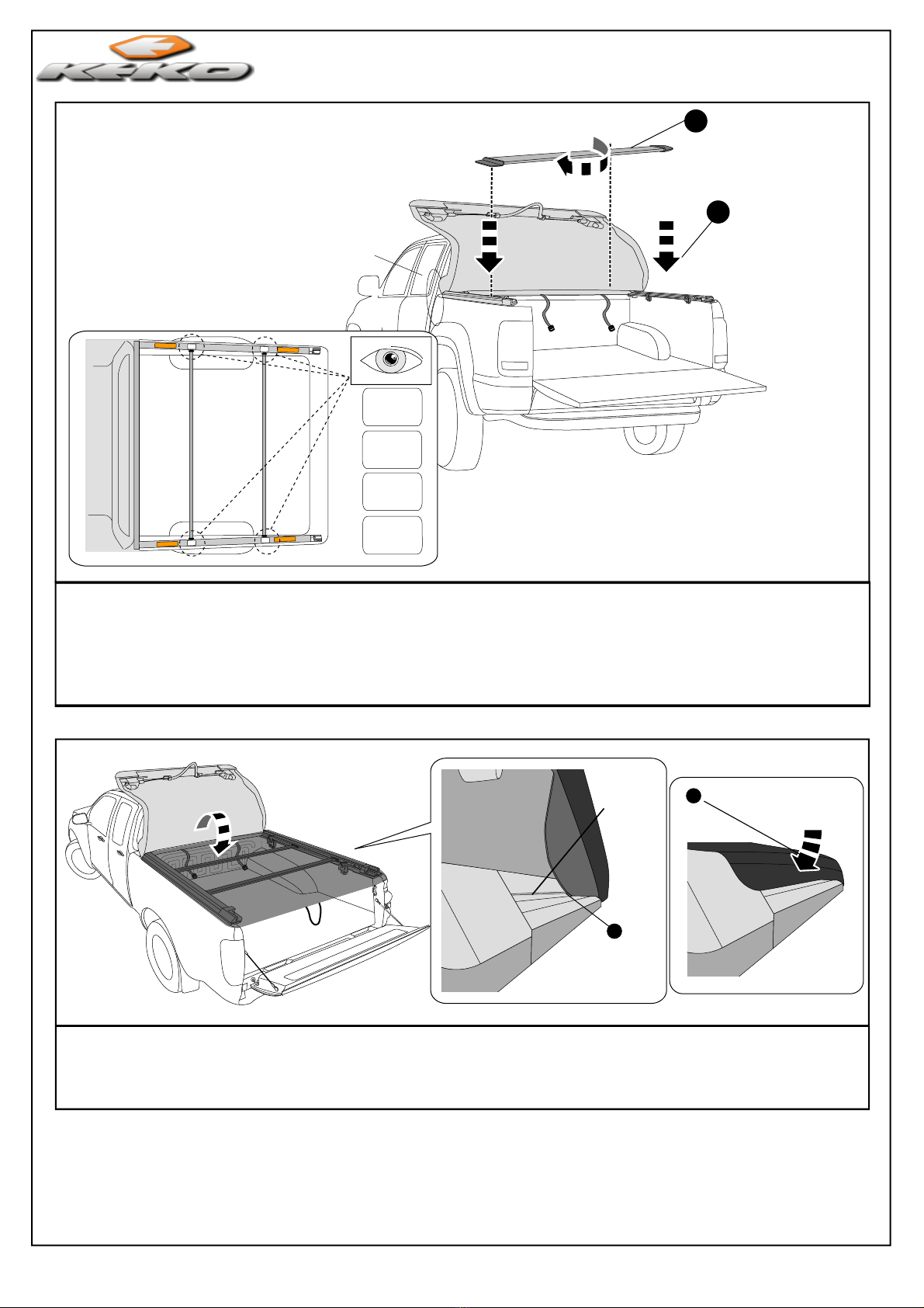
IMPORTANTE / IMPORTANT
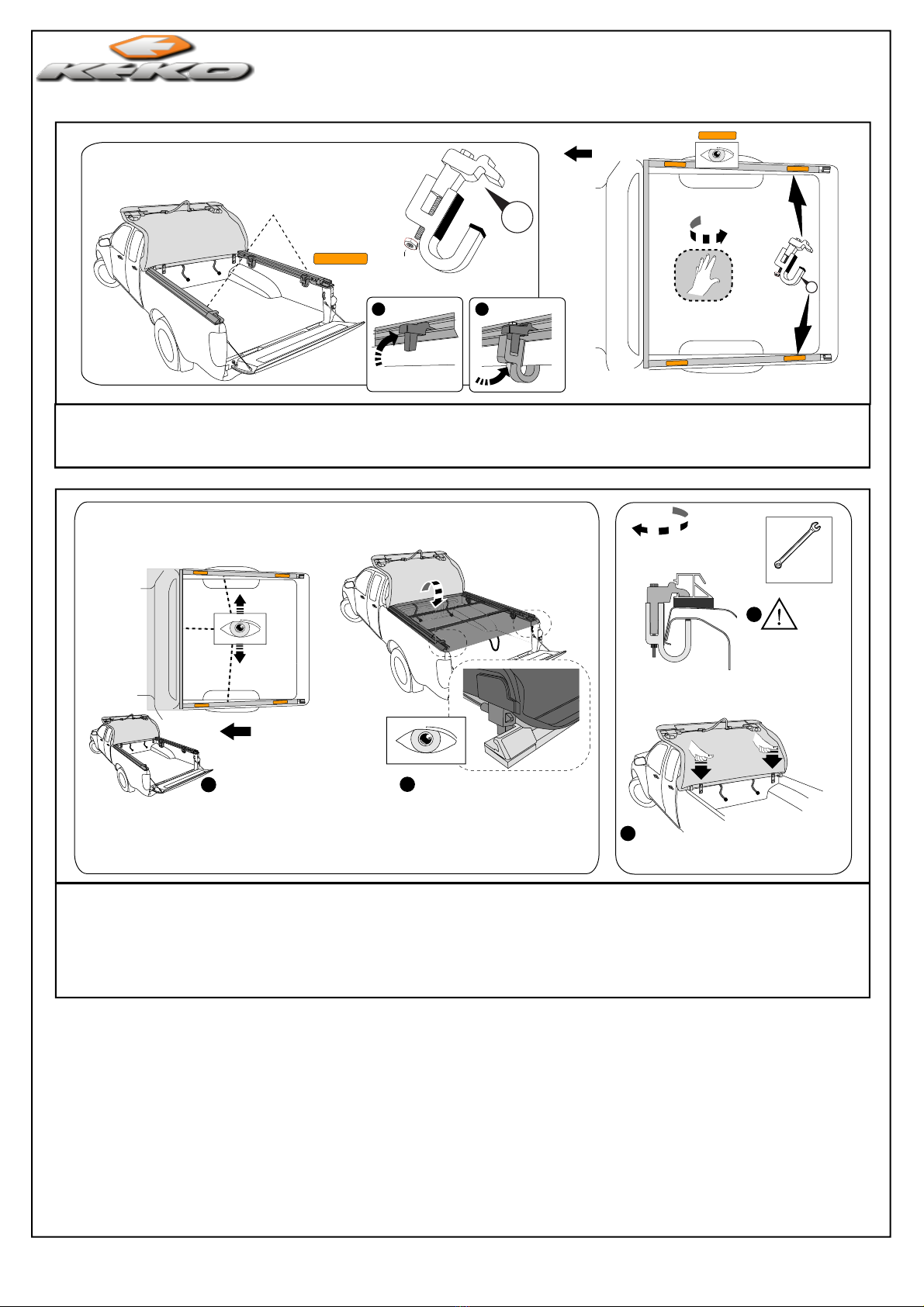
DO NOT CLOSE THE REAR TAILGATE WHEN TONNEAU COVER LATCHES ARE
ENGAGED.
When Closing the Vehicle Tailgate Ensure the Tonneau Cover Latches are Dis-engaged First,
then close the Tailgate.
Re-engage the Latches and ensure that the entire length of the Cover Side Flexible Flanges
are firmly located into the Side Rails as showed previously..
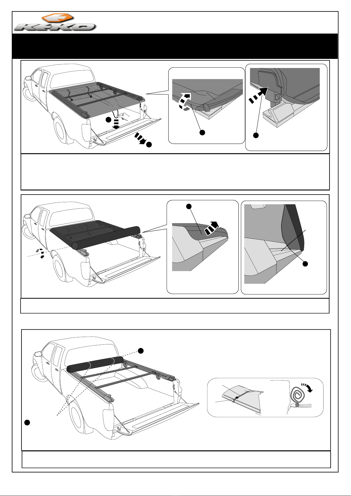
CLOSE REAR TAILGATE
ENGAGE LATCH &
PRESS DOWN UNTIL
LATCHES CLICK
CHECK COVER IS
LOCATED IN SIDE RAILS
4
3
DIS-ENGAGE LATCH
12
NÃO FECHE A TAMPA DA CAÇAMBA COM A CAPOTA MARÍTIMA TRAVADA.
Ao fechar a tampa traseira da caçamba do veículo, assegurar que as travas da capota tenham
Trave a Capota Marítima, mas antes assegure-se de que os perfis flexíveis estejam encaixados
Pressione firmemente, conforme indicado anteriormente.
sido destravadas antes.
corretamente.
DESTRAVAR FECHE A TAMPA DA CAÇAMBA
PRESSIONE OS TERMINAIS
P/ BAIXO ATÉ OUVIR O CLICK
VERIFIQUE SE A LONA
ESTÁ ENCAIXADA NOS
PERFIS LATERAIS
Keko Acessórios Ltda. warrants to the original purchaser of Keko's products, for the period of one year, from the date of the purchase, that the
product is free from defects in raw material, workmanship or finishing and it is Keko's obligation, under this warranty, to repair or replace, at
Keko's election, any part or parts of the product which prove to be defective.
This warranty shall not apply to any product which has suffered damage from collision, mishandling, misuse, incorrect cleaning, and incorrect
installation or to any product that has been altered from its original conception or had its serial number removed.
Maintenance, cleaning and durability:
For cleaning use only water, neutral soap and sponge or flannel. Periodically use automotive wax to conserve the chrome-plated parts. Never
use chemicals or abrasive products nott to scratch and expose the product to corrosion.
Warranty Registration Form: Fill in the form at www.keko.com.br
Warranty Claim: request the shop where the accessory was purchased to evaluate the defect. If proved to be Keko's liability, the part will be
repaired or replaced without charge. The repair or replacement of the parts will not result in extension of the warranty term provided.
Keko's Liability Term: Keko does not assume any responsibility for the mishandling or wrong installation of its products. Keko's products are
merely decorative and do not guarantee the safety of the occupant or vehicle in case of a rollover or other vehicle accident.
Keko Acessórios Ltda. concede ao comprador original dos produtos Keko garantia de um ano partir da data da compra original por defeito
de fabricação em matéria-prima, mão-de-obra ou acabamento, em serviço ou uso normal, sendo devidamente comprovados.
Excluem a garantia danos ocasionados por colisões, uso indevido do produto como sobrecarga, limpeza incorreta, instalação inadequada,
alteração da concepção original do produto ou n° de série de fabricação removido.
Conservação, limpeza e durabilidade:
Para limpeza utilizar somente água, sabão neutro,esponja ou flanela. Para conservação de produtos com acabamento cromo utilizar
periodicamente cera automotiva. Nunca utilizar produtos químicos ou abrasivos, dado que seus componentes riscam o acabamento e
expõe a corrosão os produtos com acabamento em cromo, e danificam os produtos em plástico.
Cadastro da garantia: preencher o cadastro através do site www.keko.com.br.
Solicitação da garantia: solicitar à loja em que foi efetuada a compra a avaliação do problema. Em caso de reclamação procedente, a
peça será substituída sem ônus ao proprietário. O conserto ou substituição das partes do equipamento não ocasionará prolongamento do
prazo de garantia estabelecido para o mesmo.
Termo de responsabilidade dos produtos Keko: a Keko não assume qualquer responsabilidade em virtude de ocorrências de qualquer
natureza, decorrentes da má utilização/instalação dos seus produtos. Os produtos Keko são comercializados como acessórios
meramente decorativos e não devem ser considerados como medida de proteção para o veículo ou passageiros em casos de
colisão ou capotagem.
GARANTIA / WARRANTY
30/07/13