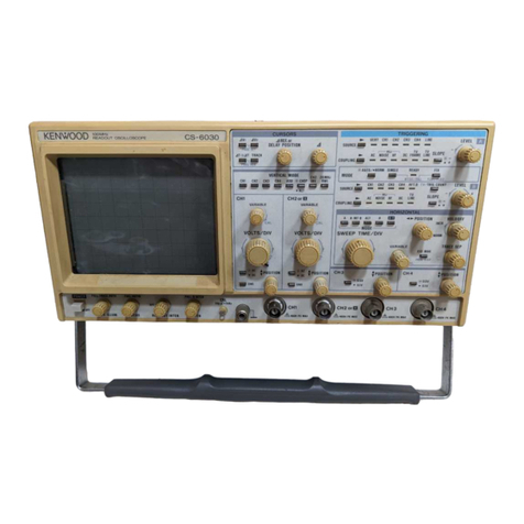
Kenwood CS-1352 User manual

TRIGGEREDSWEEPOSCILLOSCOPE
INSTRUCTION
MANUAL
CS-1352
DUAL
TRACEOSCILLOSCOPE

FEATURES
*Vertical
axis
provideshighsensitivityandwide
bandwidth,2 mV/div,15MHz(-3dB).
*OperatesonAC,internalDCandexternalDC,
each
beingselectedautomatically
without
using
powerselectorswitch.
*TheadoptionofIC's
throughout
circuitry
assures
highperformanceandimprovedreliability.
*ThehighvoitagepowerforCRTaswellasthe
powerforothercircuitsisfullystabilized,thus
thesensitivityandluminancearecompretely
free
from
effectsofvoltagevariations,
*X-Yoperationispossible
with
CH2amplifier
used
asX
axis.
The
horizontal
axis
sensitivityisashighas10
mV/div,
permitting
accuratecalibrations.
*Sumanddifferencebetween2 channelscanbe
measured
bytheuseofmodeselectorswitch
and
CH2selectorswitch.
CONTENTS
Page
Features
^
2
Specifications
Controlson
Panels
*
Operation^
Preliminary
Operation^
OperatingProcedures^
Power
Supply®
Battery
Charging8
Mounting
ofHood®
Applications^
Dual-trace
Applications^
Single-channel
Applications1^
FM
Receiver
Adjustments21
X-Y
OperationsApplications21
AmplifierSquareWave
Test
23
PRECAUTIONS
28
MAINTENANCE
AND
ADJUSTMENT
Maintenance28
Adjustment29
SCHEMATIC
DIAGRAM31
*Time
base
switchallowschangeoverbetween
CHOP
andALTandbetweenV (vertical)andH
(horizontal)ofTV
sync
separatorcircuit,
automaticallyandelectronically.
*At
AUTO
positionof
TRIG
LEVEL,
itispossibleto
check
theluminanceatno-sighaltimeandtoad-
just
triggering
levelof
input
waveforms.
*Theemploymentof
digital
switchcircuitand
mechanical
partscleverlymountedoncircuit
boards
assure
improvedreliability.
*Theover-dischargeprotectioncircuit
automaticallyshutsoffthebatterycircuitwhen
batteryvoltageislow.
*The
built-in
chargingcircuitpermitsthebattery
tobechargedwhiletheoscilloscopeisinuse.
1

SPECIFICATIONS
Type
ofCathodRayTube:
C331P31B
AccelerationVoltage:
Approx.1.5kV
VerticalAxis(for
both
CHIandCH2)
Sensitivity:
2
mV/div~10V/div,±5%in1-2-5sequence(1
div=0.6
cm)
Vernier
control
for
fully
adjustablesensitivity
betweensteps.
Input
Impedance:
1MS2
±5%.
Input
Capacitance:
Approx.22pF
Frequency
Response:
DC
DC-15MHz
(less
than-3dB)
AC
10Hz-15MHz
(less
than-3dB)
Rising
Time:
Less
than23nsec.
Over-shoot:
Less
than3%(at100kHzsquarewave)
Cross-talk:
Betterthan70dBat1 kHz
OperatingMode:
CH1:
Channel1
only
CH2:
Channel2
only
DUAL.
2-channel
(CHOP
andALTare
automaticallyselectedby
SWEEP
TIME/DIV)
0.5/xs/div~ 0.5ms/div:
ALT
(alternatesweep)
1
ms/div~
0.5s/div:
CHOP
ADD:
2-channelalgebraicsum(CH1+CH2)
InvertPolarity:
CH2
only
CHOP
Frequency:
200kHz±20%
Maximum
Input
AllowableVoltage:
600Vp-por300V(DC+ ACpeak)
SweepCircuit
Sweep
System:
Triggeredandautomatic.Inautomaticmode,
sweep
is
obtained
without
input
signal
Sweep
Time:
0.5;us/div~0.5s/div±5%in19rangesand
"X-Y",
in1-2-5sequence.
Each
overlapping
rangeprovidesforfineadjustament
Magnifier:
5
times±5%
(PULLx
5 MAG)
Linearity:
Betterthan3%(2)us/div~ 05s/div)
Betterthan5%(0.5jus/div~ 1/is/div)
Synchronization
Sync
Input:
INT:
Mode
switchchangeover,CH
1
at
DUAL
EXT
Sync
Selection:
NOR:
positiveandnegative
TV:
positiveandnegative
(TVH
andTVVareautomaticallyswitchedby
SWEEP
TIME/DIV)
TVH
(TV- Line):0.5Ms/div~ 50jts/div
TVV
(TV- Frame):0.1ms/div~ 50s/div
Sync
Range:
Sync
Position
Sync
Frequency
Min.syncvoltage
(amplitude)
Sync
Position
Sync
Frequency
INT
EXT
20Hz~5 MHz 05 div 0.5Vp-p
NOR
20Hz~10MHz
1
div 0.5Vp-p
20Hz-15MHz
1
div
1
Vp-p
(AUTO)
50Hz-15MHz
1
div
1
Vp-p
TV TV
signal
1
div
1
Vp-p
External
sync
input
voltage:
50V
(DC+ ACpeak)
HorizontalAxis(CH2
input)
OperatingMode:
X-Y
modeisselectedby
SWEEP
TIME/DIV
CH
1:Y
axis
CH2:
X
axis
Sensitivity:
Same
asCH1
(2
mV/div~ 10V/div± 5%)
Frequency
Response:
DC
DC-1MHz
(less
then
-3dB)
AC
10Hz-1MHz
(less
than-3dB)
Input
Impedance:
Same
asCH
1
(1M12±5%)
Input
Capacitance:
Same
asCH
1
Approx.22pF
CalibratingVoltage:
1
Vp-p±3%positive.(1kHz±5%squarewave)
Luminance
Modulation
Input
Voltage:
Lightsat+ 5Vor
less
2

Input
Impedance:
10kfi±20%
Frequency
Response:
DC
~ 1 MHz
Maximum
Input
AllowableVoltage:
50V
(DC+ ACpeak)
PowerSource
AC
Power
SupplyVoltage:
100/120/220/240V
±10%.50/60Hz
Power
Consumption:
Approx.25W
Battery(Option)
Power
SupplyVoltage:
12V
ContinuousOperationTime:
More
than2 hours
with
fully
chargedbattery
DC
Power
SupplyVoltage:
1
1
~ 15.5V
Power
Consumption:
Approx.20W
Charging
Charging
System:
InternalbatteryischargedbyconnectingAC
linecord
ChargingTime:
Charging
during
operationApprox.28H
ChargingonlyApprox.16H
AmbientTemperatureand
Humidity:
0~ 50°C,95%or
less
Dimensions
andWeight
Width:
210
mm
Height:
136
mm
Depth:
348
mm
Projectionsnotincluded.
Weight:
6.5kg
(without
battery)
8.3kg(withbattery)
Accessories
Probe:
PC-29
2
Damping1/10
Input
impedance10MQ
Input
capacitance
less
than18pF
Pin-plug:
1
Replacement
fuse:
0.5A2
1A
2
Hood
(BF-6) 1
External
powerconnectorplug1
InstructionManual:
1
copy
External
powerconnector
plug
1
Optional
accessories:
Shoulderbag(MC-75)
Batterypack
(BP-7E)
3

CONTROLS
ONPANELS
FRONT
PANEL
4
Fig.
1
SIDEPANEL
Fig.
2

1.
$
POSITION
a
VerticalpositionadjustmentforCH1traceand
Y
positionforX-Yoperation.Waveformscan
besettoanydesiredverticalposition.Turning
this
control
tothe
right
willshiftwaveformup-
ward,
andvice
versa.
2.
INPUT
Vertical
input
terminalofCH1(orY inX-Y
mode).
3.
AC-GND-DC
DC
Direct
input
ofACandDCcomponent
of
input
signal.
GND
Openssignalpathand
ground
input
to
verticalamplifier.
This
providesa zero-
signalbaseline,thepositionofwhich
can
beusedasa referencewhenper-
forming
DCmeasurements.
AC
BlocksDCcomponentof
input
signal.
4.
VARIABLE
Verticalattenuatoradjustmentprovidesfine
control
ofverticalsensitivity.Intheextreme
clockwise
(CAL)position,thevertical
attenuatoriscalibrated.
5.
VOLTS/DIV
VerticalattenuatorforChannel1;provides
coarse
adjustmentofverticalsensitivity.Ver-
ticalsensitivityiscalibratedin12steps
from
2
mVto10voltsperdivisitonwhen
VARIABLE
control
(4)issettotheCALposition.
6.
MODE(CH1,CH2,DUAL,ADD)
CH1:
Onlythe
input
signaltoCH1isdis-
playedasa singletrace.
CH2:
Onlythe
input
signaltoCH2isdis-
playedasa singletrace.
DUAL:
Intherangeof0.5s/divto
1
ms/div,
the
input
signalsto
both
channelsare
switchedbyabout200kHzsignal
(CHOP
operation).
Intherangeof0.5ms/divto
0.5ms/-
div,the
input
signalsto
both
channels
arealternatelyswitchedfor
each
sweep(ALToperation).
ADD:
Thewaveforms
from
Channel1 and
Channel
2 inputsareaddedandthe
sum
isdisplayedasa singletrace.If
thechannel2 polarityswitch(11)is
pulledout
(PULL
INV),thewaveform
from
Channel2 issubtracted
from
the
Channel
1 waveformandthe
differenceisdisplayedasa single
trace.
7.
VOLTS/DIV
VerticalattenuatorforChannel2 which
providesstepadjustmentofverticalsensitivi-
ty.Verticalsensitivityiscalibratedin12steps
from
2 mVto10voltsperdivisionwhen
VARIABLE
control
(8)issettoCALposition.
This
control
adjustshorizontalsensitivitywhen
the
SWEEP
TIME/DIVswitch(21)isintheX-Y
position.
8.
VARIABLE
Verticalattenuatoradjustmentprovidesfine
control
ofverticalsensitivityofCH2(orX).
This
control
becomesthefinehorizontalgain
control
whenthe
SWEEP
TIME/DIVswitchis
intheX-Yposition.
9.
AC-GND-DC
DC
Direct
input
ofACandDCcomponent
of
input
signal.
GND
Openssignalpathand
ground
input
to
verticalamplifier.
This
providesa zero-
signalbaseline,thepositionofwhich
can
beusedasa referencewhenper-
forming
DCmeasurements.
AC
BlocksDCcomponentof
input
signal.
10.
INPUT
Vertical
input
terminalforCH2(orX).
11.
A
POSITION,
X-Y^
VerticalpositionadjustmentforChannel2
trace.
Becomeshorizontalpositionadjust-
mentwhen
SWEEP
TIME/DIVswitch(21)isin
theX-Yposition.Push-pullswitchinverts
Channel
2 signalwhenpulledout(CH2
POLARITY
PULL
INV),non-invertedsignal
whenpushedin.
12.
POWER
LAMP
Lightswhenscopeison,dimswhenbatteryis
low,goesoffwhenbatteryistoolowfor
operation.
13.
CHARGE
LAMP
Lightswhenbatteryischarging,goesoffwhen
batteryis
fully
charged.Chargeroperates
whenever
scopeisconnectedtoACpower,
regardless
ofwhetherscopeisturnedonoroff.
14.
POWER/INTEN
Fully
counterclockwise
rotation
ofthis
control
(OFF
position)turnsoscilloscopeoff.
Clockwise
rotation
turnsoscilloscopeon.
Furtherclockwise
rotation
ofthe
control
increases
theintensityofthetrace.
5

15.
FOCUS
Spot
focuscontroltoobtainoptimum
waveformaccordingtobrightness.
16.
SOURCE
Selects
triggeringsourceforsweep.
INT:
Sweep
istriggeredbythewaveform
beingviewed:inDUALandADD
modes,
sweepistriggeredbyCH1
signal.
EXT:
Sweep
istriggeredbythesignal
appliedtoEXT
TRIG
jack(29).
17.
SYNC
Sync
separatorswitch.Itpicksup
sync
signal
componentinTVvideosignalandappliesto
sync
circuitforcompletesynchronizationof
videosignalbeingviewed.
NOR:
Usedforviewingallwaveformsex-
cepttelevisioncompositevideo.
TV:
The
sync
pulsesofa televisioncom-
positevideosignalareusedtotrigger
thesweep;thevertical
sync
pulses
(TVV-frame)
areautomatically
selected
forsweeptimesof05s/div.
to01ms/div.,andhorizontal
sync
pulses
(TVH-line)areautomatically
selected
forsweeptimesof50jus/div.
to0.5/Lts/div.
18.
SLOPE
Sunc
polarityselectorswitch.Atthe" + "
position,sweepiseffectedwithpositiveslope,
and
atthe" —"position,itiseffectedwith
negativeslope.
19.
TRIG.
LEVEL
Sync
leveladjustmentdeterminespointson
waveformslopewheresweepstarts;(—)
equals
mostnegative
point
oftriggeringand
(
+
)
equalsmostpositive
point
oftriggering.
PULL
AUTO:
Push-pull
switch
selects
automatictriggering
when
pulledout
(PULL
AUTO).
When
automatictriggering,a sweepisgenerated
without
aninputsignal.
20.
POSITION
Horizontalpositionadjustertoshiftwaveform
toanydesiredhorizontalposition.A
right
turn
oftheadjusterwillshiftthewaveformto
right,
and
vice
versa.
PULL
X5MAG:
Sweep
magnifierswitch.Bypullingtheknob
towardyou,waveformismagnifiedto5 times
inleftand
right
directions.Brightnessis
slightly
decreased.
21.
SWEEP
TIME/DIV
Horizontalcoarsesweeptimeselector.
Selects
calibratedsweeptimesof0.5/us/div.
to0.5s/div.,in19stepswhen
VARIABLE
control(22)issettotheCALposition(fully
clockwise).
IntheX-Yposition,thisswitch
disables
theinternalsweepgeneratorand
permitstheCH2inputtoprovidehorizontal
sweep.
22.
VARIABLE
Fine
sweeptimeadjustment.Intheextreme
clockwise
(CAL)position,thesweeptimeis
calibrated.
23.
CAL1 Vp-p
Provides
calibrated1 kHz,1 voltpeak-to-peak
square
wavecalibrationsignal.
This
isusedfor
calibrationoftheverticalamplifierattenuators
and
tocheckthefrequencycompensationad-
justmentoftheprobesusedwiththeos-
cilloscope.
24.
HANDLE
Use
thishandletomounttheoscilloscopeina
slant
position.
25.
AC
VOLTAGE
SELECTOR
The
CS-1352
maybeoperatedfrom100V,
120V,
220V,240V,
putting
theAC
VOLTAGE
SELECTOR
intheplaceofanother.
26.
FUSE
HOLDER
For
220~ 240Voperationa 0.5amperefuse
shouldbe
used.
For
100~ 120Voperationa 1 amperefuse
shouldbe
used.
27.
POWER
CONNECTOR
For
connectionofthesuppliedACpowercord.
28.
INTMOD
Intensity(brightness)modulationterminal.
Intensityismodulatedatvoltagesof+ 5V.
29.
EXT
TRIG
External
sync
inputterminal.Forexternal
syn-
chronization,setthe
SOURCE
switch(16)to
EXT
toapplyexternal
sync
voltage.
30.
ASTIG
Astigmatismadjustmentprovidesoptimum
brightnessandspotroundnesswhenusedwith
the
Focus
knob.Very
little
readjustmentof
thiscontrolisrequiredafterinitialadjustment.
31.
EXTDC
6

External
DCpowerjacktosupply11~
1
5.5V
DC
power.
32.
VOLTAGE
NAMEPLATE
Be
suretousevoltageandfusespecified.
33.
CORD
REEL
Used
towindpowercordwhentheos-
cilloscopeistobecarriedorstored.Italso
serves
asa standwhentheoscilloscopeis
used
in
upright
position.
OPERATION
PRELIMAINARY
OPERATION
Whenoperatingthisoscilloscope,refertopanelcontrolsandtheirfunctions.Whenstartingthisoscilloscope
set
initially,settheoperatingcontrolsasfollowsandthesetmaybeturnedonsafely.
Fig.
3
OPERATING
PROCEDURES
1.
Selectthe
position
ofthepowervoltage
selec-
tor
plug
asindicatedbythearrowmarks.Then
insertthesuppliedpowercordtothepower
connector.
2.
Turn
POWER/INTEN
(14)clockwise.The
poweristurnedtoONand
POWER
lamp(12)
lights.
3.
Horizontal
axis
will
bedisplayed.Whenfly-
back
linedoesnotappearatthecenterofthe
screen,
adjust^
POSITION
(1)and
^•POSITION
PULL
X5MAG(20).
Adjustbrightnessby
POWER/INTEN
(14).If<-
tracelineisunclear,adjust
FOCUS
(15).
4.
Theoscilloscopeisnowreadyformeasure-
ment.Formeasurement,proceedasfollows:
Applysignalvoltagetothe
input
terminals(2)
and(10).Then
turn
the
VOLT/DIV
(5),
clockwise
until
thewaveformiscorrectlydis-
playedonthe
screen.
BysettingtheMODE
switch(6)toCH1andthe
SOURCE
switch
(16)
toINT,theCH1
input
signalto
INPUT
ter-
minal(2)
will
appear.WhentheMODEswitch
(6)
issettoCH2,thenthe
input
signalto
INPUT
terminal(10)
will
appearonthescope.
WhentheMODEswitch(6)issetto
DUAL,
twowaveforms(CH1andCH2)
will
appearon
thescope,atthistime,theCH1signaltothe
INPUT
terminal(2)isfedtothesyncrocircuit
wheretheCH
1
signalissynchronized.When
theMODEswitch(6)issettoADD,theCH1
signalisalgebraicallyaddedtotheCH2signal
(CH
1
+ CH2).By
pulling
CH2
POLARITY
(11),
theCH2signalinreverse
polarity
isadd-
edtotheCH1signalandthealgebraic
7

differencebetweenCH1andCH2isdisplayed
(CH1
- CH2).
5.
Whenthesignalvoltageismorethan2mVand
waveformfailstoappearonthe
screen,
theos-
cilloscope
maybecheckedbyfeedinginput
fromCAL1 Vp-p(23).
Since
calibration
voltageis1 Vp-p,thewaveformbecomes5 div
highatthe0.2/divposition.
6.
Bypushing
TRIG
LEVEL
(19).thefree-running
autofunctionis
released.
Thewaveformdis-
appears
whentheknobisturnedclockwise,
and
appearsagainwhenitisreturnedtoitsap-
proximatemiddlepositionofit.
Sync
phaseis
also
adjustableinthis
case.
Thewaveformwill
again
disappearwhentheknobisturned
counterclockwise
fromthemidposition.
7.
WhenDCcomponentismeasured,set
AC-GND-DC
(3)or(9)toDCposition.If,in
this
case,
theDCcomponentcontainsplus
"+ " potential,thewaveformmovesupward
and
ifitcontainsminus" —"potential,the
waveformmovesdownward.
The
reference
point
of"0"potentialcanbe
checked
atGNDposition.
POWER
SUPPLY
The
oscilloscopeisdesignedtooperateonAC,in-
ternalbatteryorexternalDC.
AC
operation
For
ACoperation,firstsetthepowervoltage
selec-
torswitchtothevoltageofyourlocalACcurrent.
Then,
connecttheACcord.Theconnectionofthe
AC
cordautomaticallydisconnectstheinternal
battery.
Operationoninternalbattery(option)
Install
thebatterypackintheoscilloscopeaccoring
tothefollowingsequence(refertothediagramon
therearofthe
case):
*OpenthepackageofthebatterypackBP-7(op-
tion)andchecktomakesurethatitcontainstwo
6V
leadbatteriesandconnecting
leads.
*
Place
theoscilloscopewiththeupsidedown,
removethe4
screws
on
both
sides
usinga
screwdriver.
Holdthecordreelandpullitout.
The
battery
case
coverwillberemoved.
*
Release
theleadfromthecordclamperandthen
removethescrew(4x 40mm)asshowninthe
diagram.
*Connectthe2 batteriesin
series
usingthecon-
necting
leads,
thenconnecttheleads(redand
black)
oftheoscilloscopetothebatteries.Make
sure
thattheredleadisconnectedto"+"and
theblackleadto" —"side.
*Afterthebatterieshavebeenconnected,insert
thebattery
case
fromtherearandreplacethe
battery
case
cover.Thebatteryleadsshouldbe
arranged
ontopofthebatteriessothattheyare
notcaughtbetweenthebatteriesandthebattery
case.
*Tightenthe4
screws
fromeachsideofthe
case
and
thescrew(4x 40mm)fromtherearofthe
case.
Now,theoscilloscopeisreadyforoperation.
Refer
totheinstructionsinthepreviousparagraph
"Con-
trolson
Panels".
Withtheinternalbattery,theos-
cilloscope
canbeoperatedformorethan2 hours,
althoughthisdependsontheconditionofthe
battery.
When
thebatteryvoltagefallsdownto10Vduring
operation,theprotectioncircuitisactivatedtoshut
offthebatterycircuit.Inthis
case,
thepowerlamp
goes
offindicatingthatthebatteryisprotected
against
over-discharge.Whenthishappens,the
batteryshouldberechargedfullyandimmediately,
(refer
toitem"BatteryCharging")
The
powerlampwillstartblinkingtoindicate
batteryvoltagedrop10minutesbeforetheprotec-
tion
circuitoperates.
OperationonexternalDC(11~
15.5V)
Connect
a DCpowercordfromDC12Vreceptacle
(31)
toa nominal12voltDCpowersource(11to
15.5
VDC),suchasa vehiclecigarettelighter.
Observe
properpolarity;theoscilloscopeis
protectedagainstreversepolaritydamage,butwill
notoperateifpolarityis
reversed.
Turn
on
POWER/INTEN
control(14).
POWER
indicator(12)shouldglow,andthescope
is
readyforuse.
If
CHARGE
indicator(13)glows,thebatteriesare
chargingtheindicatorgoesoffwhenthebatteries
are
fullycharged.
BATTERY
CHARGING
To
chargetheinternalbattery,connecttheACline
cordtoACoutlet.Thebatteryischarged
regardless
ofthepositionofthepowerswitch.
When
batterychargeisstarted,the
CHARGE
lamp
will
light.
Withthepowerswitchsetto
OFF,
the
batteryisfullychargedinabout16hours.Withthe
switch
settoON,thebatteryischargedinabout
28
hours;theoscilloscopecanbeusedwhilethe
batteryisbeingcharged.Theexternalpowercon-
8

nectorplugmustbedisconnectedwhilethebattery
is
beingcharged.
Whenthebatteryisalmostfullycharged,the
CHARGE
lampbecomesdimandfinallygoesoff.
Continuechargingforabout2 hours,thenthe
batterywillhavebeenfullycharged.
MOUNTINGOFHOOD
The
suppliedhoodcanbemountedontheos-
cilloscopeasshowninFig.4.
APPLICATIONS
DUAL-TRACE
APPLICATIONS
Introduction:
The
mostobviousandyetthemostusefulfeature
ofthedual-traceoscilloscopeisthatithasthe
capabilityforsimultaneouslyviewingtwo
waveforms
thatarefrequency-orphase-related,or
thathavea commonsynchronizingvoltage,suchas
in
digital
circuitry.Simultaneousviewingof
input
andits
output
isaninbaluableaidtothecircuit
designerortherepairman.
Several
possible
applicationsofthedual-traceoscilloscopewillbe
reviewed
indetailtofamiliarizetheuserfurtherin
thebasicoperationofthisoscilloscope.
Frequency
DividerWaveformsViewing:
Fig.
5 illustratesthewaveforminvolvedina basic
divide-by-twocircuit.Fig.A indicatesthe
reference
orclockpulsetrain.Fig.B andFig.C in-
dicatethepossibleoutputsofthedivide-by-twocir-
cuitry.Fig.5 alsoindicatesthesettingsofspecific
oscilloscopecontrolsforviewingthesewaveforms.
In
addition
tothesebasiccontrolsettings,the
TRIGGERING
LEVEL
control,aswellasthe
Channel
1 andChannel2 verticalpositioncontrols
shouldbesetasrequiredtoproducesuitabledis-
plays.
InthedrawingofFig.5 thewaveform
levels
of2 divareindicated.Ifexactvoltage
measurements
ofChannel1 andChannel2 are
desired,
theChannel1 andChannel2
VARIABLE
controlsmustbeplacedintheCALposition.The
Channel
2 waveformmaybeeitherthatindicated
inFig.5BorFig.5C.InFig.5C,thedivide-by-
two
output
waveformisshownforthe
case
where
the
output
circuitryrespondstonegative-going
Fig.
5 Waveformsindivide-by-twocircuit.
9
HOOD
BEZEL
INSERT
CLAWS
INTO
4
HOLES
Fig.
4 MountingofHood
CH
1
A.
REFERENCE
FREQUENCY
PULSE
TRAIN(1000
PULSES
PERSECOND)
LEADING
EDGES
MAYNOTBE
VISIBLE
AT
FAST
SWEEP
RATES
CH
2
B.
DIVIDE-BY-TWOOUTPUTSYNCHRONIZEDTO
LEADING
EDGE
OF
REFERENCE
PULSE
CH
2
C.
DIVIDE-BY-TWOOUTPUTSYNCHRONIZEDTO
TRAILING
EDGE
OF
REFERENCE
PULSE

waveform.Inthis
case,
the
output
waveformis
shifted
with
respecttotheleadingedgeofthe
reference
frequencypulsebya timeintervalcor-
respondingtothepulsewidth.
Divide-by-8CircuitWaveforms:
Fig.
6 indicateswaveformrelationshipsfora
basic
divide-by-eightcircuit.Theoscilloscopesettings
are
identicaltothoseusedinFig.5.The
reference
frequencyofFig.6Aissuppliedtothe
Channel
1
input.
Fig.6Bindicatestheidealtime
relationshipbetweenthe
input
pulsesandthe
out-
putpulse.
Inanapplicationwherethelogiccircuitryis
operatingatornearitsmaximumdesignfrequency,
theaccumulatedrisetimeeffectsofthecon-
secutive
stagesproducea
built-in
timepropagation
delay
whichcanbesignificantina criticalcircuit
andmustbecompensatedfor.Fig.6Cindicates
thepossibletimedelaywhichmaybeintroduced
into
a frequencydividercircuit.Byuseofthedual-
trace
oscilloscope,the
input
and
output
waveforms
can
besuperimposed(ADDorSUB)todetermine
theexactamountofpropagationdelaythatoccurs.
A.
REFERENCE
FREQUENCY
PULSE
TRAIN
(1000
PULSES
PER
SECOND)
B.
IDEAL
DIVIDEBYEIGHTOUTPUT
PropagationDelayTimeMeasurement:
Anexampleofpropagationdealyina divide-by-
eightcircuitwasgiveninthepreviousparagraph.
Significantpropagationdelaymayoccurinanycir-
cuit.
This
oscilloscopehasfeatureswhichsimplify
measurementofpropagationdelay.Fig.7 shows
theresultantwaveformswhenthedual-trace
presentationiscombined
into
a single-trace
presentationbyselectingtheADDorSUB(CH2
POLARITY
PULL
INV)positionoftheMODE
switch.
IntheADDpositionthetwoinputsare
algebraicallyaddedina single-tracedisplay.
Similarly,
intheINV.(pull)positionthetwoinputs
are
algebraicallysubtracted.Eitherposition
providesa precisedisplayofthepropagationtime
(Tp).
Usingtheproceduregivenforcalibratedtime
measurement
(CAL),
Tpcanbemeasured.A more
10
precise
measurementcanbemeasured.A more
precise
measurementcanbeobtainediftheTp
por-
tion
ofthewaveformisexpandedhorizontally.
This
may
bedoneby
pulling
theX5MAGcontrol.It
also
maybepossibletoviewthedesired
portion
of
thewaveformata fastersweep
speed.
EXPAND
THISPORTION
FOR
TIMEMORE
PRECISE
MEASUREMENT
DigitalCircuitTimeDelayMeasurement:
Since
a dual-traceoscilloscopehasthecapabilityof
comparingthe
timing
ofonewaveform
with
another,itisnecessityindesigning,manufacturing
andservicing
digital
equipment.In
digital
equip-
ment,itiscommonfora largernumberofcircuits
tobesynchronized,ortohavea specifictime-
relationshiptoendother.Manyofthecircuitsare
frequencydividersaspreviouslydescribed,but
waveforms
are
often
time-relatedinmanyother
combinations.Inthedynamicstate,someofthe
waveforms
changedependinguponthe
input
or
moreofoperation.Fig.8 showsa typical
digital
cuicuitandidentifies
several
ofthepointsatwhich
waveformmeasurementsareappropriate.Theac-
companyingFig.9 showsthenormalwaveformsto
beexpectedateachofthesepointsandtheirtim-
ingrelationship.Theindividualwaveformshave
limited
valueunlesstheir
timing
relationshiptoone
ormoreoftheotherwaveformsisknowntobecor-
rect.Thedual-traceoscilloscopeallowsthiscom-
parisontobemade.Intypicalfashion,waveform
No.3 wouldbedisplayedonChannel1 and
C.
PROPAGATION
DELAY
INDIVIDEBY
EIGHT
CIRCUIT
Fig.
6 Waveformsindivide-by-eightcircuit
Fig.
7 UsingADDorSUBmodesfor
propagationtimemeasurement
CH1
CH2
ADD
SUB

Fig.
8 Typical
digital
circuitusingseveral
time-related
waveforms
11

waveformsNo.4
through
No.8 andNo.10,would
bedisplayedonChannel2 althoughother
timing
comparisonsmaybedesired.
WaveformsNo.11
through
No.13wouldprobably
bedisplayedonChannel2 inrelationshipto
waveformNo.8 orNo.4 onChannel1.Inthe
familyoftime-relatedwaveformsshowsinFig.9,
waveformNo.8 orNo.10isanexcellentsync
source
forviewingallofthewaveforms;thereis
butone
triggering
pulseperframe.Forcon-
venience,
externalsyncusingwaveformNo.8 or
No.10asthesyncsourcemaybedesiable.
With
No.8 orNo.10usedasexternalsyncsource.
any
ofthewaveformsmaybedisplayed
without
readjustmentofthe
TRIGLEVEL
control.
WaveformsNo.4
through
No.7 shouldnotbeused
as
thesyncsourcebecausetheydonotcontaina
triggering
pulseatthestartoftheframe.Itwould
notbenecessarytoviewtheentirewaveformsas
showninFig.9 inall
cases.
Infact,therearemany
timeswhena closerexaminationofa
portion
ofthe
waveformswouldbeappropriate.Insuch
cases,
it
is
recommended
that
thesyncremainunchanged
whilethesweepspeedorX5MAG
control
isused
toexpanedthewaveformdisplay.
1START
3
CLOCK
4DATA
SELECT
"A"
5DATA
SELECT
"B"-
6DATA
SELECT
"C"•
7DATA
SELECT
"D"
8DATE
ENABLE•
9
RUN
12
LINE
DRIVER
O.UTPUT'
13
ANYINDIVIDUAL
ADDRESS
ORFUNCTION
DATABITMAYBEPOSITIVEORNEGATIVE
DEPENDING
UPONTHECODEDINPUT
Fig.
9 Familyoftime-relatedwaveforms
from
typicaldigitalcircuitinFig.8
12
2COUNTER
ENABLE
10ENDFRAME
RESET
I
11MULTIPLEXER
OUTPUT

DistortionMeasurement:
An
amplifierstage,oranentireamplifier
unit,
may
betestedfor
distortion
with
thisoscilloscope.
This
measurement
isespeciallyvariablewhentheslope
ofa waveformmustbefaithfullyreproducedbyan
amplifier.Fig.10showsthetestingofsucha cir-
cuitusinga triangular
wave,
suchasistypicallyen-
counteredintherecoveredaudio
output
ofa
limiting
circuitwhichprecedesthemodulatorofa
transmitter.Themeasurementmaybemadeusing
any
typeofsignal;merelyusethetypeofsignalfor
testingthatisnormallyappliedtotheamplifierdur-
ingnormaloperation.Theprocedurefor
distortion
testingisasfollows:
SUB=DISTORTION
ADJUST
POSITION
CONTROLS
TO
SUPERIMPOSE
WAVEFORMS
DIRECTLY
OVER
EACH
OTHER
ADJUST
TOBOTH
WAVEFORMS
ARE
SAME
AMPLITUDE
1.
Applythetypeofsignalnormallyencountered
intheamplifierundertest.
2.
ConnectChannel1 probetothe
input
ofthe
amplifierandChannel2 probetothe
output
of
theamplifier.Itispreferableifthetwosignals
are
notinvertedinrelationshiptoeachother
butinvertedsignalscanbe
used.
3.
SetChannel1 andChannel2
DC-GND-AC
switches
toAC.
4.
SettheMODEswitchto
DUAL.
5.
Set
SYNC
SLOPE
switchtoINTandadjust
controlsasdescribedinwaveformveiwing
procedureforsynchronizingwaveforms.
6.
AdjustCH1andCH2
POSITION
controlsto
superimpose
thewaveformsdirectlyovereach
other.
7.
AdjustCH1andCH2verticalsensitivitycon-
trols
(VOLTS/DIV
and
VARIABLE)
sothatthe
waveforms
areaslargeaspossible
without
ex-
ceeding
thelimitsofthe
scale,
andsothat
both
waveformsareexactlythesame
hight.
8.
Now,settheModeswitchtoADDandCH2
Polarity
ofINV(ifonewaveformisinvertedin
relationshiptotheother,usetheNOR
position).
Adjustthefineverticalsensitivitycontrol(CH2
VARIABLE)
slightlyfortheminimumremain-
ingwaveform.Anywaveformthatremains
equals
distortion;ifthetwowaveformsareex-
actly
thesameamplitudeandsamewaveform
and
thereisnodistortion,thewaveformswill
cancel
andtherewillbeonlya straight
horizontallineremainonthe
screen.
Gated
Rising
Circuit(burstcircuit)
Fig.
11showsa burstcircuit.The
basic
settingsof
controlknobsarethesameasthoseinFig.5.The
waveformA isthereferencewaveformandis
appliedtoCH1
input.
Allotherwaveformsare
sampled
atCH2andcomparedtothereference
waveforms
aresampledatCH2andcomparedto
thereferencewaveformof
CH1.
Theburstsignal
13
AMP
No.1 AMP
No.2
Fig.
10Distortionmeasurement
Fig.
11Gatedringingcircuitandwaveforms

can
beexaminedmorecloselyeitherbyincreasing
thesweep
time
orby
pulling
the
POSITION
control
to
obtain
5 timesmagnification.
Delay
Line
Test:
The
dual-tracefeatureoftheoscilloscopealsocan
beusedtodeterminethedelaytimesoftransmis-
siontypedelaylinesaswellasultrasonictype
delaylines.The
output
ofdelaylinescanbe
observedonCH2whilebeingsynchronized
with
the
input
pulseof
CH1.
A repetitivetypepulse
will
makeitpossibletosynchronizethedisplays.The
intervalbetweenrepetitivepulsesshouldbelarge
comparedtothedelay
time
tobeinvestigated.In
addition,todeterminingdelaytime,thepulsedis-
tortion
inherentinthedelaylinecanbedetermined
byexaminationofthedelaypulseobservedonCH2
waveformdisplay.
Fig.
12demonstratesthetypicaloscilloscopeset-
tingsaswellasthebasictestcircuit.Typical
input
and
output
waveformsareshownontheos-
cilloscopedisplay.A commonapplicationofdelay
linechecksis
found
incolorTVreceivers.Fig.13
shows
theoscilloscopesettingsandtypicalcircuit
connectionstocheckthe"Y"delaylineemployed
inthevideoamplifiersection.The
input
waveform
and
output
waveformarecomparedfordelaytime,
usingthehorizontalsyncpulseofthecomposite
videosignalforreference.Theindicateddelayis
approximatelyonemicrosecond.In
addition
to
determiningthedelaycharacteristicsoftheline,
the
output
waveformreveralsany
distortion
that
maybeintroduced
from
animpedancemismatchor
a
greatlyattenuated
output
resulting
from
anopen
line.
CH
-1
(INPUT
PULSE)
CH
2
(OUTPUT
PULSE)
PULSE
GENERATOR
5000PPS
tjj.
sec.
PULSE
WIDTH INPUT
ULTRA
SONIC
DELAY
LINE
(5Msec)
OUTPUT
Fig.
12Delaylinemeasurements
VIDEO
AMPLIFIER
•NOTE:
SETTINGOF
VERTICAL"
tATTENUATORS SHOULDBE
THE
SAME,BUTMAYVARY
WIDELY,
DEPENDINGONCIRCUIT
TYPE.
TO
VIDEOOUTPUT
AMPLIFIER
NOTE:
NO
ELECTRICAL
CONNECTION:
PLACE
CLIP
ONINSULATIONOF
PLATE
CAP
LEAD
ORIN
CLOSE
PROXIMITYOF
HORIZONTAL
AMPLIFIER
TUBE.
14
Fig.
13Checking"Y"delaylineincolortelevisionreceivers
USE
1/10
PROBE
FOR
BOTH
CHANNELS
TO
HORIZONTAL
AMPLIFIER
CH
1 (INPUT)
CH
2 (OUTPUT)
1jLtS
DELAY
EXT
TRG
ON
SIDE
PANEL

Stereo
AmplifierServicing:
Anotherconvenientusefordual-traceoscilloscope
is
in
troubleshooting
stereoamplifiers.Ifidentical
amplifiersareusedandthe
output
ofoneisweak,
distorted
orotherwiseabnormal,thedual-traceos-
cilloscopecanbeefficientlyusedtolocalizethe
defectivestate.
With
anidenticalsignalappliedto
theinputsof
both
amplifiers,a side-by-sidecom-
parisonof
both
unitscanbemadebyprogressively
samplingidenticalsignalpointsin
both
amplifiers.
Whenthedefectiveormalfunctioningstagehas
beenlocatedtheeffectsofwhatever
troubleshooting
andrepairmethodsareemployed
can
beobservedandanalyzedimmediately.
improvingtheRatioofDesiredtoUndesired
Signals:
Insomeapplications,thedesiredsignalmaybe
riding
ona largeundesiredsignalcomponentsuch
as
60Hz.Itispossibletominimizeorforpractical
purposeeliminatetheundesiredcomponent.Fig.
14showstheoscilloscope
control
settingsforsuch
an
application.ThewaveformdisplayofChannel1
indicatesthedesiredsignalandthe
dotted
linein-
dicates
theaverageamplitudevariationcorrespon-
ding
toanundesired60Hzcomponent.The
Channel
2 displayindicatesa waveformofequal
amplitudeandidenticalphasetotheaverageofthe
Channel
1 waveform.
With
theMODEswitchset
toADD,andtheCH2signalinverted,andbyad-
justingtheCH2verticalattenuatorcontrol,the60
Hz
componentoftheChannel1 signalcanbe
cancelled
bytheChannel2
input
andthedesired
waveformcanbeobserved.
ADJUST
FORONE
COMPLETE
CYCLE
AT
60Hz
"SLOPE
+
Amplifier
Phase
ShiftMeasurements:
Phase
measurementscanbemadebyseveral
methodsusingoscilloscope.Typicalapplications
are
incircuitsdesignedtoprocedurea specific
shift,andmeasurementofphaseshift
distortion
in
audioamplifiersandnetworks.
Inallamplifiers,a phaseshiftisalwaysassociated
with
a changeinamplituderesponse.Forexample,
atthe—3dBresponse
point,
a phaseshiftof45°
occurs.
Fig.15illustratesa
method
ofdetermining
amplifierphaseshiftdirectly.Inthis
case,
the
measurementsarebeingmadeatapproximately
5000
Hz.The
input
signaltotheaudioamplifieris
used
asa referenceandisappliedtotheChannel1
input
jack.
The
VARIABLE
control
isadjustedasrequiredto
providea completecycleofthe
input
waveform
displayedon8 divhorizontally.A waveformheight
of2 divis
used.
The8 divdisplayrepresents360°
atthedisplayedfrequencyandeachcentimeter
represents
45°ofthewaveform.
The
signaldeveloped
across
the
output
oftheaudio
amplifierisappliedtotheCH2
input
jack.
The
verticalattenuatorcontrolsofChannel2 are
adjustedasrequiredtoproducea peak-to-peak
waveformof2 divasshowninFig.15B.The
Channel
2
POSITION
control
isthenadjustedso
that
theChannel2 waveformisdisplayedonthe
same
horizontal
axis
astheChannel1 waveformas
ADJUST
AS
REQUIRED
FOR
COMPLETE
CYCLE
IN8div
OUTPUT
•LOAD
Fig.
14
Improvingdesired-to-undesiredsignalradio
Fig.
15Measureringamplifierphaseshift
15
SIGNAL
60
Hz
START
WITH
DUAL
CHANGE
TOSUB
AF
SIGNAL
GENERATOR
INPUT
AUDIO
AMPLIFIER

showninFig.15B.Thedistancebetweencor-
respondingpointsonthehorizontal
axis
forthetwo
waveforms
thenrepresentsthephaseshift
betweenthetwowaveforms.Inthis
case,
thezero
crossover
pointsofthetwowaveformsarecom-
pared.
Itisshownthata differenceof1 div
exists.
This
istheninterpretedasa phaseshiftof45°.
Television
Servicing:
Manyofthevideoservicingprocedurescanbeper-
formedusingsingle-traceoperation.
These
are
outlinedlaterintheapplicationssectioncovering
single-traceoperation.Oneoftheseprocedures,
viewingthe
VITS
(verticalintervaltestsignal),can
beaccomplishedmuchmoreeffectivelyusinga
dual-traceoscilloscope.Asoutlinedinthesingle-
trace
applicationssectionandasshowninFig.19
and26,theinformationontheField1 andField2
verticalblankingintervalpulseisdifferent.
This
is
shownindetailinFig.19.Also,becausetheos-
cilloscopesweepissynchronizedtothevertical
blankingintervalwaveform,theField1 andField2
waveforms
aresuperimposed
onto
eachother.
Withdual-traceoperation,thesignalinformation
oneachblankingpulsecanbeviewedseparately
without
overlapping.Fig.18indicatestheos-
cilloscopecontrolsettingforviewingthealternate
VITS.
Mostnetworktelevisionsignalscontain
built-in
testsignals
(VITS)
thatcanbeveryvaluabletoolsin
troubleshootingandservicingvideoequipment.
The
VITS
canlocalize
trouble
totheantenna,tuner,
IF
orvideosectionsandshowswhenrealignment
may
berequired.The
VITS
signalisbeingusedin
some
televisionreceiversforautomaticcolorcor-
rection.
The
VITS
signalistransmittedduringthevertical
blankinginterval.Onthetelevisionset,theycanbe
seen
asa
bright
whitelineabovethetopofthepic-
ture,whentheverticallinearityorheightisad-
justedtoviewtheverticalblankinginterval.(OnTV
sets
with
internalretraceblankingcircuits,the
blankingcircuitmustbedisabledtoseethese
signals.)
The
transmitted
VITS
isprecisionsequencesof
specific
frequencies,amplitudesandwaveshapes
as
showninFig.16.Thetelevisionnetworksuse
theprecisionsignalsforadjustmentandchecking
ofnetworktransmissionequipment,butthetechni-
cian
canusethemtoevaluatetelevisionsetperfor-
mance.
Thefirstframeof
VITS
atthe"B"section
(line18)inFig.16begins
with
a whitereference
16
Fig.
16VITSsignal.Fields1 and2
(MULTI-BURST)
VERTICAL
BLANKINGINTERVAL(NO:1 ~ NO.21)
HORIZ.
SYNC.
PULSE
VERTICAL
BLANKINGINTERVAL(NO.263~ NO.282)
(MULTI-BURST)
FIELD
I
FIELD
2
FIELD
I&2
LINE
No.17 No.
18
No.279 No.280
No.
17
No.279 No.
18
No.280

signal,
followedbysinewavefrequenciesof0.5
MHz,
1.0MHz,2.0MHz,3.0MHz,4.0MHzand
3.58MHz.
This
sequenceoffrequenciesiscalled
the"multi-burst".
This
multi-burst
portion
ofthe
VITS
isthe
portion
thatcanbemostvaluabletothetechnician.The
second
frameofthe
VITS
(lines18and280),which
contains
thesine-squaredpulse,windowpulseand
the
staircase
of3.58MHzburstsatprogressively
lightershading,arevaluabletothenetwork,but
have
less
valuetothetechnician.As
seen
onthe
television
screen,
field1 isinterlacedwithfield2 so
thatline17isfollowedbyline279andline18is
followedbyline280.The
VITS
appearsattheend
oftheverticalblankingintervalandjustbeforethe
firstlineofvideo.
Nowtoanalyzethewaveform.Allfrequenciesof
themulti-burstaretransmittedatthesame
level,
butshouldnotbeequallycoupledthroughthe
receiver
duetoitsresponsecurve.Fig.28shows
thedesiredresponsefora goodcolortelevision
receiver,
identifyingeachfrequencyofthemulti-
burstandshowingthesllowableamountof
attenuationfor
each.
Rememberthat— 6 dB
equals
halfthereferencevoltage(the2.0MHz
modulationshouldbeusedforreference).
To
localizetrouble,startbyobservingthe
VITS
at
thevideodetector.
This
willlocalizetroubletoa
point
eitherbeforeorafterthedetector.Ifthe
multi-burstisnormalatthedetector,checkthe
VITS
onotherchannels.Ifsomechannelslook
okay
butothersdonot,youprobablyhavetuneror
antenna-system
troubles.Don'toverlookthe
IF
AMP
VIDEO
DETECTOR
TELEVISION
SET
VIDEO
AMP
SOUND
IF
COLOR
IF
Fig.
18Set-upforviewingfields1 and2 ofVITSinformation
17
RESPONSE-dB
FREQUENCY—MHz
Fig.
17
Color
TVIFamplifierresponsecurve
chance
oftheantennasystemcausing"holes"or
tilted
responseonsomechannels.Ifthe
VITS
is
abnormalatthevideodetectoronall
channels,
the
troubleisprobablyintheIFamplifier
stages.
As
anotherexample,letus
assume
thatwehavea
set
onthebenchwitha verypoorpicture.Ouros-
cilloscope
showsthe
VITS
atthevideodetectorto
beaboutnormalexceptthattheburstat2.0MHz
is
lowcomparedtotheburstsoneitherside.
This
suggests
anIFtrapisdetuned
into
thepassband,
choppingoutfrequenciesabout2 MHzbelowthe
picturecarrierfrequency.Switchtoanother
channels,
carrying
VITS.
Ifthesame
thing
is
seen.
VIDEO
VERTICAL
SYNC
PULSE
VERTICAL
BLANKING
VIDEO
AMP
PICTURE
TUBE

thenourreasoningis
right,
andtheIFamplifier
requiresrealignment.Ifthepoorresponseat2
MHz
thetuner
input
ismisadjusted,causinga
bite
on
onlyonechannel.Othertrapsatthe
input
ofthe
set
couldsimilarlybemisadjustedorfaulty.
Ifthe
VITS
responseatthedetector
output
isnor-
malforallchannels,the
tourble
willbeinthevideo
amplifier.Lookforopenpeakingcoils,off-value
resistors,
solderbridges
across
foil
patterns,etc.
Withdual-traceoscilloscopeoperation,thesignal
informationoneachverticalblankingintervalcan
beviewedseparately
without
traceoverlapping,
althoughtheinformationalternates
with
each
field.Fig.18indicatestheoscilloscopecontrol
settingforviewingthealternateverticalblanking
intervals.
1.
ThecolorTVreceiveronwhichtheverticalin-
tervalinformationistobeviewedmustbeset
toa stationtransmittinga colorbroadcast.
2.
ThecontrolsettingsofFig.18arethesere-
quiredtoobtaina 2-Fieldverticaldisplayon
CH1.
3.
WiththeoscilloscopeandtheTVreceiver
operating,connecttheCH1probe(setto
10:1)
tovideodetectortest
point.
4.
Setthe
SYNC
and
SLOPE
switchesasfollows:
A.
Ifthe
sync
andblankingpulsesofthe
observed
videosignalarepositive,usethe
TV,
+ positions.
B.
Ifthe
sync
andblankingpulsesare
negative,usetheTV,— positions.
5.
Adjustthesweeptime
VARIABLE
controlso
that2 verticalfieldsaredisplayedontheos-
cilloscope
screen.
6.
ConnecttheCH2probe(setto10:1)tothe
videodetectortest
point.
7.
SettheMODEswitchtoDUALposition.
8.
Place
thesweeptime
VARIABLE
intheCAL
position.
9.
Setthe
SWEEP
TIME/DIV
controltothe0.1
ms
position.
This
expandsthedisplayby
increasing
thesweepspeed.The
VITS
in-
formationwillappeartowardthe
right
hand
portion
oftheexpandedwaveformdisplays.
The
waveforminformationoneachtracemay
appear
asshowninFig.16.
Because
thereis
noprovisionforsynchronizingtheoscilloscope
displaytoeitherofthetwofieldswhich
comprisea completeverticalframe,ifcannot
bepredictedwhichfielddisplaywillappearon
theCH
1
orCH2display.
10.
Pullthe<>
POSITION
controloutwardtoob-
tainanadditionalX5magnification.Rotate
18
thecontrolina counterclockwisedirection
movingthetracestothe
left
untiltheexpand-
edinformationappearsasshowninFig.16.
Because
ofthelow
repetition
rateandthehigh
sweep
speedcombination,thebrightnesslevel
ofthesignaldisplayswillbereduced.
11.
OncetheCH
1
andCH2displayshavebeen
identifiedasbeingeitherField1 orField2
VITS
intormation,theprobecorrespondingto
thewaveformdisplaywhichistobeusedfor
signal-tracingandtroubleshootingcanbeused
andtheremainingprobeshouldbe
left
atthe
videodetectortest
point
toinsurethatthe
sync
signalisnotinterrupted.Ifthe
sync
signal
isinterrupted,thewaveformdisplays
may
bereversedbecause,aspreviouslyex-
plained,thereisnoprovisionintheos-
cilloscopetoidentifyeitherofthetwovertical
fieldswhichcomprisea completeframe.
SINGLE-CHANNEL
APPLICATIONS
introduction:
In
addition
tothedual-traceapplicationspreviously
outlined,thereare,ofcourse,manyservicingand
laboratoryapplicationswhereonlysingle-traceor
single-channel
operationoftheoscilloscopeisre-
quired.BysettingtheMODEswitchtoCH2and
usingtheCH2amplifier,manyflexibleoperations
willbeachieved;and,inaddition,byplacingthe
CH2
switchto
PULL
INVpositionwhatever
waveformisobtainedcanbeinvertedinpolarityif
desired
bytheoperator.
Television
Servicing:
A
triggeredsweeposcilloscopeisadvantageousin
servicing
andaligningtelevisionreceivers.
This
os-
cilloscopealsoincludesinaddition,severalfeatures
thatwereincorporatedtomaketelevisionservicing
easier
andmorecomprehensive.
These
featurein-
clude:
*Withthe
SYNC
switchsettoTVposition,the
SWEEP
TIME/DIV
controlautomaticallyselects
theTVvertical
sync
atsweepspeedsappropriate
forviewingframesandhorizontal
sync
atsweep
speeds
appropriateforviewinglines.
•Widebandwidthforhighresolutionvideoand
highspeedpulsepresentation.
Single-trace
OperationandPeak-to-peak
VoltageReadings:
For
generaltroubleshootingandisolationof
troublesinalmostanyelectronicequipment,the
oscilloscopeisanindispensableinstrument.It
providesa visualdisplayofabsenceorpresenceof

normalsignals.
This
method
(signal-tracing)may
beusedtotracea signalbymeasuringseveral
pointsinthesignalpath.Asmeasurements
proceedalongthesignalpath,a
point
maybe
found
wherethesignaldisappears.Whenthis
happens,
thesourceof
trouble
hasbeenlocated.
However,theoscilloscopeshowsmuchmorethan
themerepresenceorabsenceofsignal.Itprovides
a
peak-to-peakvoltagemeasurement.The
schematic
diagramoraccompanyingservicedata
ontheequipmentbeingserviedusuallyincludes
waveformpictures.Therewaveformpicturesin-
cludetherequiredsweep
time
andthenormal
peak-to-peakvoltage.Comparethepeak-to-peak
voltagereadingsandwaveshapeontheos-
cilloscope
with
thoseshownonthewaveformpic-
tures.
Anyabnormalreadingsshouldbe
followed
byadditionalreadingsinthesuspectedcircuitsun-
tilthe
trouble
isisolatedtoassmallan
area
as
possible.
CompositeVideoWaveformAnalysis
Probablythemost
important
waveformintelevi-
sionandvideoservicingisthecompositewaveform
consistingofthevideosignal,theblankingpedestal
signals
andthe
sync
pulses.Fig.19andFig.20
showtypicaloscilloscopetraceswhenobserving
compositevideosignalssynchronized
with
horizon-
tal
sync
pulsesandvertical
sync
pulses.Composite
videosignalscanbeobservedatvariousstagesof
thetelevisionreceivertodeterminewhethercir-
cuitsare
performing
normally.Knowledgeof
waveformmakeup,theappearanceofa normal
waveform,andthe
cause
ofvariousabnormal
waveformshelpthetechnicianlocateandcorrect
manyproblems.Thetechnicianshouldstudysuch
waveformsina televisionreceiverknowntobein
good
operatingcondition,
nothing
thewaveformat
varous
pointsinthevideoamplifier.Tosetupthe
oscilloscopeforviewingcompositevideo
waveforms,usethe
following
procedures:
BURST
VIDEO
\
IF
AMP
VIDEO
DETECTOR
PICTURE]
TUBE;
TELEVISION
SET SOUNDIF
COLOR
IF
Fig.
19Set-upforviewinghorizontalfieldsofcompositevideosignal
VIDEO
IF
AMP
VIDEO
DETECTOR
TELEVISION
SET
VIDEO
AMP
SOUNDIF
VIDEO
AMP
COLOR
IF
PICTURE
i
TUBEJ
Fig.
20Set-upforviewingverticalfieldsofcompositevideosignal
19
HORIZONTAL
SYNC
PULSE
HORIZONTALBLANKMNG
PULSE
•=
VIDEO
AMP
VIDEO
AMP
VERTICAL
SYNC
PULSE
VERTICAL
BLANKING
Table of contents
Other Kenwood Test Equipment manuals

Kenwood
Kenwood CS-5350 User manual

Kenwood
Kenwood CS-3035 User manual

Kenwood
Kenwood CV-1240 User manual

Kenwood
Kenwood CS-5200 Series User manual

Kenwood
Kenwood CO-1303D User manual

Kenwood
Kenwood CS-5230 User manual

Kenwood
Kenwood CS-5165 User manual

Kenwood
Kenwood CAX-AD100 User manual

Kenwood
Kenwood CS-1100 User manual

Kenwood
Kenwood CS-5135 User manual

Kenwood
Kenwood CO-1506 User manual

Kenwood
Kenwood CS-5170 User manual

Kenwood
Kenwood TH-77A User manual

Kenwood
Kenwood CS-1022 User manual

Kenwood
Kenwood CS-1065 User manual

Kenwood
Kenwood CS-1022 User manual

Kenwood
Kenwood CS-1044 User manual

Kenwood
Kenwood DCS-8200 User manual

Kenwood
Kenwood CS-4125 User manual

Kenwood
Kenwood CS-3025 User manual