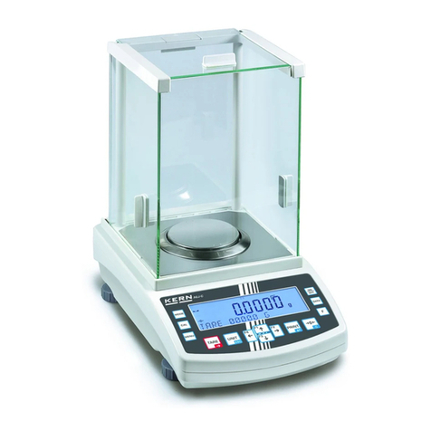
KERN 770-12 User manual

68
770/GS/GJ-BA-defsi-0023
E KERN 770/GS/GJ
Version 2.3 04/2000
Operating Instructions
Electronic Precision Balance
Contents
1OPERATING ELEMENTS 69
1.1 IMPORTANT INSTRUCTIONS 75
1.2 GETTING STARTED 76
1.2.1 Installation of the weighing chamber 76
1.2.2 Connecting the Balance to AC Power 78
1.2.3 Safety Precautions 79
1.2.4 Connecting Electronic Peripheral Devices 79
1.2.5 Levelling the Balance Using the Level Indicator 79
1.3 OPERATING THE BALANCE 80
1.3.1 Warm-up Time 80
1.3.2 Turning the Balance On and Off (Standby Mode) 80
1.3.3 Self-Test 80
1.3.4 Taring 81
1.3.5 Simple Weighing (Weight Determination) 81
1.4 ADJUSTING (FORMERLY CALIBRATION) 82
1.4.1 Internal Adjusting for Balances with a Built-in Adjusting Weight 82
1.4.2 External Adjusting 83
1.4.3 Blocking the Adjusting Functions 83
1.5 DATA INTERFACE 84
1.6 BELOW BALANCE WEIGHING 85
1.7 ANTI-THEFT LOCKING DEVICE 85
1.8 TROUBLESHOOTING GUIDE 86
1.9 CARE AND MAINTENANCE 87
1.9.1 Cleaning 87
1.9.2 Safety Inspection 87
2DECLARATIONS OF CONFORMITY 88
3BALANCE OPERATING MENU 90
3.1 CHANGING MENU CODE SETTINGS 90
3.1.1 Accessing the Menu 91
3.1.2 Reset Function - Undoing All Menu Code Changes 92
3.2 BALANCE OPERATING PARAMETERS 93
3.2.1 Adapting the Balance to Ambient Conditions 93
3.2.2 Standard Weighing Mode - Manual Filling Mode 93
3.2.3 Stability Range 93
3.2.4 Tare Parameter 94
3.2.5 Auto Zero Function 94
3.2.6 Adjusting and Linearisation Functions Using CAL 94
3.3 UNIT CONVERSION 95
3.3.1 Weight Units 95
3.4 INTERFACE PARAMETER SETTINGS 96
3.4.1 Baud Rate 96
3.4.2 Parity 96
3.4.3 Number of Stop Bits 96
3.4.4 Handshake Mode 96
3.5 DATA INTERFACE 97

770/GS/GJ-BA-defsi-0023 69
3.5.1 Data Output Parameter 97
3.5.2 Auto Print 97
3.5.3 Data Output at Defined Intervals 98
3.5.4 Automatic Taring after Data Output 98
3.5.5 Data ID Codes 99
3.5.6 Automatic Output of the Tare Memory Data 99
3.6 ADDITIONAL FUNCTIONS 99
4APPLICATION PROGRAMS 100
4.1 TARE MEMORY 100
4.2 PRACTICAL EXAMPLE “NET TOTAL“ 101
4.3 WEIGHING IN PERCENT 102
4.4 PRACTICAL EXAMPLE “DETERMINATION OF THE RESIDUAL WEIGHT IN PERCENT“ 103
4.5 COUNTING 104
4.6 PRACTICAL EXAMPLE “COUNTING SMALL PARTS“ 105
4.7 ANIMAL WEIGHING/AVERAGING 106
4.8 PRACTICAL EXAMPLE “ANIMAL WEIGHING IN THE AUTOMATIC START MODE“ 108
4.9 PRACTICAL EXAMPLE “ANIMAL WEIGHING IN THE MANUAL START MODE“ 109
5ISO/GLP-COMPLIANT PRINTOUT OR RECORD 110
5.1 DATA PRINTOUT/RECORD (ISO/GLP-COMPLIANT) 112
5.2 DATA PRINTOUT/RECORD FOR APPLICATION PROGRAMS (E.G. COUNTING) 113
6INTERFACE DESCRIPTION 114
6.1 GENERAL INFORMATION 114
6.2 INTERFACING DEVICES WITH THE BALANCE 114
6.3 GENERAL SPECIFICATIONS 115
6.4 DATA OUTPUT FORMATS 116
6.5 DATA INPUT FORMATS 120
6.6 SYNCHRONISATION AND DATA OUTPUT PARAMETERS 123
6.7 INTERFACE PARAMETER SETTINGS 126
6.8 PIN ASSIGNMENT CHART 127
7SPECIFICATIONS 129
8SUPPLEMENT - OVERVIEW OF ALL MENU SETTINGS 132
Please read through these installation and operating instructions carefully before
operating your new balance.
After unpacking the balance, please check it immediately for any visible damage as a
result of rough handling during shipment.
If this is the case, proceed as directed in the section entitled "Safety Inspection."
Save the box and all parts of the packaging for any future shipment of your balance.
Before packing your balance, unplug all connected cables to prevent damage.
1 Operating Elements
70
770/GS/GJ-BA-defsi-0023
KERN 770-12, KERN 770-13, KERN 770-14, KERN 770-15
No. Designation No. Designation
1 Weighing pan 13 Verification ID label with metrological data
2 Shield ring for verified balances approved for use as
3 Metrological ID label for verified balances legal measuring instruments
approved for use as legal measuring 14 AC jack
instruments 15 Manufacturer’s label with the CE mark of
4 Menu access switch conformity
5 Levelling foot 16 Data interface port
6 TARE key 17 Level indicator
7 PRINT key (data output)
8 Function key F
9 CAL key
10 CF key (clear function) Not shown:
11 ON/OFF key Dust cover
12 Weight display Caps and plugs (set)
KERN 770-60

770/GS/GJ-BA-defsi-0023 71
No. Designation No. Designation
1 Weighing pan 12 Weight display
2 Shield disk 13 AC jack
3 Metrological ID label for verified balances 14 Verification ID label with metrological data
approved for use as legal measuring for verified balances approved for use as
instruments legal measuring instruments
4 Access switch 15 Manufacturer’s ID label with the
5 Levelling foot CE
CECE
CE mark of conformity
6 TARE key 16 Data interface port
7 PRINT key (data output) 17 Level indicator
8 CF key (clear function)
9 Function key F
10 CAL key
11 ON/OFF key

72
770/GS/GJ-BA-defsi-0023
KERN GS / KERN GJ
Pos. Designation Pos. Designation
1 Weighing pan 14 Level indicator
3 Shield ring 15 AC jack
4 Levelling foot 16 Menu access switch
5 Level indicator 17 Data interface port
6 PRINT key (data output) 18 Draft shield cover
7 CF key (clear function) 19 Glass draft shield cylinder
8 Function key F20 Pan support
9 CAL key
10 ON/OFF key
11 Weight display
12 Manufacturer’s ID label with the
CE
CECE
CE mark of conformity
13 Lug for attaching an anti-theft locking Not shown:
device Caps and plugs (set)

770/GS/GJ-BA-defsi-0023 73
KERN GS / KERN GJ
Pos. Designation Pos. Designation
1 Weighing pan 12
Manufacturer’s ID label with the CE
CECE
CE mark
3 Shield ring of conformity
4 Levelling foot 13 Lug for attaching an anti-theft locking
5 TARE keys device
6 PRINT key (data output) 14 Level indicator
7 CF key (clear function) 15 AC jack
8 Function key F16 Menu access switch
9 CAL key 17 Data interface port
10 ON/OFF key 20 Pan support
11 Weight display
Not shown:
Caps and plugs (set)

74
770/GS/GJ-BA-defsi-0023
KERN GS / KERN GJ
Pos. Designation Pos. Designation
1 Weighing pan 12
Manufacturer’s ID label with the CE
CECE
CE mark
4 Levelling foot of conformity
5 TARE key 13 Lug for attaching an anti-theft locking
6 PRINT key (data output) device
7 CF key (clear function) 14 Level indicator
8 Function key F15 AC jack
9 CAL key 16 Menu access switch
10 ON/OFF key 17 Data interface port
11 Weight display 21 Shock absorber
Not shown
Caps and plugs (set)

770/GS/GJ-BA-defsi-0023 75
1.1 Important Instructions
Ambient Conditions
The KERN 770, GS and GJ balances are designed to
provide reliable weighing results under normal ambient
conditions in the laboratory and in industry. When choosing
a location to set up your balance, observe the following so
that you will be able to work with added speed and
accuracy:
- Set up the balance on a stable, even surface (benchtop
or floor);
- Avoid placing the balance in close proximity to a heater
or otherwise exposing the balance to extreme heat or to
direct sunlight;
- Protect the balance from drafts that come from open
windows and doors;
- Avoid exposing the balance to extreme vibrations during
weighing;
- Protect the balance from aggressive chemical vapours;
- Do not operate the balance in a hazardous
area/location.
Do not expose the balance to extreme moisture over long
periods. Moisture in the air can condense on the surface of
a cold balance whenever it is brought to a substantially
warmer place. If you transfer the balance to a warmer area,
make sure to condition it for about 2 hours at room
temperature, leaving it unplugged from AC power.
Afterwards, if you keep the balance connected to AC power,
the continuous positive difference in temperature between
the inside of the balance and the outside will practically rule
out the effects of moisture condensation.
Do avoid electric and magnetic fields around the balance.
Do check the balance with test weights at least once a day.
Balance’s opening causes invalidity of warranty !

76
770/GS/GJ-BA-defsi-0023
1.2 Getting started
Remove the plastic sheeting, adhesive tapes and foam material from the balance.
Important information:
Control Seals on Verified Balances Approved for Use as Legal Measuring
Instruments in the EU*:
Legal regulations require the verified balance to be sealed. This control seal consists
of an adhesive label with the name „KERN“ on it. This seal will be irreparably
damaged if you attempt to remove it. In this case, the validity of the seal becomes
void and you must have your balance re-verified.
For model 770-60
Connecting the Balance to the Electronics Box.
- Plug the cable into the socket of the electronics box
1.2.1 Installation of the weighing chamber
For models 770
Place the components listed below inside the chamber in
the order given:
- Shield ring
- Weighing pan
For models GS/GJ with a glass draft shield
- Place the shield disk on the balance. Turn the disk
counter-clockwise until it stops and is secured.
Place the components listed below on the balance in the
order given:
- Pan support
- Weighing pan
- Glass draft shield cylinder
- Draft shield cover

770/GS/GJ-BA-defsi-0023 77
For models GS/GJ with a rectangular weighing pan
- Place the weighing pan on the balance
For models GS/GJ with a round weighing pan
Place the shield disk on the balance. Turn the disk
counter-clockwise until it stops and is secured.
Place the components listed below on the balance in the
order given:
- Pan support
- Weighing pan

78
770/GS/GJ-BA-defsi-0023
1.2.2 Connecting the Balance to AC Power
The balance is powered by an AC adapter. Make sure that
the voltage rating printed on this unit is identical to your
local line voltage.
Important Note !
Use only original AC adapters by KERN. Use of AC
adapters from other manufacturers, even if these units have
a registered approval rating from a national testing
laboratory, requires the consent of a certified technician.
Build up power connection to the balance.
Plug the AC adapter into the line voltage.
For Adjusting of balance, see part 1.4 “Adjusting“

770/GS/GJ-BA-defsi-0023 79
1.2.3 Safety Precautions
The AC adapter rated to class 2 can be plugged into any
wall outlet without requiring any additional safety
precautions. The pole of the output voltage is connected to
the balance housing, which can be grounded for operation.
The data interface is also electrically connected to the
balance housing (ground).
1.2.4 Connecting Electronic Peripheral Devices
Make absolutely sure to unplug the balance from AC power
before you connect or disconnect a peripheral device
(printer of PC) to or from the interface port.
1.2.5 Levelling the Balance Using the Level Indicator
At the place of installation, level the balance using the
levelling feet so that the air bubble is centred within the
circle of the level indicator.

80
770/GS/GJ-BA-defsi-0023
1.3 Operating the Balance
1.3.1 Warm-up Time
To deliver exact results, the balance must warm up for at
least 30 minutes after initial connection to AC power or after
a relatively long power outage. Only after this time will the
balance have reached the required operating temperature.
1.3.2 Turning the Balance On and Off (Standby Mode)
Press the ON/OFF key to turn the display on and off.
1.3.3 Self-Test
After the balance has been turned on, automatic self-test of
the balance’s electronic circuitry is performed. At the end of
the self-test, a zero readout is displayed. This means that
the balance is ready to operate.

770/GS/GJ-BA-defsi-0023 81
The display shows the following special codes for your
information:
O displayed in the upper right corner stands for OFF
The balance was disconnected from AC power
(balance reconnected to AC power or power outage longer
than 3 seconds)
O displayed in the lower left corner means standby
The display has been turned off by the ON/OFF key. The
balance is now in the ready-to-operate mode and does not
require warm-up.
means busy
Once you have turned on the balance, that symbol will be
displayed until you press a key. During operation, this
symbol indicates that the balance processor is still busy
processing a function and will not accept another command
to perform any other functions at this time.
1.3.4 Taring
A weight can be determined accurately only from a defined
zero point. Press the TARE key to zero the weight display.
You can tare within the entire weighing range of the
balance.
1.3.5 Simple Weighing (Weight Determination)
Place your sample on the weighing pan to determine the
weight. Read off the weight indicated on the display only
after the weight unit “g“ or a different unit selected appears
as the stability symbol.

82
770/GS/GJ-BA-defsi-0023
1.4 Adjusting (formerly Calibration)
During adjusting, the sensitivity of the balance is adjusted to
changes in the ambient conditions.
You must adjust your new balance at the place of
installation after each warm-up period and before the first
measurement. You must also readjust your balance each
time you set it up in a different area or when the ambient
conditions change (especially the temperature).
The balance offers you various adjusting functions. You can
select these functions by setting the appropriate menu
codes. For more information, refer to part 2 “Balance
Operating Menu“.
Each adjusting function can be interrupted by pressing the
CAL key .
1.4.1 Internal Adjusting for Balances with a Built-in
Adjusting Weight
Menu code selection: 1 9 3*
Alterations and settings can be taken from the menu item
“Balance Operating Menu“.
When the display shows a zero readout, press the CAL key
to activate the adjusting function.
If any interference affects the adjusting procedure, you may
obtain a brief display of the error code “Err 02“. In this case,
tare and press the CAL key once again.
Important Note !
During adjusting, the weighing pan must be unloaded.
* = factory setting for balances with a Built-in Adjusting
Weight

770/GS/GJ-BA-defsi-0023 83
1.4.2 External Adjusting
Menu code selection: 1 9 1*
The external adjusting weight is a standard fitting for KERN
balances without a built-in Adjusting Weight. This adjusting
weight allows the checking and new adjustment of your
balance at any time.
When a zero readout is displayed, press the CAL key . This
starts adjusting. The adjusting weight in grams is then
displayed.
Errors or interference at the start of the adjusting routine are
indicated by the error code “Err 02“. If this is the case, tare
and press the CAL key again when a zero readout appears.
Centre the adjusting weight on the weighing pan. The
balance then adjusts automatically. At the end of adjusting,
the adjusting weight readout and the stability symbol “g“ are
displayed.
1.4.3 Blocking the Adjusting Functions
The adjusting functions can be blocked by menu code
setting 1 9 7.
* = factory setting for balances with built-in Adjusting Weight

84
770/GS/GJ-BA-defsi-0023
1.5 Data Interface
The Data interface port is situated below the protective cap
at the back of the balance.
Unfasten the protective cap from the data interface port.
Important Note !
Make absolutely sure to unplug the balance from AC power
before you connect or disconnect a peripheral device
(printer or PC) to or from the interface port.
To print or output data, press the PRINT key.
For information about the data output parameters and data
ID codes, see from page 87.
For closer details on the data interface (such as the data
output or input formats, pin assignment, etc), see part 5,
“Interface Description“.

770/GS/GJ-BA-defsi-0023 85
1.6 Below Balance Weighing
A port for a below-balance weighing hanger is located on
the bottom of the balance
To open the below-balance port, remove the cover plate
from the bottom of the balance.
To hook a sample on the hanger, open the below-balance
port by removing the cover plate.
Important Note !
When you use below-balance weighing hangers, you must
install a shield for protection against drafts.
1.7 Anti-theft Locking Device
To fasten an anti-theft locking device, use the lug located on
the rear panel of the balance.

86
770/GS/GJ-BA-defsi-0023
1.8 Troubleshooting Guide
Problem
Possible Causes Solution
No segments appear on the
weight display
- No AC power available
- The AC adapter is not
plugged in
- Check the AC power
supply
- Plug in the AC adapter
The weight display shows “H“ - The load exceeds the
capacity of the balance
- Unload the balance
The weight display shows “L“
or “Err 54“
- The weighing pan and/or
the pan support disk is/are
not in place
- Position the pan and/or the
pan support disk
(depending on the balance
model)
The weight display briefly
shows “Err 02“
- The display did not show a
zero readout when the
CAL key was pressed to
adjust
- The balance is loaded
- Press the TARE key ; then
press the CAL key once
again
- Unload the balance
The special code remains
displayed
- None of the keys has been
pressed since the balance
was turned on
- Press a key
The weight readout changes
constantly
- Unstable ambient
conditions
- Too much vibration or the
balance is exposed to a
draft
- Set up the balance in
another area
- Access the menu to select
the correct code for the
weighing environment
- The draft shield is not
completely closed
- Close the draft shield
- A foreign object is caught
between the pan and the
balance housing
- Remove the foreign object
- The below-balance
weighing port is open
- Close the port
- The sample does not have
a stable weight (absorbs
moisture or evaporates)
- The sample is electrostati
cally charged
The weight readout is
obviously wrong
- The balance has not been
adjusted
- The balance was not tared
before weighing
- The air bubble of the level
indicator is not within the
circle
- Adjust the balance
- Tare before weighing
- - Level the balance

770/GS/GJ-BA-defsi-0023 87
1.9 Care and Maintenance
1.9.1 Cleaning
Before cleaning the balance, unplug the AC adapter from
the wall outlet.
Please do not use any aggressive cleaning agents (solvents
or similar agents). Instead, use a piece of cloth which has
been wet with a mild detergent (soap). Make sure that no
liquid enters the balance housing. After cleaning, wipe down
the balance with a soft, dry piece of cloth.
Carefully remove any sample residue/spilled powder by
using a brush or a hand-held vacuum cleaner.
1.9.2 Safety Inspection
If there is any indication that safe operation of the balance
with the AC adapter is no longer guaranteed, turn off the
power and disconnect the equipment in a secure place to
ensure that it cannot be used for the time being.
Safe operation of the balance with the AC adapter is no
longer ensured when
- there is visible damage to the AC adapter;
- the AC adapter no longer functions properly;
- the AC adapter has been stored for a relatively long
period under unfavourable conditions.
In this case, notify your nearest supplier. Only service
technicians who have access to the required maintenance
manuals are allowed to perform maintenance and
repairwork on the equipment.
The electrical and electronic components used in the
balance are rated to at least Class KSF according to DIN
40040.
This manual suits for next models
16
Table of contents
Other KERN Scale manuals

KERN
KERN VHB User manual

KERN
KERN PCB Series User manual

KERN
KERN KIP-V20 User manual

KERN
KERN PLS Series User manual

KERN
KERN WTB-BA-e-1214 User manual

KERN
KERN KERN FWN User manual

KERN
KERN EOC 6K-3 User manual

KERN
KERN MBC-M Series User manual

KERN
KERN ILT series User manual

KERN
KERN RXB 30K10M User manual