4
Assemble units as described herein only. To do otherwise
may result in instability. All screws, nuts and bolts must be
tightened securely and must be checked periodically after
assembly. Failure to assemble properly, or to secure parts
may result in assembly failure and personal injury.
Pirouette Tables™ Nesting-Base with Villa, PowerUp or No Power - Velcro®Wire Managers & Villa Power Module
Assembly Instructions
Pirouette Table with Villa
Power Module with 3-Prong
Plug
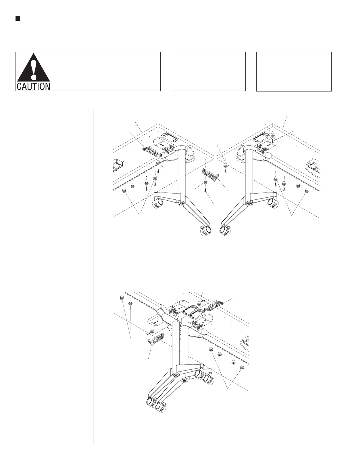
Note: If tables are configured
table-to-table or back-to-back, tables
must be mechanically connected with
gangers or splice plates.
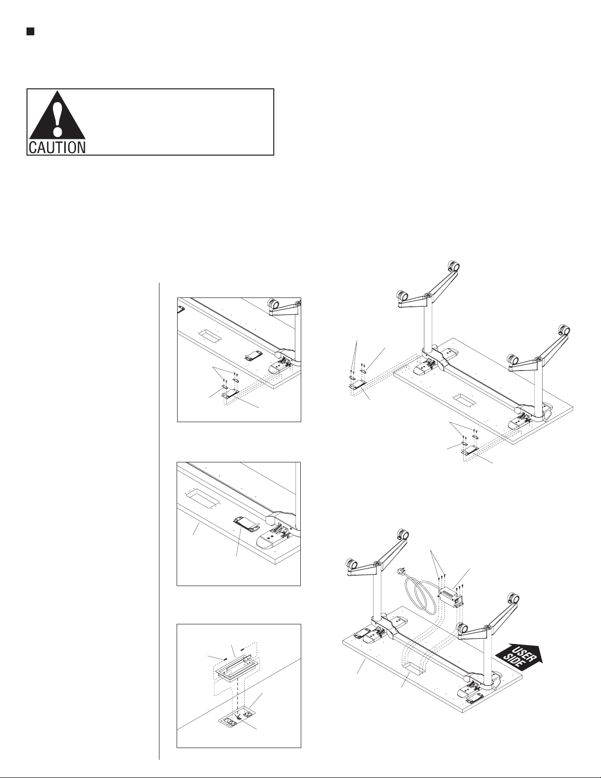
1. Position the Villa power module with
3-prong plug on the underside of the
tabletop above the cutout. Orient the
notch in the module to face the user
side (Figure 7).
2. Align the six mounting holes on the
power module with the six pre-drilled
holes in the tabletop, then secure
the bracket to the underside of the
tabletop with the six #8 x 3/4” screws
provided (Figure 7).
Pirouette Table with Villa
Power Module Grommet
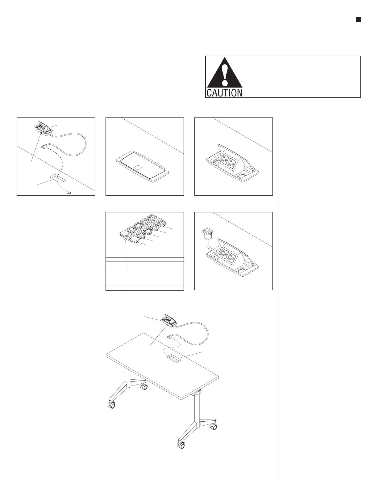
1. Position the Villa power module
grommet above the tabletop cutout
with the lid opening towards the user
(Detail E).
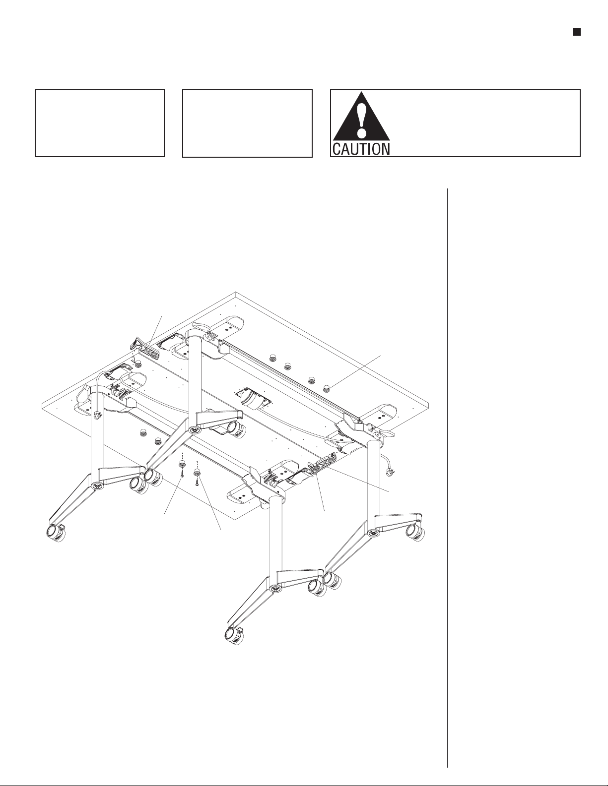
Velcro®Wire Managers
Installation
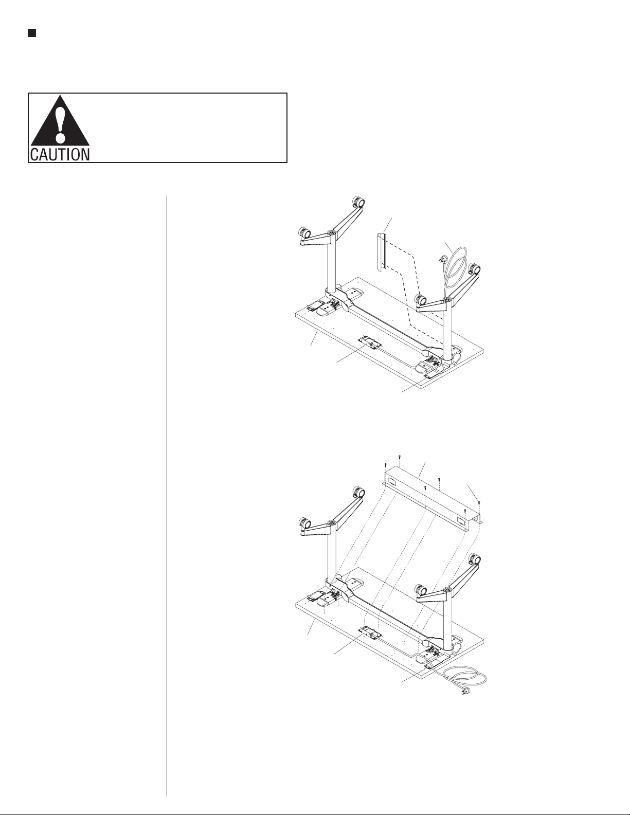
Note: If optional wire trough is to be
installed on table length of 60”-72”,
only install two Velcro wire managers
closest to the side edges of the
tabletop (Detail C).
1. Position the two Velcro®wire
managers (Figure 6), four if table
length is 60”-72”, unless wire trough
is to be installed (Detail C), over the
pre-drilled holes in the underside of
the tabletop where illustrated. Locate
and place two steel position tabs,
one at each end over the mounting
holes in the wire manager, then
secure using four #10 x 5/8” screws,
through the two position tabs, wire
manager mounting holes and into
the tabletop. Do not over-tighten
(Figure 6).
Note: Velcro®wire managers must
be rotated 90 to mount onto the
underside of any 18” depth tabletop
(Detail D).
#10 x /”
5
8
screws
Velcro®
wire manager
steel
position tab
/”
5
8
screws steel
position
tab
Velcro®
wire manager
6
7
tabletop
cutout
tabletop
Villa power
module with
3-prong plug
#8 x /”
3
4
screws
Villa power module
grommet
#6 x /”
1
2
screw
tabletop
cutout
tabletop
Villa power
module with
3-prong plug
Velcro®
wire manager
tabletop
elco Wire Manager
tabletop only)
#10 x /”
5
8
screws
Velcro®
wire manager
steel
position
tab
elco Wire Manager
tabletop only)
2. Push the grommet into the cutout,
tap lightly with a rubber mallet
if required, use caution to avoid
scratching the grommet (Detail E).
3. Secure the grommet to the tabletop
by inserting two #6 x 1/2” screws
through the holes on the inside of the
module into the cut edge of the top
(Detail E).