2
Assemble units as described herein only. To do otherwise
may result in instability. All screws, nuts and bolts must be
tightened securely and must be checked periodically after
assembly. Failure to assemble properly, or to secure parts
may result in assembly failure and personal injury.
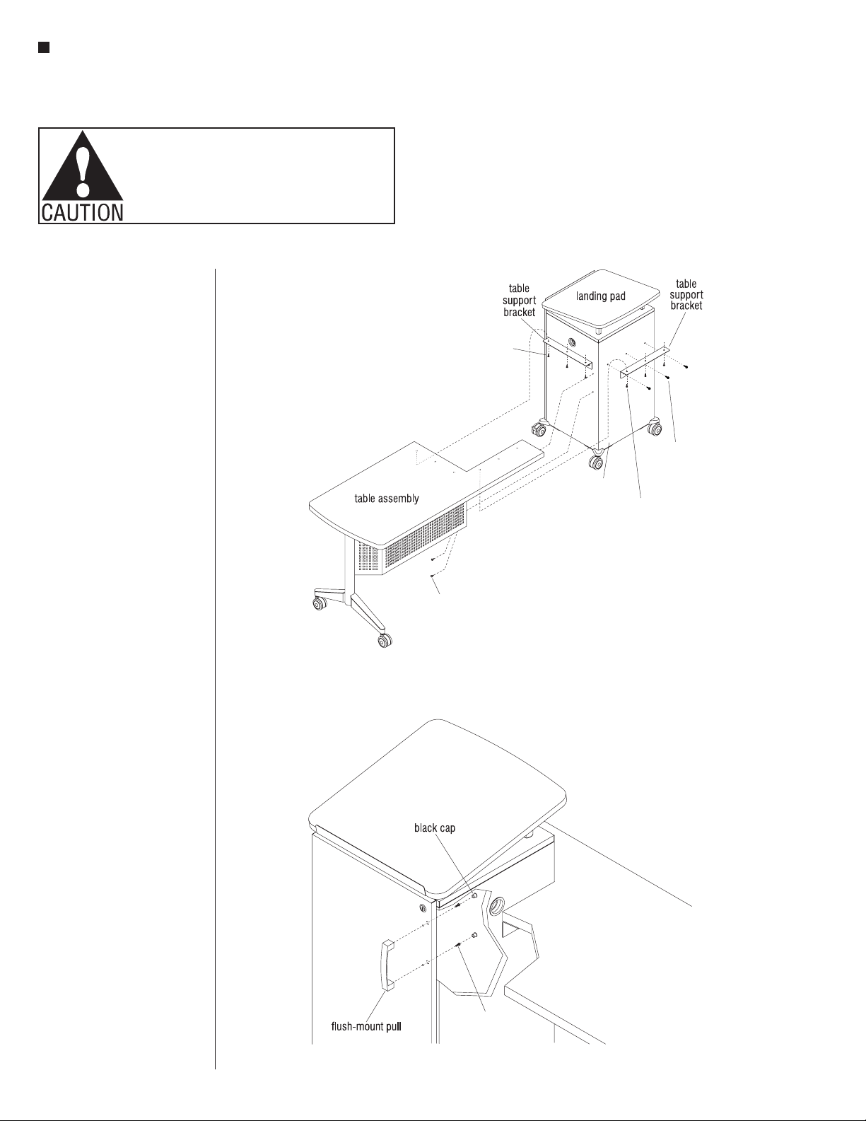
Instruct®Classroom Furniture - All Terrain®Mobile Instructor’s Desk
Assembly Instructions
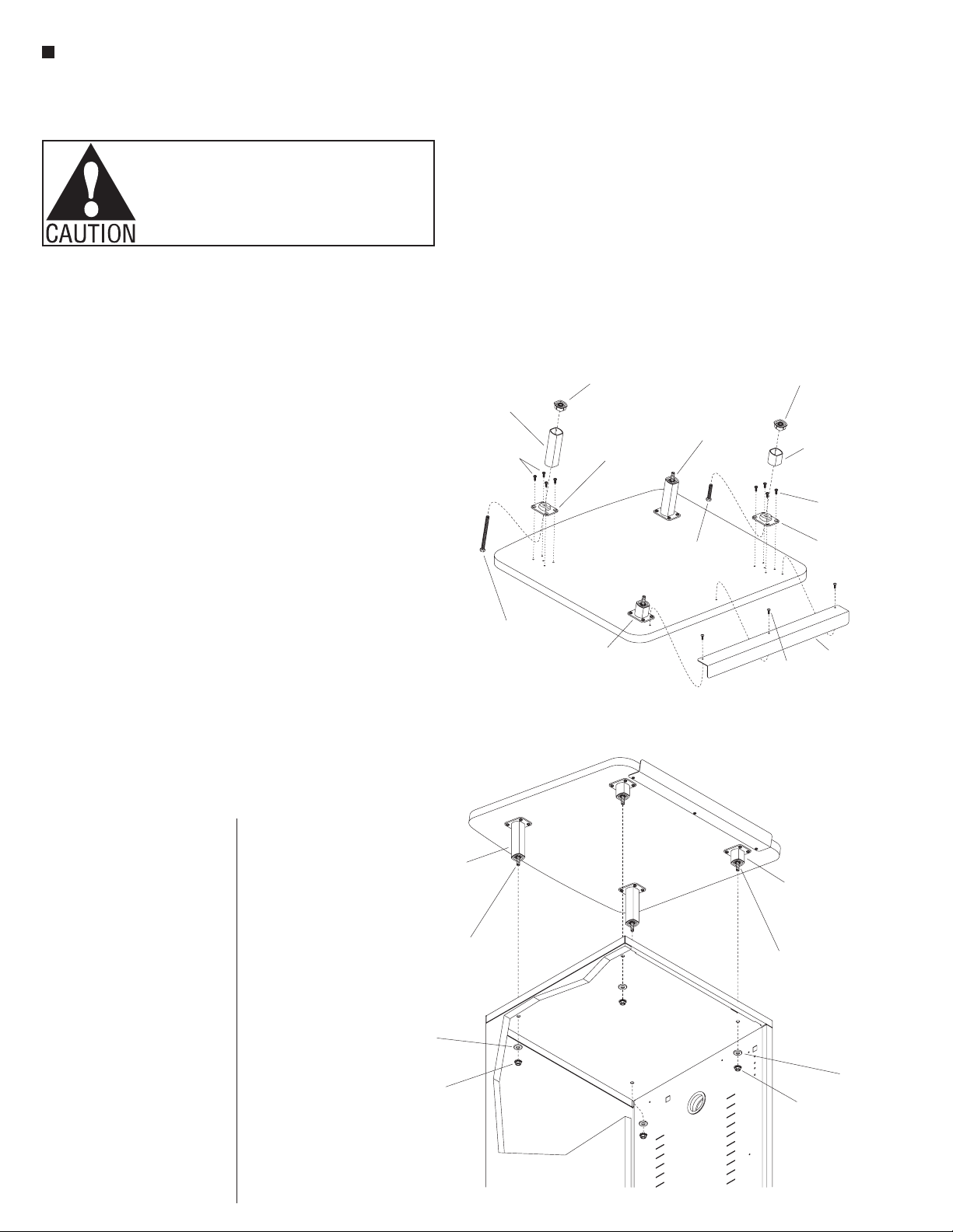
tall and two short) as illustrated.
Position the shorter landing pad
post/bushings to the installed
upper bushings closest to the
installed document ledge. Take
care to orient the angled edge
of the posts correctly to match
the slope of the landing pad
underside (Figure 3).
6. Repeat the above procedure with
the longer landing pad posts,
positioning them to the rear upper
bushings at the 4” bolt locations,
correctly matching the slope angle
(Figure 3).
7. Orient the landing pad to be
right-side up and with the
document ledge to the user side
of the storage tower as illustrated.
Carefully position the landing pad
post assemblies with installed
bushings, posts & bolts such that
the four bolts insert down through
the four mounting holes in the top
of the tower (Figure 4).
8. From inside the tower, locate the
1/4-20 bolts inserted through the
top and place a 1/4” washer and a
1/4-20 nut onto each bolt. Tighten
nuts to secure the landing pad to
the tower top (Figure 4).
Sloped Landing Pad Assembly
1. Carefully place the slopped
landing pad upside down on a
soft, protective surface. Open the
hardware pack and familiarize
yourself with all parts and
hardware. Take special note of the
two different sized landing pad
posts and the two different sized
attachment bolts (Figure 3).
Note: The shorter landing
pad posts and bolts are to
be installed to the front,
user side of the storage
tower. The user side has the
document ledge attached
to it.
2. Orient the user side of the landing
pad to be over the edge of a table
(or the storage tower top) for
ease of installation, then align the
mounting holes of the document
ledge with the pre-drilled
mounting holes on the underside
of the landing pad. Secure the
ledge to the front, user side of the
pad using three #8 x 1/2” truss
head screws (Figure 3).
3. Insert two 1/4-20 x 4” bolts and
two 1/4-20 x 11/2” bolts into the
four upper landing pad bushings
as illustrated (Figure 3).
4. Secure the upper bushings with
the shorter 11/2” long bolts to the
underside of the landing pad near
the document ledge using four
#8 x 1/2” screws each. Then secure
the two upper bushings having
the 4” long bolts to the underside
of the landing pad using four
#8 x 1/2” screws each (Figure 3).
Note: The top of all four
landing pad posts are angled
to correspond with the slope
of the landing pad when
installed on the storage
tower.
5. Place the lower post bushings
down onto the flat, bottom sides
of the landing pad posts (two
document
ledge
#8 x /”
1
2
landing pad
(upper)
11
/ -20 x 1 /”
42
bolt
landing pad
post (shorter,
instructor-side)
l postower
bushing
landing pad
(underside)
landing pad
,
back-side)
1/ -20 x 4
4”
bolt
landing pad
post assembly
(longer, back-side)
#8 x /”
1
2
screws
landing pad
mount bushing
(upper)
#8 x /”
1
2
screw
lower post
bushing
landing pad
post assembly
(shorter, instructor-side)
landing pad
(underside)
landing pad
post assembly
, back-side)
1/”at
4
washer
1/ -20”
4
nut
1/”at
4
washer
1/ -20”
4
nut
1/4-20 x 4”
bolt
storage
tower
landing pad
post assembly
(shorter, instructor-side)
1/42
-20 x 1 /”
1
bolt