3
Assemble units as described herein only. To do otherwise
may result in instability. All screws, nuts and bolts must be
tightened securely and must be checked periodically after
assembly. Failure to assemble properly, or to secure parts
may result in assembly failure and personal injury.
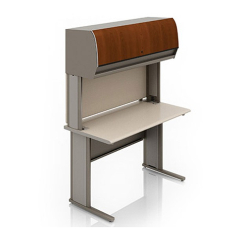
Likha Casegoods - Adjustable-Height Units
Assembly Instructions
Adjustable-Height Worksurface
Installation
1. Carefully position the worksurface
on top of two adjustable-height
leg assemblies. One side of the
worksurface at a time, align two
mounting holes on each L-bracket
with the four pre-drilled holes in
the worksurface, referencing the
correct illustration that matches your
configuration for correct mounting
hole locations (Figures 3, 4 & 5).
Secure each L-bracket to the
worksurface using two #10 x 7/8”
Phillips pan head screws per bracket
at each side of the table
(Figures 3, 4 & 5).
worksurface
bookcase/cabinet/
credenza leg
assembly
L-bracket
#10 x /”
7
8
T-support
bracket
Figure 3 - Adjustable-Height Bookcase
Leg
- Adjustable-Height Cabinet Leg
- Adjustable-Height Credenza Leg
adjustable-height
worksurface
panel leg
T-leg assembly
L-bracket
#10 x /”
7
8
Phillips pan
head screw
T-support
bracket
Figure 4 - Adjustable-Height Panel Leg
- Adjustable-Height T-Leg
Figure - Adjustable-Height Panel Leg with Sleeve5
adjustable-height
worksurface
panel leg with sleeve
L-bracket
#10 x /”
7
8
Phillips pan
head screw
T-support
bracket
Table Wiring Installation
1. Position the control box underneath
the worksurface in the desired
installation location. Transfer and
mark the Velcro hook strip locations
pre-installed on the control box to
the worksurface. Remove the backing
from the individual peel & stick
Velcro loop strips to expose the
adhesive surfaces. Position the loop
strips in the marked locations. Apply
firm pressure to set the adhesive.
Press the Velcro hook strips against
the loop strips to secure the control
box underneath the worksurface.
Note: When plugging leg control
cord ends in, make sure to push in
straight to avoid bending any pins
in the electrical control box or leg
motor.
Note: If any plug needs to be
removed, make sure the power cord
is un-plugged from the power source
outlet first. Then push down on the
release tab on the control cable plug
while simultaneously pulling on the
end to remove from the socket.
2. Plug the leg control cord into one of
the two rectangular sockets on the
control box, then route cord to the
leg. Plug other end of the cord into
the open socket on the leg motor.
Repeat this process to install the
second leg control cord into the
opposite leg motor.
3. Underneath the worksurface on
the user side, position the key pad
in the desired location and secure
using two #8 x 5/8” screws. Do not
overtighten screws. Once key pad
is mounted, route attached cord to
the control box and plug into the
appropriate socket.
4. Five cord strain relief clips are
included to keep cords tight to the
table, but it is not necessary to use
all five. Insert the cable into the
opening of the clip, then secure the
clip to the underside of the table
using one #8 x 5/8” screw. Repeat this
step to install any remaining cord
strain relief clips.
5. The final cord to be installed is the
power cord. Plug power cord into
remaining open socket on the control
box. Route the power cord to an
approved power source.
6. Raise the adjustable-height
worksurface to the maximum height
using the key pad, allowing easier
access to the remaining bracket
mounting hole.
7. Using the L- and T-support bracket’s
remaining mounting holes as
templates (four per L-bracket and
four for the T-Support bracket on
each side of the worksurface), secure
the worksurface to the brackets using
#10 x 7/8” Phillips pan head screws
(Figures 3, 4 & 5).
8. If an adjustable-height bookcase,
cabinet or credenza leg was
assembled to the worksurface
and requires an optional wire
management sleeve, proceed to
“Adjustable-Height Bookcase,
Cabinet & Credenza Leg - Wire
Management Sleeve Assembly”
instructions on page 4. If a
adjustable-height panel leg with
sleeve was assembled to the
worksurface, proceed to
“Adjustable-Height Panel Leg with
Sleeve - Wire Management Sleeve
Assembly” instructions on page 5.
