manuals.online logo
Brands
  1. Home
  2. •
  3. Brands
  4. •
  5. KI
  6. •
  7. Indoor Furnishing
  8. •
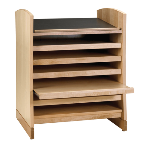
  9. KI Tattoo Low Cupboard User manual

KI Tattoo Low Cupboard User manual

Assemble units as described herein only. To do otherwise
may result in instability. All screws, nuts and bolts must be
tightened securely and must be checked periodically after
assembly. Failure to assemble properly, or to secure parts
may result in assembly failure and personal injury.
Assembly Instructions
Tattoo™ Low Cupboard
August 2019
Figure
1
15
/ -20 x /”
machine
screws
48
leg post
(caster)
leg post
(caster)
stem-mount
caster (locking)
stem-mount
caster
(non-locking)
storage unit
(low cupboard
shown)
power drill
driver with 8”
drill extension and
#3 Phillips bit
Detail A
stem-mount
caster
leg post
(caster)
storage unit
(low cupboard
shown)
Required Tools
• 12 mm Hex Wrench
• #2 Phillips Screwdriver
• Power Drill Driver
• #3 Phillips Tip
• 8” Drill Extension
• 7/16” Hex Wrench (raised
worktop only)
Note: Leg posts are designed to
receive either casters or glides,
based on their overall length. Leg
posts at 57/16” long are designed for
casters, while 63/4” long leg posts
are for glides. If your installation
contains a mix of units with casters
and units with glides, take care to
not mix up the leg components, or
disassembly and re-assembly will be
required to correct the unit heights.
Leg Installation
1. Carefully lay the low cupboard onto
a soft, protective surface on it’s
back-side. Caution: The assistance
of a second person may be required
to turn the unit onto its back
(Figure 1).
2. Align the mounting holes of each
leg post with the mounting holes on
the underside of the low cupboard.
Using a power drill driver with 8”
drill extension and #3 Phillips bit,
secure each leg post to the low
cupboard using three 1/4-20 x 5/8”
machine screws. Take care to not
scratch the legs with the drill when
assembling the legs (Figure 1).
3. If the low cupboard being assembled
is a caster leg unit, go to “Caster
Installation” instructions on this
page. If low cupboard has adjustable
glide legs, go to “Glide Installation”
instructions on the next page.
Caster Installation
1. Thread the stem of each stem-mount
caster into the threaded insert at the
underside of each leg post, making
sure to position the two locking
casters toward the front, user side of
the low cupboard and the
non-locking casters at the back.
Tighten the casters to the underside
of the low cupboard using a 12 mm
hex wrench (Figure 1 & Detail A).
2. Once all casters have been installed
to the caster leg posts, carefully
turn the unit to the upright position.
Caution: The assistance of a second
person may be required to turn the
unit upright.
2
Assemble units as described herein only. To do otherwise
may result in instability. All screws, nuts and bolts must be
tightened securely and must be checked periodically after
assembly. Failure to assemble properly, or to secure parts
may result in assembly failure and personal injury.
Tattoo™Storage - Low Cupboard
Assembly Instructions
Figure
2
leg post
(glide)
stem-mount
glide
stem-mount
glide
storage unit
(low cupboard
shown)
stem-mount
glide
leg post
(glide)
Detail B
storage unit
(low cupboard
shown)
Glide Installation
1. Thread the stem of each glide into
the threaded insert at the underside
of each leg post. Twist the glides in
clock-wise, fully to the bottom of
the leg post. This will allow level
adjustment of the low cupboard if
required when placed in its final
location (Figure 2 & Detail B).
2. Once all glides have been installed
to the underside of the low cupboard
leg posts, carefully turn the cupboard
to the upright position. Caution:
The assistance of a second person is
required to turn low cupboard units
to the upright position.
3. Place the low cupboard in its final
location. To raise a leg of the unit for
leveling, rotate a glide out as needed.
To lower a low cupboard leg after it
has been raised, turn the glide back
into the leg as needed. Only adjust
the glides as needed to make the low
cupboard level.
4. If a padded topper is to be installed
on the low cupboard, go now
to “Padded Topper Installation”
instructions on page 6. If a
raised-worktop is to be installed
on the low cupboard, go now to
“Low Cupboard, Raised-Worktop
Installation” instructions on the next
page.
3
Assemble units as described herein only. To do otherwise
may result in instability. All screws, nuts and bolts must be
tightened securely and must be checked periodically after
assembly. Failure to assemble properly, or to secure parts
may result in assembly failure and personal injury.
Tattoo™Storage - Low Cupboard with Raised Worktop
Assembly Instructions
Low Cupboard, Raised-Worktop
Installation
1. Carefully turn the worktop upside
down onto a soft, protective surface
(Figure 3).
2. Take a post bolt and post flange in
hand, then press the threaded end of
the post bolt through the recessed
hex of the flange. Repeat this process
for the remaining four bolts to four
flanges (Figure 3 & Detail C).
3. At the underside of the worktop,
locate the five sets of five pre-drilled
holes, one set near each corner and
one set in the center of the worktop.
Position a post flange with post bolt
aligned over one set of pre-drilled
holes as illustrated. Using a hand
screwdriver with #2 Phillips tip,
secure the post flange to the
worktop using four #8 x 1/2” wood
screws. Take care to not secure too
tight. Repeat this step to install the
remaining flanges with bolts to the
worktop (Figure 3 & Detail C).
4. Locate five posts and five bottom
caps. Press a bottom cap onto
one end of each post, then press
a post with cap onto each of the
five installed post flanges, so the
threaded end of the bolts protrude
through the bottom caps (Figure 3 &
Detail C).
Note: Low cupboard cabinets with
raised-worktop which are to receive
a universal-height adjustable screen,
use a specific back-overhanging
worktop which must be oriented with
the overhang to the rear, non-user
side of the cabinet.
Caution: Take extra care when
turning the worktop with post
assemblies right-side up onto the
cabinet. Scraping or sliding the
post assembly bolts will scratch the
painted top of the cupboard. Two
people may be required to turn the
worktop over and align bolts of post
assemblies carefully through the
mounting holes in the low cupboard
top.
5. Assure that all bottom caps to
posts, and posts to post flanges are
press-fit together. If the parts do not
stay pressed together, five hands
or more may be required to flip the
raised-worktop with post assemblies
over safely. If worktop is to have a
universal-height adjustable screen
installed, assure that the over-hang
back-side of the raised worktop
is oriented to the back of the low
cupboard. Carefully turn the raised
worktop with post assemblies over,
aligning and inserting all five post
bolts carefully through the five
mounting holes in the low cupboard
top without scratching it (Figure 4).
6. Open the cupboard doors to gain
access to the post assembly bolts
at the underside of the top. Using
a flat washer and 1/4-20 hex nut as
illustrated at each of the five post
bolts, twist on then tighten all five
nuts with a 7/16” hex wrench (Figure 4
& Detail D).
bottom
cap
post
post
bolt
#8 x /”
oval head
wood screw
1
2
post
flange
Figure 3
worktop
universal-height
adjustable screen
mounting holes
post
mounting
holes
Detail C
bottom cap
post
post
bolt
post
flange
worktop
#8 x /”
oval head
wood screw
1
2
raised-worktop
Figure
4
low
cupboard
flat
washer
1/ -20
hex nut
4
post
assembly
Detail D
flat
washer
1/ -20
hex nut
4
post
bolt
raised-
worktop
low
cupboard
4
Assemble units as described herein only. To do otherwise
may result in instability. All screws, nuts and bolts must be
tightened securely and must be checked periodically after
assembly. Failure to assemble properly, or to secure parts
may result in assembly failure and personal injury.
Tattoo™Storage - Low Cupboard with Raised Worktop - Universal-Height Adjustable Screen
Assembly Instructions
Universal Height-Adjustable
Screen Installation
1. Locate an adjustable mechanism
and position the mounting bracket
to align with the pre-drilled holes
on the underside of the worktop.
Secure mechanism to the underside
of the worktop using four #12 x 3/4”
Phillips truss head screws (Figure 5
& Detail E).
2. Insert a square holed sleeve onto
the adjustable mechanism rod, then
place the longer connecting rod
onto the square holed sleeve just
installed (Detail F). Finally, insert a
second square holed sleeve onto the
opposite end of the connecting rod
and hold rod up, in position for
step 3 on the next page (Figure 6).
Figure 5
vertical
railway
adjustable
mechanism
#12 x /”
Phillips truss head
screws
3
4
mounting
bracket
raised-worktop
low
cupboard
Figure 6
connecting
rod
adjustable
mechanism
square
holed sleeve
square
holed sleeve
adjustable
mechanism
rod
Detail E
vertical
railway
adjustable
mechanism
mounting
bracket
#12 x /”
Phillips truss head
screws
3
4
Detail F
connecting
rod
square
holed
sleeve
adjustable
mechanism
rod
5
Assemble units as described herein only. To do otherwise
may result in instability. All screws, nuts and bolts must be
tightened securely and must be checked periodically after
assembly. Failure to assemble properly, or to secure parts
may result in assembly failure and personal injury.
Tattoo™Storage - Low Cupboard with Raised Worktop - Universal-Height Adjustable Screen
Assembly Instructions
Universal Height-Adjustable
Screen Installation (cont.)
3. Locate the opposite-side adjustable
mechanism and orient the mounting
bracket up to the underside of the
worksurface, then slide it over,
inserting the adjustable mechanism
rod into the square holed sleeve/
long connecting rod (installed in
step 2, page 5), synchronizing the
two mechanisms together. Secure
the mounting bracket of the second
mechanism to the underside of the
worktop using four #12 x 3/4” Phillips
truss head screws (Figure 7).
4. Once both adjustable mechanisms
are installed, position the screen
onto the backs of the vertical railways
and align mounting holes. Secure
screen to the rails using two knurled
thumb screws per mechanism from
the back, as illustrated (Figure 8).
Figure 7
square
holed sleeve
adjustable
mechanism
mounting
bracket
vertical
railway
#12 x /”
Phillips truss head
screws
3
4
Figure 8
screen
knurled thumb
screw
vertical
railway
vertical
railway
adjustable
mechanism
6
Assemble units as described herein only. To do otherwise
may result in instability. All screws, nuts and bolts must be
tightened securely and must be checked periodically after
assembly. Failure to assemble properly, or to secure parts
may result in assembly failure and personal injury.
Tattoo™Storage - Low Cupboard
Assembly Instructions
Figure
9
padded
topper
low
cupboard
Padded Topper Installation
(optional)
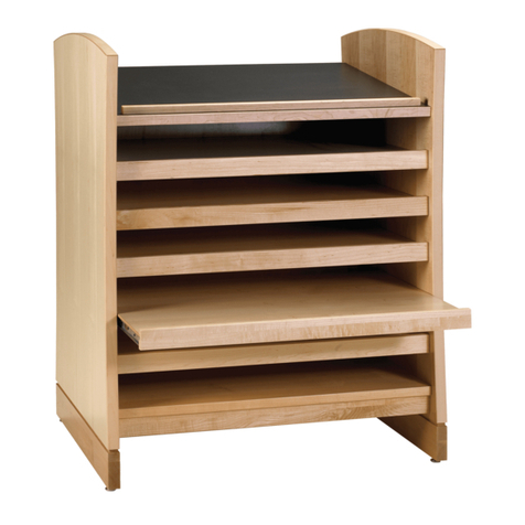
Note: The low cupboard padded
topper is an optional accessory that
must be ordered separately.
1. Place the padded topper on top of
the corresponding unit. The anti-skid
rubber strips located on the bottom
of the topper pad keeps sliding of the
topper to a minimum (Figure 9).
7
Tattoo™Storage - Low Cupboard - Door Hinge Adjustment
Assembly Instructions
Door Hinge Adjustment
Note: If doors on the low cupboard
are not aligned, follow instructions
below to adjust doors until square
on the unit.
1. For door height adjustment of
+/-2 mm, loosen the two height
adjust screws on each hinge and
move door up or down. Re-tighten
screws (Figure 10).
2. For door depth adjustment, first
loosen the depth adjust screw, then
slide the key hole of the hinge to
the desired location. Re-tighten the
screw (Figure 11).
3. For side-to-side adjustment, turn
the side-to-side adjust screw in or
out. The screw works in conjunction
with the inner leaf of the hinge arm to
move the door back or forth without a
change in gap between the door and
the cabinet (Figure 12).
4. To disassemble door from cabinet,
press the button on the rear of the
hinge tail inside the unit. Pull the
door slightly forward to disengage
the hinge connection. Repeat for the
other door hinge to remove the door
from the unit (Figure 13).
Figure 10 - Door Height Adjustment
door
hinge
Figure 11 - Door Depth Adjustment
door
hinge
keyhole
of the
hinge
Figure 12 - Side-to-Side Adjustment
side-to-side
adjust
screw
door
hinge
side-to-side
adjust
screw
door
hinge
Figure 13 - Door Removal
door
hinge
button on the
rear of the
hinge tail
Assemble units as described herein only. To do otherwise
may result in instability. All screws, nuts and bolts must be
tightened securely and must be checked periodically after
assembly. Failure to assemble properly, or to secure parts
may result in assembly failure and personal injury.
1330 Bellevue Street • P.O. Box 8100 • Green Bay, WI 54308-8100 • Tel 1-800-424-2432 • www.ki.com
© 2019 Krueger International, Inc. All Rights Reserved • Code KI-AI-000039R1/KI/PDF/0819
Tattoo™Storage - Low Cupboard
Assembly Instructions
Part # 2.57092

Other KI Indoor Furnishing manuals

KI Concerto User manual

KI

KI Concerto User manual

KI Sift Installation instructions

KI

KI Sift Installation instructions

KI All Terrain ATSW45 User manual

KI

KI All Terrain ATSW45 User manual

KI Concerto Installation instructions

KI

KI Concerto Installation instructions

KI Lancaster User manual

KI

KI Lancaster User manual

KI WorkUp HF User manual

KI

KI WorkUp HF User manual

KI System 3000 Countertop User manual

KI

KI System 3000 Countertop User manual

KI Trek TT-Base Folding Table User manual

KI

KI Trek TT-Base Folding Table User manual

KI Instruct User manual

KI

KI Instruct User manual

KI Ruckus Tote Storage User manual

KI

KI Ruckus Tote Storage User manual

KI Universal Overhead Storage User manual

KI

KI Universal Overhead Storage User manual

KI Likha Casegoods User manual

KI

KI Likha Casegoods User manual

KI CafeWay ECELP Maintenance manual

KI

KI CafeWay ECELP Maintenance manual

KI USPF2324 User manual

KI

KI USPF2324 User manual

KI Vertical Cable Manager User manual

KI

KI Vertical Cable Manager User manual

KI Extol Auditorium Seating Installation instructions

KI

KI Extol Auditorium Seating Installation instructions

KI WorkZone Series User manual

KI

KI WorkZone Series User manual

KI Genesis User manual

KI

KI Genesis User manual

KI Ruckus Desk User manual

KI

KI Ruckus Desk User manual

KI Uniframe Conver User manual

KI

KI Uniframe Conver User manual

KI Uniframe Convertible Bench User manual

KI

KI Uniframe Convertible Bench User manual

KI Unite System User manual

KI

KI Unite System User manual

KI WireWorks User manual

KI

KI WireWorks User manual

KI Concerto User manual

KI

KI Concerto User manual

Popular Indoor Furnishing manuals by other brands

Stanley HTC-275S Use and care guide

Stanley

Stanley HTC-275S Use and care guide

VonHaus 2500359 user manual

VonHaus

VonHaus 2500359 user manual

Robern CRAFT Series Important safety instructions

Robern

Robern CRAFT Series Important safety instructions

Argos Aurelie 531/6854 Assembly lnstructions

Argos

Argos Aurelie 531/6854 Assembly lnstructions

Pick Up PAULINE BKO Assembly instructions

Pick Up

Pick Up PAULINE BKO Assembly instructions

Fresco Allure Connect-12 instructions

Fresco

Fresco Allure Connect-12 instructions

burgbad Sana M1153 Instructions and operating manual

burgbad

burgbad Sana M1153 Instructions and operating manual

Zoovilla PTH0201721810 Care Instructions

Zoovilla

Zoovilla PTH0201721810 Care Instructions

Accuride 2109 installation guide

Accuride

Accuride 2109 installation guide

BLUM Aventos HK-S Assembly instructions

BLUM

BLUM Aventos HK-S Assembly instructions

Vinsetto 838-396V80 manual

Vinsetto

Vinsetto 838-396V80 manual

Emmezeta SEVILLA SEVK31 Assembling instructions

Emmezeta

Emmezeta SEVILLA SEVK31 Assembling instructions

Urban Barn Gabi 222389002 Assembly instructions

Urban Barn

Urban Barn Gabi 222389002 Assembly instructions

Forte MTBR711 Assembling Instruction

Forte

Forte MTBR711 Assembling Instruction

StyleWell BF-25648-WA Use and care guide

StyleWell

StyleWell BF-25648-WA Use and care guide

PEFC 875/4176 Assembly instructions

PEFC

PEFC 875/4176 Assembly instructions

GEIGER Tablet Installation principles

GEIGER

GEIGER Tablet Installation principles

Safavieh Furniture Ryder CNS5719 quick start guide

Safavieh Furniture

Safavieh Furniture Ryder CNS5719 quick start guide

manuals.online logo
manuals.online logoBrands
  • About & Mission
  • Contact us
  • Privacy Policy
  • Terms and Conditions

Copyright 2025 Manuals.Online. All Rights Reserved.