All Specifications are subject to change without prior notice.
TEMPERATURE CALIBRATOR
Preliminary Data
An ISO 9001:2008 Company
G-17, Bharat Industrial Estate, T. J. Road, Sewree (W), Mumbai - 400 015. INDIA.
Sales Direct.: 022-24156638, Tel. : 022-24124540, 24181649, Fax : 022-24149659
An ISO 9001:2008 Company
®
Chhaya com/D/chhaya/my documents/chhaya/backup/catlog/New catlog/2015 new arrival catalogs/KM-CAL-801.cdr
Model KM-CAL-801
ELECTRICAL SPECIFICATIONS - KM-CAL-801
í Basic Accuracy : ± 0.05%
í Display : 5 Digit LCD display.
í Max. Allowable Voltage : 30V..
í Operating Temperature Range : 0 ~ 50°C.
Humidity range : £ 80% RH
í Storage Temperature Range : £ -10°C ~ 55°C
Humidity range : £ 90% RH
GENERAL SPECIFICATIONS
This Calibrator is a source for Volts, Ohms RTD & Thermocouples. It gives output
of Volts in 2 ranges 100mV & 1000mV & also gives output of Ohms in 2 ranges
400W & 4000W & output for calibrating R, S, B, E, K, J, T & N type Thermocouples.
It also gives output for RTD Pt1000 & Cu50. It has very high accuracy 0.05%.
í Temperature Coefficient : 0.1 x (dedicated Accuracy) % /
°C (5°C ~ 18°C, 28°C ~ 40°C)
í Power Consumption : about 60m / 3V.
í Dimension : 180 (L) x 90 (W) x 47 (D) mm (with protector)
í Weight : About 500g
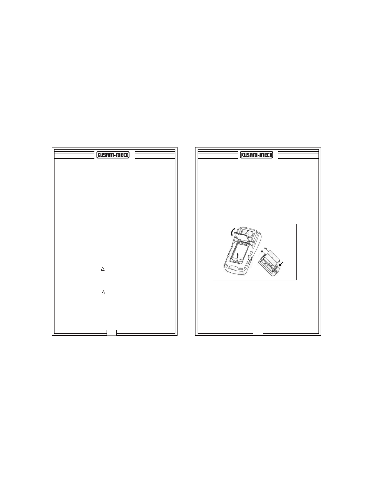
í Power : 1.5V x 2 alkaline batteries.
ACCESSORIES :
User Manual, Test lead CF-36, (Clips for probe),
Holster & Carrying case.
SAFETY :
Complies with IEC1010 (safety standard issued
by International Electrician Committee)
NEW
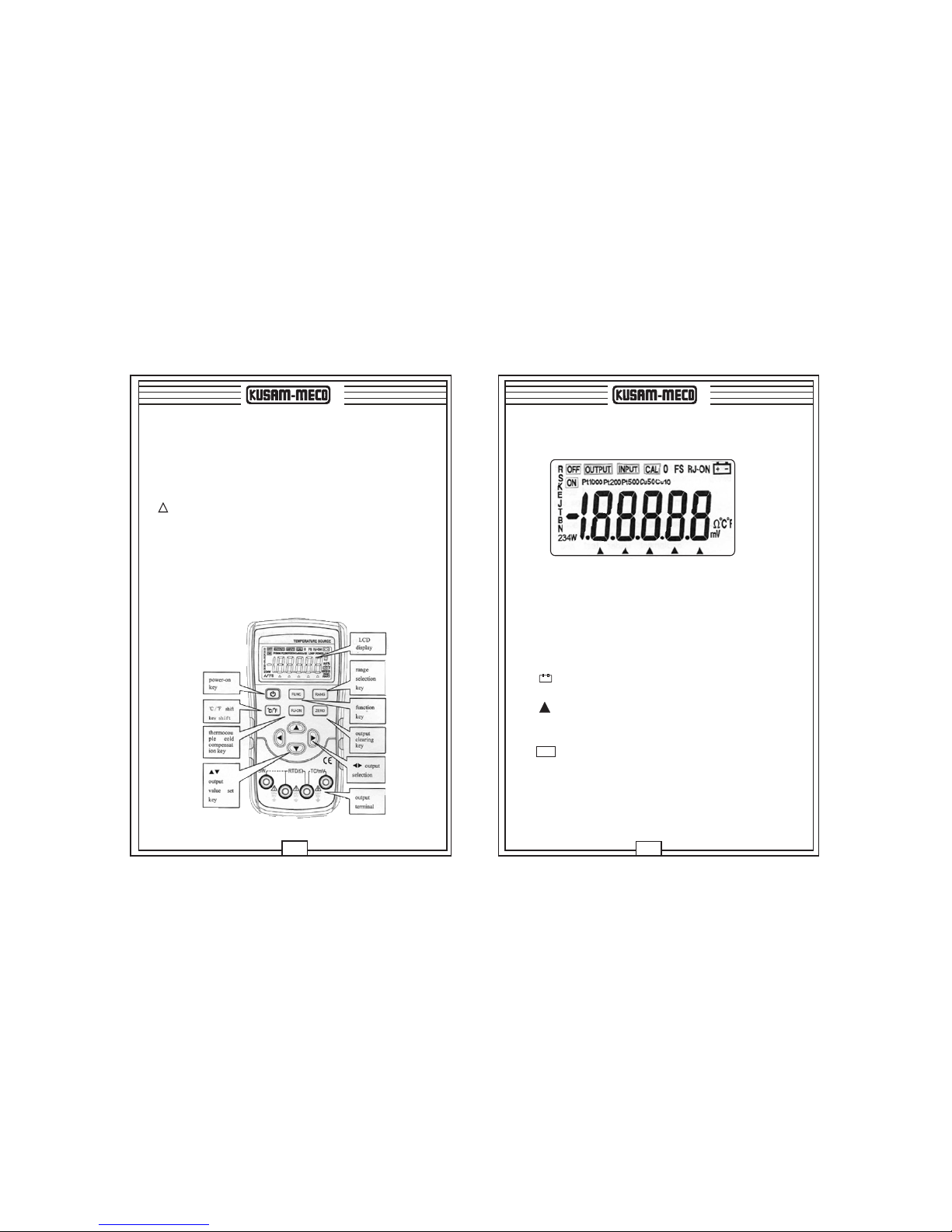
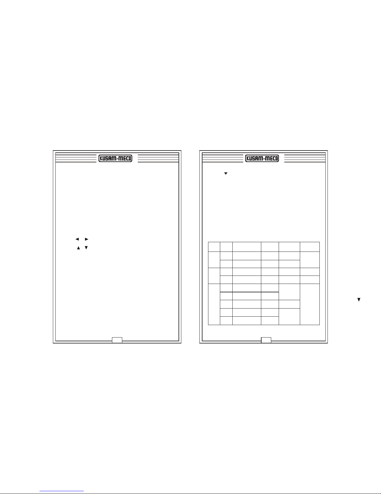
OUTPUT FUNCTION
100mV -10.00 ~ 110.00mV 0.01mV ±0.05% ± 30mVThe max. Output
current ± 2mA
DC Voltage
Output Remarks
Accuracy
Output Range Resolution
Range
1000mV -100.0 ~ 1100.0mV 0.1mV ±0.05% ± 0.3mV
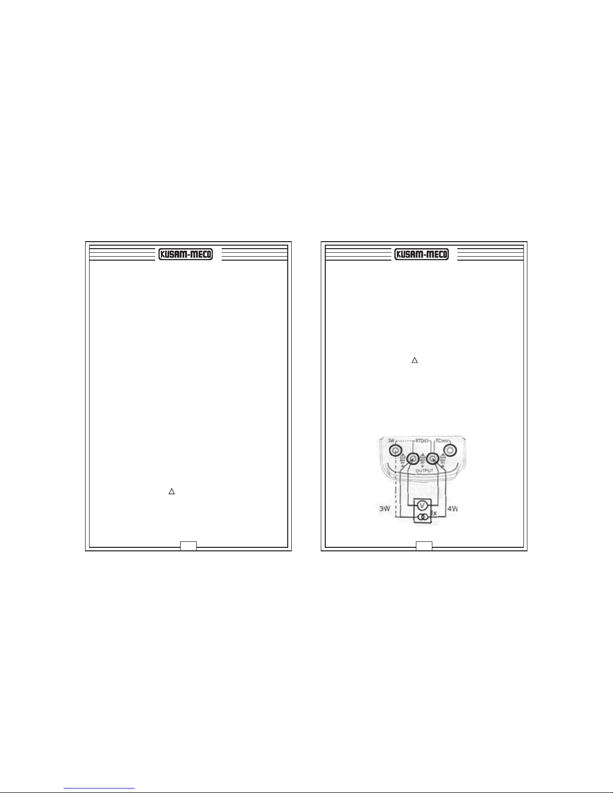
400W0.0 ~ 400.0W0.1W±0.05% ± 0.2W
OHM
4000W0 ~ 4000W1W±0.05% ± 2W
±0.05 ~ ±0.3mA
Affiliated resistance of test lead is excluded.
The range of incentive current is from
0.05mA to 3mA & the maximum output
is less than or equals to 2V.
R
S
B
E
K
J
T
N
O
-40 ~ 1760 C
O
-20 ~ 1760 C
O
400 ~ 1800 C
O
-200.0 ~ 1000.0 C
O
-200.0 ~ 1370 C
O
-200.0 ~ 1200.0 C
O
-200.0 ~ 400.0 C
O
-200.0 ~ 1300.0 C
O
1 C
O
1 C
O
1 C
O
0.1 C
O
0.1 C
O
0.1 C
O
0.1 C
O
0.1 C
±0.05% + 3°C
O
(Less than or equals to 100 C)
O
±0.05% + 2°C (more than 100 C)
Employs ITS-90
temperature
standard
The accuracy does not
include the error of
interior temperature
compensation sensor
the range of interior
temperature compensation
sensor is from -10 to 50°C
& the error compensation
is less than or equals to
0.5°C
Thermo-
couple
RTD
O
±0.05% + 3°C (400 ~ 600 C)
O
±0.05% + 2°C (more than 600 C)
±0.05% + 2°C
O
(Less than or equals to -100 C)
±0.05% + 1°C
O
(more than -100 C)
Cu10
Cu15
Pt10
385
Pt100
385
Pt200
385
Pt500
385
Pt1000
385
O
-10.0°C ~ 250.0 C
O
-50.0°C ~ 150.0 C
O
-200.0°C ~ 850.0 C
O
-200.0°C ~ 850.0 C
O
-200°C ~ 630 C
O
-200.0 ~ 1200.0 C
O
-200.0°C ~ 630.0 C
O
0.1 C
O
0.1 C
O
0.1 C
O
0.1 C
±0.05% + 0.6°C
O
0.1 C
O
0.1 C
O
0.1 C
Incentive Current is
±0.5 ~ ± 3mA
When the incentive
current is ± 0.1 ~ 0.5mA,
add 0.5°C additional
error
Incentive Current is
±0.05 ~ ± 0.3mA
±0.5 ~ ±3mA
Affiliated resistance of test lead is excluded.
The range of incentive current is from
0.05mA to 3mA & the maximum output
is less than or equals to 2V.