LCN 8310-2410 User manual

Model 8310-2410 Installation Instructions
Description
Actuators
Available faceplates:
Double Gang “Wave to Open” actuator with light ring
Double Gang “Wave to Open” actuator without light ring
Single Gang “Wave to Lock” actuator with light ring
E-strike
Provided faceplates:
• 4-7/8” x 5/8” (ANSI Square/Hollow Metal)
• 6-7/8” x 5/8” (Aluminum)
• 7-7/8” x 5/8” (Wood Door)
• Transformer
• Open style, channel bracket, two-hole chassis mount.
• 120 VAC @ 60 Hz.
• Minimum 6” leads
• Class B insulation (130° C)
Cabinet
• 11 ⁄” x 7 ⁄” x 2 ⁄”
• Power supply (blue circuit board), Relay Module (green
circuit board), and two terminal buses.
• Must be set to 24VDC output
Parts lists
Main parts list
Item
#Description Quantity
1 “Wave to Open” Switch w/o Light Ring 1
2 “Wave to Open” Switch w/ Light Ring 1
3 "Wave to Lock" Switch 1
4 Power Supply/Relay Cabinet 1
5 Door position switch 1
Item
#Description Quantity
6Vinyl Plaque “Door locked when red/
unlocked when green” 1
7Vinyl Plaque “Door occupied when
red/vacant when green” 1
8 E-Strike w/ 3 faceplates 1
9 Transformer 1
E-strikes parts list
Item
#Description Quantity
1E-strike (comes pre-installed w/ ANSI
faceplate) 1
2 Aluminum faceplate 1
3 Wood faceplate 1
4Faceplate template 3
5 24V female connector 1
6 Varistor (MOV) 1
7 Trim plate 1
8 Mounting brackets 2
9 Wire nuts 4
10
#10-32 x ½” machine screws
(installed w/ ANSI faceplate on
e-strike)
2
11 #10 - 1¼” wood screws (for mounting
brackets) 2
12 M5 x 12mm machine screws (for
mounting brackets) 5
8310-2410 Touchless Restroom Kit
CAUTION
The product warranty will be voided if the product is mounted for an exterior door and/or is exposed to elements.
For cleaning purposes, do not expose components to extreme wash-down.
The electric strike is not water-proof.

Technical specifications
Actuators
Actuators with light ring Actuator without light ring
(Outside Wave to Open/Inside Wave to Lock) (Inside Wave to Open)
No. of IR sensors 2 Body size 4” x 1” x 1 ½”
Operating voltage 12 - 24 volts, AC/DC ± 10% Mounting 2 x #6-32 MS
Current draw 40 mA Faceplates
sizes Jamb, Single gang, Double gang
Standard operating
range
1” - 28” (25.4 mm - 71.2 mm)
Factory set to 12” (304 mm) Technology Infra-red with coded modulated carrier
Auto range
operation
6” - 40” (152.4 mm - 1.016 m) hand
6” - 72” (152.4 mm - 1.820 m) body Security Automatic self-changing ID
Relay contact rating 3 amps @ 30 V DC Operating
modes Pulse (sense)/Toggle
Output type Fail safe or Fail secure Operating
temperatures -4° to +153°F (-20° to +85°C)
Inputs - “Request to Exit”
- External (Door contact) input
Operating
voltage 12 - 24 Volts, AC/DC ± 12%
Optional LED ring On/Off, red, blue, green Current draw 50 - 60 mA
Current draw 8 mA max. Response time 100 ms
Operating modes
Motion sensing
modes
Relay operation
modes
- Momentary
- Momentary with alarm
- Maintained (latching)
- Single event
- Toggle
Activation
range
Minimum: 2”
(51 mm)
Maximum: 18”
(457 mm)
Factory set to: 6”
(152 mm)
Relay output 1 form “C” (SPDT) Relay output Form C (SPDT)
Relay contact
rating 5 Amps @ 30 VDC
Output type Normal or Fail-safe
Connections 11” 22 AWG leads
Time delay 1 - 5 seconds
Electrical life 100,000 operations at rated capacity
500,000 operations at ½ rated capacity
E-strike
Descriptions 8310-2420 Series
Voltage 24 DC
Current Draw 150 mA maximum @ 24 VDC
Static strength 1000 lbs.
Dynamic strength 50-. lbs.
Mode Field selectables
Fail safe/fail secure
Mechanical adjustment Strike body/faceplate
Operation DC-silent
Duty Continuous
Dimensions (body) 3 3/8” x 1 7/8” x 1 7/32” (86 mm x 47 mm x 31 mm)

Transformer
Descriptions 8310-2410 Series
Input voltage 120V AC
Output voltage 24V AC @ 60 Hz
Class B2
Power 50 VA
DPS Switch
Descriptions 8310-2420 Series
Power max. 3.0 W
Electrical configuration SPDT
Suggested Wiring 22AWG
Gap distance max. 0.75”
Operation at a glance
When the outside WAVE TO OPEN touchless switch is activated it will trigger its N.O. relay contact to send a momentary
closure to the restroom kit allowing the door to swing open. When the interior WAVE TO LOCK touchless switch is
activated it will trigger its N.O. relay contact to send a momentary closure to the restroom kit to lock the Restroom and
switch the light rings color from green to red. The inside WAVE TO OPEN, when activated, will unlock the door and the door
will swing open. The restroom can also be unlocked by opening the door from the inside which will break the door contact
circuit causing the restroom kit to reset and unlock the door. The light rings will switch back to green, indicating that the
restroom is now vacant.
Installation
1 Mounting
LIMPORTANT: Do not apply power to the unit until you have fully read the instructions and have made the required
adjustments!
The touchless actuators may be mounted in conventional plastic electrical gang boxes. Ensure that the unit sensor does
not come in contact with any metal components within the gang box to avoid damaging the unit. Do not place the sensor
in the door’s opening range, where the sensor may see door movement. Do not place moving objects in front of the sensor.
Always use the given foam gasket. For the installation of electrical gang boxes from other manufacturers, refer to the
mounting box instructions that come with the product.
Actuators
The touchless actuators may be mounted in single gang or double gang electrical boxes, and 4 x 4 boxes.
LNOTE: Actuators are for interior use only!
Single/double gang mount box
LNote: Electrical boxes for all installations are needed, but not included. For the electrical box installation, refer to
the mounting box instructions that come with the product.
1a If using an in-wall box ensure the box is square and flush with the wall surface. If using a surface box, ensure it is secure
and flush. If using a 4 x 4 box, ensure the box is square and flush with the wall surface, then attach the metal adaptor
plate (included in the packages) to the box using appropriate fasteners.
1b Bring your 4 or 6-conductor wire through the back or side of the enclosure and leave approximately 6” tail for wiring
connection.
1c Make the electrical connections to the device according to the wiring section.
1d Using the dip switch located on the end of the unit, set the operating mode.
1e Attach the unit to the enclosure using the two #6-32 screws provided.
1f Apply power and adjust range and time delay via the potentiometers on the front of the unit.
1g Attach the faceplate to the unit using the two black #6-32 x 1/2’’ machine screws or tamperproof screws.
1h Apply the label as required.
LNote: Do not overtighten screws!

Single gang box mount
Wall
Wall
Label
Label
Surface Mount Flush Mount
Wall
Wall
Label
Label
Surface Mount Flush Mount
Double gang box mount
Label
Faceplate
Wall
Adapter Plate
Gasket Surface Mount Enclosure
#6-32 x 3/4” (2 Pcs)
#6-32 x 1/2”
(2 Pcs)
Polypropylene
Lens Holder Set
Gasket
IR Lens
Faceplate
Faceplate
E-strikes
LNote: This can only be used with cylindrical locks. These cannot be used with mortise locks, deadbolts, or rim
exit devices. Allegion suggests a storeroom function for a cylindrical lockset when paired with an e-strike (ex. the
Schlage ND-Series ND80).
LNote: this e-strike is not rated for preloading (pressure against the strike when the door is closed).
1a Prepare the door jamb, per the appropriate drawing.
1b Confirm whether the strike is for fail safe or fail secure mode.
1c Install the mounting brackets to the jamb using M5 x 12mm screws and pressed metal nuts. Do not tighten.
1d Wire the e-strike to terminals within the cabinet. Refer to the e-strike wiring section for more details.
1e Install the electric strike jamb by attaching with #10-32 screws and lock washers.
1f Secure M5 x 12 screws hold mounting brackets to jamb.
How to modify fail-safe to fail-secure, or vice versa.
1a Loosen the screw, as per the product diagram below.
1b Rotate the set plate 180° and slide the plate until it is properly seated.
1c Tighten the screw.
Fail-Lock mode when
Mode Selector is pointing to Fail Lock
Fail-Safe mode when
Mode Selector is pointing to Fail Safe
Fail-Safe mode when
Mode Selector is pointing to FS
Set Screw
Mode Selector
Mode Selector Set Screw

Note: The products are intended to be installed in accordance with the installation wiring diagram, mechanical
assembly drawings provided with each product, the local authority having jurisdiction (AHJ) and the National Electric
Code, NFPA 70. When installed in fail secure mode, the local authority shall be consulted with regard to the use of
possible panic hardware to allow emergency exit from the secure area.
The electric door strike shall be installed in such a way and in such a location so as to not impair the operation of an
emergency exit device or panic hardware mounted on the door.
Mounting Bracket
Spacer
(optional by others)
Spacer
(Optional by others)
Spacer
(Optional
by others)
M5x12mm Flat-Head Screw (2pcs)
Optional Trim Plate
Jamb
M5x12mm
Flat-Head
Screw
(86mm)
3-3/8” (86mm)
3-3/8”
(31mm)
1-7/32”
(31mm)
1-7/32”
(105mm)
4-1/8”
(124mm)
4-7/8”
(89mm)
3-1/2”
(155mm)
6-1/8”
(173mm)
6-7/8”
(144mm)
5-11/16”
ANSI square/Hollow metal Aluminum
(86mm)
3-3/8”
(187mm)
7-3/8”
(36mm)
1-3/8”
(200mm)
7-7/8”
(168mm)
6-3/8”
(31mm)
1-7/32”
Wood
(86mm)
3-3/8” (86mm)
3-3/8”
(31mm)
1-7/32”
(31mm)
1-7/32”
(105mm)
4-1/8”
(124mm)
4-7/8”
(89mm)
3-1/2”
(155mm)
6-1/8”
(173mm)
6-7/8”
(144mm)
5-11/16”
ANSI square/Hollow metal Aluminum
(86mm)
3-3/8”
(187mm)
7-3/8”
(36mm)
1-3/8”
(200mm)
7-7/8”
(168mm)
6-3/8”
(31mm)
1-7/32”
Wood
Optional trim plate installation
Used for retrofit installation, if gaps need to be filled in.
Jamb
Jamb
Jamb
Jamb
Jamb Jamb

Cabinet
LIMPORTANT: Do not apply power to the unit until you have fully read the instructions and have made the required
adjustments!
The 8310-2410 cabinet should be mounted in a clean, dry location out of direct contact with the elements. The cabinet
base dimensions can be seen on the separate cabinet base template (on page 16).
DPS Switch
LNOTE: The gap distance should not exceed 0.75”.
1a Determine mounting location on the door frame.
1b Mark and drill two holes for mounting the switch.
1c Mount the switch to the frame with the screws.
1d Align the magnet on the door with the switch.
1e Mark and drill two holes for the mounting magnet.
1f Mount the magnet with the screws.
Transformer
The transformer should only be installed OUTSIDE of the Power Supply Cabinet per all National Electric Code (NEC) /
NFPA 70 requirements along with local code requirements, and it should be kept in close proximity to the Power Supply
Cabinet. For verification of code compliance, we recommend reaching out to the AHJ (Authority Having Jurisdiction), which
may be your local Fire Marshall. Pending approval from the AHJ, the transformer may be mounted to the side of the Power
Supply Cabinet (requires drilling) or mounted in a separate utility box to house it (typically installed by an electrician). As
previously stated, the installation will need to be compliant with all local and NEC requirements.
Black
Black
Red
Red
Primary
(120V AC)
Secondary
(24V AC)
Transformer Schematic
31
8''
[78.48mm]
7
8''
[22.35mm]
21
8''
[55.50mm]
13
4''
[44.70mm]
2
5
8''
[66.68mm]
21
4''
[55.88mm]
0''
[1.27mm]
Ă1
8''
[3.81mm]
13
8''
[34.80mm]
21
4''
[57.15mm]
17
8''
[47.63mm]
13
4''
[43.18mm]
Ă1
8''
[4.76mm]
1''
[25.40mm]
3
3
4''
[93.73mm]
TYP
TYP
OPEN STYLE FILAMENT & L.V. RECTIFIER USE
TRANSFORMERS
2 Wiring
CAUTION
Do not apply power to the unit until all secondary wiring is complete, and dip-switches have been set.
All applications
The 8310-2410 comes with the relay module pre-wired to a labeled set of two terminal strips. A complete wiring diagram is
adhered to the inside of the door to provide a layout of the wiring as a reference when wiring the field devices to the kit.
There are two terminal strips that mirror the locations on the relay module. The le strip is used for power to the relay
module, the WAVE TO OPEN and WAVE TO LOCK actuators, the door position switch, and the Wet trigger. The right strip is
for the outputs to drive the strike (Relay 1), door operator (Relay 2), light rings (Relay3), and to provide VDC power for the
door strike.
Once all field devices are wired to the 8310-2410, then AC power can be wired in.
LNote: Light rings come installed.
LIMPORTANT: Confirm the electrical panels breaker you are going to be using is currently off. Do not wire the
primary terminals of the transformer until the secondary terminals are connected first.
The supplied transformer will have its red secondary wires connected to the terminals on the top of the le terminal strip
marked as “AC”. Next, connect the black primary wires to the AC feed to be used. Confirm your connections and apply power
by turning on the electrical panels breaker.

Black
Black
Red
Red
Primary
(120V AC)
Secondary
(24V AC)
Transformer Schematic
31
8''
[78.48mm]
7
8''
[22.35mm]
21
8''
[55.50mm]
13
4''
[44.70mm]
2
5
8''
[66.68mm]
21
4''
[55.88mm]
0''
[1.27mm]
Ă1
8''
[3.81mm]
13
8''
[34.80mm]
21
4''
[57.15mm]
17
8''
[47.63mm]
13
4''
[43.18mm]
Ă1
8''
[4.76mm]
1''
[25.40mm]
3
3
4''
[93.73mm]
TYP
TYP
OPEN STYLE FILAMENT & L.V. RECTIFIER USE
TRANSFORMERS
Actuator wiring
Wiring the Outside WAVE TO OPEN actuator with light ring
Wire in power from the VDC +/- terminals in the control box to the TB6 terminal block on the back lower le side (not
polarity sensitive). On terminal block TB1, wire the common and normally open poles of the relay to the “Outside Wave to
Open” terminals on the le terminal bus inside the control box. Remote terminal 1 (TB5) will be wired in parallel with the
Remote terminal 1 (TB5) of the WAVE TO LOCK actuator (polarity sensitive). The same will be done with Remote terminal
2 (TB5) of both actuators.
Both will be connected to the “LED Control” terminals (not polarity sensitive) on the right terminal bus inside the control box.
Confirm the DIP switch settings using the wiring diagram legend on page 15. Adjust the range accordingly with POT1 and
POT 2 for the desired activation time.
Wiring the “Wave to Open” actuator without light ring
Wire in power from the VDC +/- terminals on the le terminal bus of the control box to the two red wires on the back of the
sensor. Next, connect the blue wire and the green wire to the “Inside Wave to Open” terminals on the le terminal bus of the
control box.
The range and the activation time can be adjusted from the front face of the sensor. The range adjustment is on the top and
the activation time is located on the bottom.
Begin adjustments with both pots turned fully counterclockwise.
Wiring the “Wave to Lock” actuator with light ring
Wire in power from the VDC +/- terminals in the control box to the TB6 terminal block on the back lower le side (not
polarity sensitive).
On terminal block TB1, wire the common and normally open poles of the relay to the “Inside Wave to Lock” terminals on the
le terminal bus inside the control box.
The Remote terminal 1 (TB5) will be wired in parallel with the Remote terminal 1 (TB5) of the outside “Wave to Open”
actuator with light ring (polarity sensitive). Both will be connected to the “LED Control” terminals (not polarity sensitive)
on the right terminal bus inside the control box. The same will be done with Remote terminal 2 of the “Wave to Lock” and
outside “Wave to Open” actuators.
Confirm the DIP switch settings using the wiring diagram legend on page 15. Adjust the range accordingly with POT1 and
POT2 for the desired activation time. Please refer to the setup section for more adjustment details.
Once all field devices are wired to the restroom kit then AC power can be wired in.

E-strike
A varistor is provided to protect/prevent strike from spikes. Connect varistor between input wires.
LThe 24V Black and
Red wires from the
female connector will
wire to the VDC+ and
VDC- terminals in the
Power Supply/Relay
Cabinet
Red
Black
Blue
Green
Male
Connector
Female
Connector
Black
Red
Blue
Green
(+24V)
( - )
24V
Varistor
Power
Red wire
Black wire
Female
Connector
Transformer
Refer to the graphic below to wire the transformer.
Black
Black
Red
Red
Primary
(120V AC)
Secondary
(24V AC)
Transformer Schematic
31
8''
[78.48mm]
7
8''
[22.35mm]
21
8''
[55.50mm]
13
4''
[44.70mm]
25
8''
[66.68mm]
21
4''
[55.88mm]
0''
[1.27mm]
Ă1
8''
[3.81mm]
13
8''
[34.80mm]
21
4''
[57.15mm]
17
8''
[47.63mm]
13
4''
[43.18mm]
Ă1
8''
[4.76mm]
1''
[25.40mm]
33
4''
[93.73mm]
TYP
TYP
OPEN STYLE FILAMENT & L.V. RECTIFIER USE
TRANSFORMERS
DPS switch
Wire the switch as needed for the application.

3 Set-up
LNOTE: The red dip switches (power supply dip switches) need to be set for 24V.
- Dip switch SW1 should be set to OFF
- Dip switch SW2 should be set to ON
All applications
Selecting a Mode
The restroom kit has two Restroom applications built in
(Modes M 7 & M 8). The default mode for the restroom kit
is Mode M 7 (Fail Safe).
Determining which mode is correct for you will be based on
whether the e-strike is set to Fail Safe (Mode M 7) or Fail
Secure (Mode M 8).
There are three LED displays that will allow you to see
what mode you have selected when advancing through the
modes.
To change the mode of the restroom kit, simply press the
MENU button once and use the UP button to advance to the
desired mode.
Editing the Settings for a Mode
Typical times are pre-set for lock release and door operator
activation and is ready to use without changing any
parameters. If you need to change the timing or delay for an
output, it can be done by pressing the “MENU” button within
the mode you selected.
Once the option is selected you can use the “UP or DOWN”
buttons to select the timing needed. The first option (H & 1
flashing) will be how long relay 1 will be activated for (0-50
seconds).
The second option (d & 1 flashing) will be how long to wait
before activating relay 2 (0-15 seconds).
The third option (H & 2 flashing) will be how long relay 2 will
be activated for (0-50 seconds).
The fourth option (d & 2 flashing) will be how long to wait
before activating relay 3 (0-15 seconds).
The fih option (H & 3 flashing) will be how long relay 3 will
be activated for (0-50 seconds). See chart below.
Factory Reset (Defaulting the Relay Module)
To return the relay module back to its factory default settings
you will need to remove power, then hold down the “MENU”
button while powering up the relay module.
Once started you will see the firmware version listed then
a number “1” will be displayed. Reconnect your power and
press the “MENU” button once then use the “UP” or “DOWN”
button to advance to the desired mode.
Fully test the operation of the restroom kit for proper
functionality.
Display (M) Description (Mode you are in) Parameters (1-15)
H, then 1 Relay 1 hold time 0.0 to 50 seconds
d, then 1 Relay 2 delay time 0.0 to 15 seconds
H, then 2 Relay 2 hold time 0.0 to 50 seconds
d, then 2 Relay 3 delay time Depends on mode
H, then 3 Relay 3 hold time 0.0 to 50 seconds
d Sets the display ON or OFF during operating mode ON or OFF
AInput delay on Activate. If other than 0.0 is selected, the input must be held
in for the time period chosen before the relay module will activate. 0.0 to 10 seconds
1 Set Dry Input 1 to activate on normally open or normally closed contact. N/O or N/C
2 Set Dry Input 2 to activate on normally open or normally closed contact. N/O or N/C
3 Set Dry Input 3 to activate on normally open or normally closed contact. N/O or N/C
4 Set Dry Input 4 to activate on normally open or normally closed contact. N/O or N/C
5 Not used. Not used
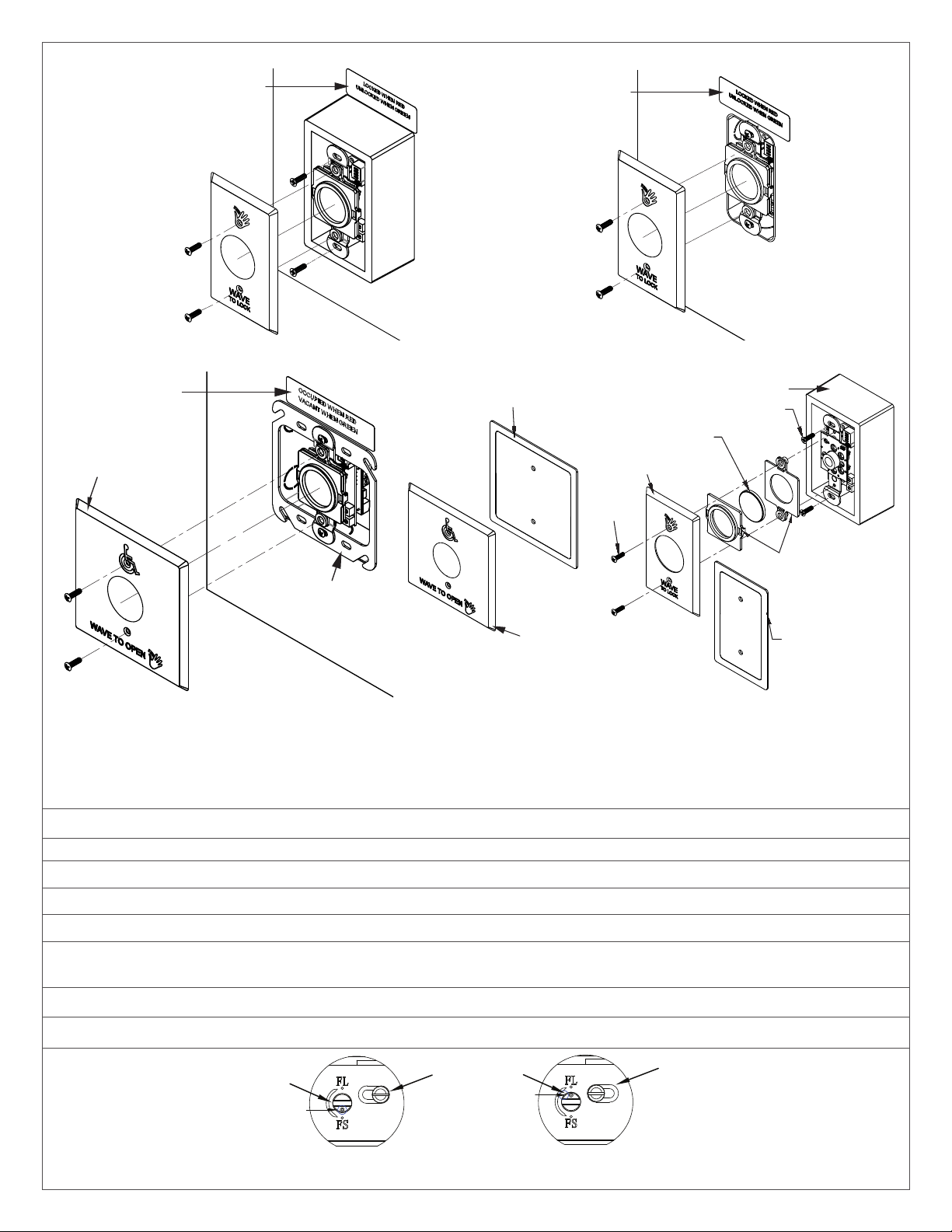
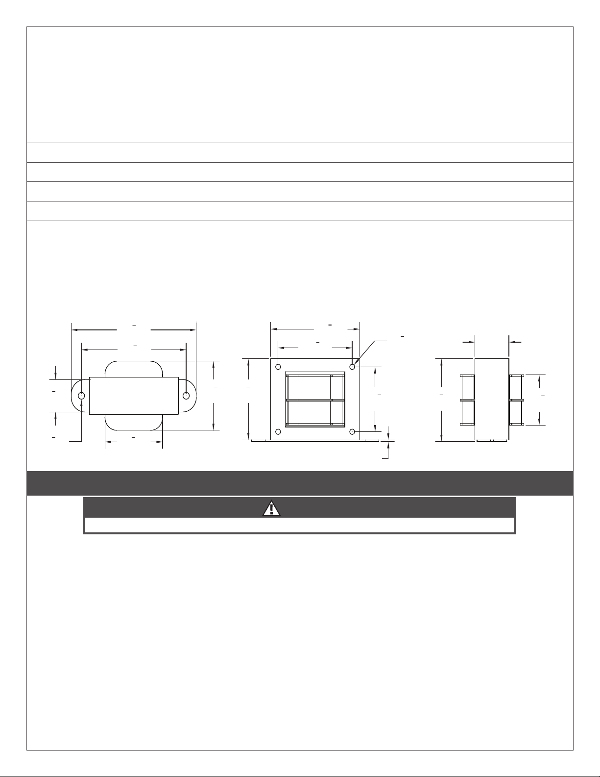
Actuators
The Outside Wave to Open/Wave to Lock with light ring actuators
LCAUTION: Do not apply power to the unit until all secondary wiring is complete and dip switches have been set.
Power — TB6
The actuators is powered by 24VDC. Connect the power to pins 1 and 2 on TB6. This is a non-polarized connection. Connect
VDC +/- from right terminal bus of Control Box to screw terminals on TB6 (not polarity sensitive).
Inputs
The actuators provide inputs for door contacts, Request to Exit and remote control of the LED light ring. These inputs are
found on TB2. All inputs require a dry contact closure to operate.

TB3-5 Inputs
Terminal Function Description
TB3, Terminals
1 & 2 Request to Exit A dry contact closure across these inputs will activate the
relay(s) as per their settings.
TB4, Terminals
1 & 2 Door Contact Normally closed, Used for Security Mode
TB5, Terminals
1 & 2 Remote LED External light ring control. A closed dry contact on this
input will toggle the light ring color.
Outputs
The actuators provide Form ‘C’ relay outputs. Both the single gang & double gang actuators with light rings have 1 Form ‘C’
output. Selecting the correct output is also dependant on the operating mode chosen. Most applications will utilize the
N.O. and Common terminals.
Relay 1 Output (TB1)
Relay 1 output (TB1)
Description
1 Normally closed
2 Common
3 Normally Open
12
O
N
4
3
Activate
LED
Sounder
Error/Alarm
LED
POT 1
Range
Adj.
LED Enable
Audio Enable
12
O
N
4
3
Motion Sensing
Modes
Relay Operation
Modes
Fail Safe
EXT
Relay
OP Time
DIP 1 DIP 2
POT 2
J 1
Power In
Power In
N
O
C
N
C
12
O
N
4
3
LED Control
DIP Switch
TB6
TB1
1
2
2
1
2
1
DIP 3
TB 2
Relay
1
TB3
TB4
TB5
DIP switch 1 – Options switch
SW1 – LED Enable
When SW1 is ON, the green LED will illuminate when the switch is activated. When SW 1 is OFF (default), the green LED will
remain off.
SW2 – Audio Enable
When SW2 is ON, an audible beep is generated when the switch is activated. When SW2 is OFF (default), no audible beep
is generated.
SW3 – Normally Open/Normally Closed
This option changes the state of the relays on the switches. When SW3 is OFF, the relay outputs are switched. NO
becomes NC and NC becomes NO. SW3 is ON by default.
SW4 – External LED Control
The LED light ring can be controlled externally by providing a contact closure on the REM input terminals on TB5. When
SW4 is ON, a contact closure across the REM input will change the light ring color from its idle to active colors. When SW4
is OFF, the light ring colors change with the state of the switch.

DIP switch 3 – Light ring DIP switch
SW1 SW2 SW3 IDLE ACTIVE
OFF OFF OFF No Color No Color
OFF OFF ON Green Blue
OFF ON OFF Blue Green
OFF ON ON Green Red
ON OFF OFF All OFF Blue
ON OFF ON Red Blue
ON ON OFF Red Green
ON ON ON Blue Red
DIP 1 SW4 – External Light Ring Control
ON = Enabled, OFF – Disabled
When SW4 is ON, the light ring changes color according to the above table but will follow the state of the External Input on
TB5.
Open = Active Closed = idle
When SW4 is OFF, the light ring changes color according to the above table but follows the status of relay 1.
DIP2 – Mode Switch
DIP 2 switches 1 & 2 control the Motion Sensing Modes. There are 4 Motion Sensing modes available described in the table
below.
DIP 2 switches 3 & 4 control the Relay operating modes. There are 4 Relay operating Modes available described in the
table below.
Relay Operating Mode
Mode Operation
Operational
Mode Name SW3 SW4
Simple mode OFF OFF Only relay 1 operates
Sequenced
mode - -
Relay 1 operates,
delay, relay 2 operates
sequenced fashion
Toggle mode ON ON Toggle mode – relay 1
toggles
Simple Mode
When an object is in range of the sensor, only Relay 1 will operate. Relay 1 will operate for the amount of time set by POT 2.
Toggle Mode
When an object is in range of the sensor, Relay 1 will activate. Relay 1 remains activated until an object is in range of the
sensor again.
Motion Sensing Modes
Mode Name SW1 SW2
Momentary OFF OFF
Operates momentarily, will not re-engage unless object is
removed first and then put back. No audio or visual alarm
triggered.
Momentary
with Alarm ON OFF
Operates momentarily, will not re-engage unless object is
removed first and then put back. Alarm (audio and visual)
generated if object remains in front of unit for 30 seconds.
Operate and
stay operated
– no alarm
OFF ON Unit will continue to operate, relays stay engaged. No audio or
visual alarm triggered.
Auto Range
Mode ON ON
Stuck on condition is approx 10 inches. Normal operation in
this mode is the same as SO Mode 0/1 (dependant on number
of relays). Unit will sense environment and automatically
shrink the envelope in response to environment. Use this
mode to sense across a hallway with range set to maximum.
There are 4 Motion Sensing modes available described in the table below.

Momentary
When an object is in range of the sensor, the actuator operates momentarily. It will not operate again until the object is
removed and presented again. If the object remains in range of the sensor, no alarms are generated.
Momentary with Alarm
When an object is in range of the sensor, the actuator operates momentarily. It will not operate again until the object is
removed and presented again. If the object remains in range of the sensor for more than 30 seconds, an audible and visual
alarm is generated.
Maintained
When an object is in range of the sensor, the actuator activates and stays activated for as long as the object is in range of
the sensor. Once the object is removed, the actuator deactivates.
Auto Range
The Auto Range Mode continually senses the environment and adjusts the actuator accordingly to eliminate false triggers.
The actuator will calibrate itself with the first stationary object detected. Objects in motion behind the stationary object
are not detected, but objects in motion in front of the stationary object are detected by the actuator. If another stationary
object is place in front of the original stationary object, the actuator re-calibrates itself against the new stationary object.
Objects in motion between the old stationary object and the new stationary object are not detected while objects in
motion between the actuator and the new stationary object are detected.
Adjusting the Range
The range on this unit has been set to approx. 12” at the factory. If the desired range is less than 12”, turn the range
adjustment (POT 1) counterclockwise until the range is set. Use a piece of paper or your hand to test the range. If the
desired range is greater than 12”, but less than 24”, turn the range adjustment (POT 1) clockwise until the range is set. Use a
piece of paper or your hand to test the range.
All actuators have easy field adjustment of operating
range, up to 28”.
Actuators with light rings can be set to automatically detect
the operating range to a stationary object (i.e. wall, railing or
cart) placed in range of the switch, up to 72” distance. If the
stationary object is moved, the switch will automatically adjust
to suit the changed condition.
Switch 1 – Normal Mode/Fail-Safe Mode
Choose Normal Mode if you wish the N.O. contact to remain open if the power were to fail. This is the factory setting.
Choose Fail-safe Mode if you wish the contacts to close upon power fail. Move the Dip switch to OFF position, and wire
your device to the Common and N.C. wires.
Switch 2 – Actuation Time Mode/Toggle Mode
Factory setting is Actuation Time (Pulse) mode, whereby the contact closure will be adjustable from 1 – 5 seconds using
the Time Delay Potentiometer.
In Toggle (or Switch) mode, when the CM-325 is activated once, the relay will stay energized until it is activated once again.
(The adjustable timer is inactive in this mode)

Switch 3 – LED On/LED Off
This switch disables the LED, should this feature be desired. Factory setting is ON.
Once the Dip switches have been set, and the unit is installed in the frame or enclosure, apply power to the unit and
observe operation.
Set both potentiometers to minimum setting initially (fully counter-clockwise). Adjust the range potentiometer by turning
the pot in a clockwise manner, and passing your hand in front of the unit. Rotate the pot until the desired range is obtained.
See Diagram 5 for patterns.
Next, adjust the time delay potentiometer by turning clockwise until the desired time delay is obtained. It is sometimes
beneficial to leave this adjustment set to minimum and utilize the time delay on the door operator, if present.
LNOTE: Timer is non-functional in Toggle Mode. Install the faceplate using the screws provided.
LNOTE: Do not overtighten!!
Photo Eye
Red LED
Time Delay
Adjustment
Dip Switch
Red
Red
Blue
Green
Violet
12-24V
Power
N.O.
COM
N.C.
Range
Adjustment Wiring Pigtail
Actuator without light ring
Location of Adjustments

4 Restroom signage
Place Sign
On The Door
Inside The Restroom
At Eye Level
INSIDE THE
RESTROOM
Indicator on switch will turn red when door is locked.
USE ''WAVE TO LOCK'' SWITCH
TO LOCK THIS DOOR
WAIT FOR DOOR TO CLOSE
40-81C024
LOCKED WHEN RED
UNLOCKED WHEN GREEN
WAVE TO OPEN WAVE
TO LOCK

5 Wiring diagram
8310-2410 Touchless Wiring Diagram
Door Position Switch
Transformer
24 VAC, 50 VA
Outside
Wall Switch
Inside - Wall Switch
(always unlocks/opens door)
Inside - Wave to Lock
Electric Strike
Wire MOV
directly to
strike or
magnet
120 VAC
N.C.
AC
AC
Outside
Inside
Wave To Open
Wave To Open
Wave To
Lock
DPS NC
DPS COMM
+ WET
-INPUT
*
+ Strike
Strike
-
*
Door
Operator
*
LED
Control
*
+ VDC
- VDC
WAVE
TO LOCK
12/24V
Power
Remote N.O.
Relay Output
WAVE TO OPEN
12/24 V
Power
Remote N.O.
Relay Output
TB6 TB5 TB1 TB6 TB5 TB1
1 2 1 2
WAVE TO OPEN
RED
RED
BLUE
GREEN
POWERRELAY O/P
Dip Switch
Settings
Notes
1. Relay module can be set to Mode 7 (Normally Unlocked)
or Mode 8 (Normally Locked).
2. Mode 7 = Set Set Strike to Fail Safe.
3. Mode 8 = Set Strike to Fail Secure .
1LED
Audio
Fail Safe
EXT
2
3
4
Enable (DIP 1)
ON
1IDL = GREEN
ACT = RED
2
3
4
Mode (DIP 2)
ON
1
2
3
4
Color (DIP 3)
ON
= Switch Position
IMPORTANT:
Ensure wiring polarity is consistent from
Relay 3 to each Aura Remote Input terminals
MOV
NOTE: See the Auto Operator
Wiring Table for activation
terminals.

6 Cabinet base template
9⁵⁄8"
6"

7 Auto Operator Wiring
Auto operator COM NO
4630/4640 Series Electric Auto-
Equalizers
Terminals 17 or 19 Terminals 16 or 18
7900 Series Pneumatic Auto-
Equalizers
Terminal 10 Terminal 8 (for Door A) or
Terminal 6 (for Door B)
9100 Series Benchmark Either “MAIN ACT” terminal Either “MAIN ACT” terminal
2800/9500 Series Senior Swing P6 or P7 cable, yellow wire P6 or P7 cable, gray wire
Troubleshooting
Power supply/Relay cabinet
Scenario Cause Solution
No LEDs (Red or Green)
on in Power Supply/Relay
Cabinet
120V not Supplied to Transformer Verify 120V connection to black wires (Primary) on
transformer.
Improper Wiring to Transformer Verify 120V connection to black wires (Primary) on
transformer.
Incorrect Voltage from Transformer Verify a minimum of 24VAC output from red wires
(Secondary). Typical Output ~27VAC.
Improper Wiring from Transformer to
Cabinet
Verify red transformer wires connect to two "AC"
screw terminals in le terminal bus of Control Box
(no polarity).
Relay Module Display
won’t turn on, but Power
Supply LEDs (Red &
Green) on
Power Wires Disconnected
Verify red wire connected from DC+ on Power
Supply board to Power on Control Module. Verify
white wire connected from DC- on Power Supply
board to 12/24V AC/DC on Control Module.
Power Supply DIP Switch settings
incorrect Verify DIP switches are set to 24V.
E-strike (Fail Safe mode)
Scenario Cause Solution
Electric strike
won’t lock aer
closing the
door or aer
activating the
“Wave to Lock”
actuator
Logic Module not in Mode “M 7” Change Logic Module to Mode 7 and ensure all mode 7 settings are
set as shown in the instructions
No power to the strike
Ensure proper wiring from Door Strike terminals to Electric Strike
wiring harness (female).
Check for voltage at Door Strike terminals in the cabinet aer
pushing the button. If voltage is present, ensure all wires to the
electric strike harness are connected and the harness is seated/
connected to the electric strike connector.
If voltage is not present across Door Strike terminals, ensure wires
from the Relay Module are connected to the Door Strike terminals.
The Relay Module's blue wire should go to the upper (+) terminal
and the white wire should go to the lower (-) terminal.
Verify the wires from the Relay Module to the Door Strike terminals
are secure, then check to ensure the LED display on the Relay Module
displays '7'. If the module is set to '7', then ensure all mode "M 7"
settings are set as shown in the instructions.
If the LED Display is not on, then check the power troubleshooting
section as either the module is bad or the module is not being
powered up.
If the LED Display is not set to '7', press the far le "MENU" button on
the Relay Module until an "M" appears in the le of the display. Then
use the "UP" or "DOWN" buttons to scroll to mode "M 7". Ensure all
mode "M 7" settings are set as shown in the instructions.

Scenario Cause Solution
Electric strike
won’t lock aer
closing the
door or aer
activating the
“Wave to Lock”
actuator
Electric Strike itself is set to
Fail Secure rather than Fail
Safe.
Follow the electric strike instructions in the Set-up section to change
the screw on the back of the strike from Fail Secure to Fail Safe.
Strike is not fully seated/ in
the closed position or there’s
pressure against the strike
when it is unlocked.
The strike needs to be in the closed position in order for the strike to
lock. If the strike is being held open, the strike will not lock until it is
back in the closed position. This can be caused by pressure against
the door or strike as the door is latching, which may prevent the door
from closing and latching.
Incorrect connection of the
electric strike connector.
If the connector connection is incorrect, the electric strike will
malfunction. The tab on the female connector must line up with
the tab on the male connector as shown below. If this is correct and
the electric strike does not work, test the electric strike solenoid
resistance to ensure the solenoid was not damaged.
DPS wiring is not correct
Verify correct connection from DPS to "DPS" terminals on right
terminal bus of the Control Box. Verify continuity between "DPS"
terminals on right terminal bus. Verify continuity across terminals of
DPS itself.
Door Position Switch (DPS) is
not closed
Ensure DPS is mounted properly so the DPS contact is made. If it
appears to be closed, check continuity from the DPS wires to the
cabinet to ensure the DPS is not internally defective.
Issue with actuator
Disconnect power and verify continuity between the two "Push to
Lock" terminals on the le terminal bus. If continuity is not present,
check wiring of actuator. If continuity is present, apply power to
system. Measure voltage across screw terminals of TB6 on back of
actuator. If measured voltage is not 24V, remove power and verify
correct wiring between actuator TB6 terminals and VDC +/- on
right terminal bus in Control Box. Measure voltage across "Push to
Lock" terminals. Voltage should be near 5VDC. If voltage is 0VDC,
verify DIP switch bank 1 switch 3 is ON. Continue measuring voltage
while triggering "Wave to Lock" actuator and watch for brief drop to
0VDC. If voltage does not drop to 0VDC upon triggering of actuator,
actuator may require replacement. Measure and ensure that voltage
is at or near 0VAC.
Electric strike
won’t unlock
Pressure against the strike
when it is locked.
If there is pressure against the strike when it is locked, it will not
unlock when the solenoid releases. This can be caused by too much
stack pressure on the door pressing on the strike.
Electric Strike itself is set to
Fail Secure instead of Fail Safe.
Follow the electric strike instructions in the Set-up section to change
the screw on the back of the strike from Fail Secure to Fail Safe.
Logic Module not in Mode "M 7" Change Logic Module to Mode "M 7" and ensure all Mode "M 7"
settings are set as shown in the instructions.
Issue with actuator
Disconnect power and verify continuity from the two "Inside Push
to Unlock" terminals on the le terminal bus to the green and blue
wires on the inside "Wave to Unlock" actuator. If continuity is not
present, check wiring of actuator. If continuity is present, remove
actuator face plate, then apply power to system. Allow some time
for system to perform internal checks. Attempt to trigger inside
"Wave to Unlock" actuator and watch for red LED on front of the
"Inside Wave to Unlock" actuator to illuminate. If LED does not
illuminate, verify that DIP switch 3 is set to ON .
Electric strike
locks when using
either outside
actuator or
“Wave to open”
Logic Module not in Mode "M 7" Change Logic Module to Mode "M 7" and ensure all mode "M 7"
settings are set as shown in the instructions.
Electric Strike set to Fail Secure
instead of Fail Safe.
Follow the electric strike instructions in the Set-up section to change
the screw on the back of the strike from Fail Secure to Fail Safe.
Actuator wired to incorrect
terminals
Verify outside "Wave to Open" actuator COM and N.O. wires (from
TB1) are connected to the "Outside Push to Open" screw terminals
on the le terminal bus in the Control Box. Verify the green and blue
wires on the inside "Wave to Open" actuator are connected to the
"Inside Push to Open" screw terminals on the le terminal bus in the
Control Box.

E-strike (Fail Secure mode)
Scenario Cause Solution
Electric strike
won't unlock
using inside
or outside
actuator
Logic Module not in Mode “M 8”
In Relay Module, press “Menu” button until an “M” appears in the le
of the display. Press the “up” and “down” buttons until the display
reads “M 8.”
No Power to the strike
Verify continuity from female e-strike connector pins to e-strike
+/- terminals. If there is no continuity, check wiring from female
connector to e-strike +/- terminals. If there is continuity, verify
proper installation of varistor.
Voltage should be present at Door Strike terminals in the cabinet
aer triggering the "wave to lock" actuator. If voltage is present,
ensure all wires to the electric strike harness are connected and the
harness is seated and connected to the electric strike connector.
If voltage is not present across Door Strike terminals, check
continuity from the Relay Module to the Door Strike terminals. The
Relay Module's blue wire should go to the upper door strike (+)
terminal, and the white wire should go to the lower door strike (-)
terminal.
Verify security of wires from relay module to door strike terminals.
Ensure the LED display on the Relay Module displays '8'. If the
module is set to '8', ensure all mode "M 8" settings are set as shown
in the instructions.
If the LED Display is not on, then check the power troubleshooting
section as either the module is bad or the module is not being
powered up.
If the LED Display is not set to '8', press the far le "MENU" button
on the Relay Module until an "M" appears in the le of the display.
Use the "UP" or "DOWN" buttons to scroll to mode "M 8". Ensure all
mode "M 8" settings are set as shown in the instructions.
Electric Strike itself is set to Fail
Safe rather than Fail Secure.
Follow the electric strike instructions in the Set-up section to change
the screw on the back of the strike from Fail Safe to Fail Secure.
Strike is not seated/in the closed
position
The strike needs to be in the closed position in order for the strike
to unlock. Being under applied pressure will also prevent the strike
unlocking.
Incorrect alignment of male and
female connector halves coming
from electric strike.
If the male and female connector tabs are not aligned, the electric
strike will malfunction. The tab on the female connector must line
up with the tab on the male connector as shown below. If this is
correct and the electric strike does not work, verify the electric strike
solenoid resistance is around 165 ohms.
Issue with actuator Verify all wiring and refer to the Actuator troubleshooting section if
not resolved.
Electric strike
won't lock
aer closing
the door or
aer actuating
"Wave to Lock"
Pressure preventing the strike
from closing.
If there is pressure against the door/strike as the door is closing, the
door may not latch. This can be caused by too much stack pressure
preventing the door from latching. If this occurs, the source of the
pressure needs to be removed to enable the door to close.
Logic Module not in Mode "M 8"
If the LED Display is not set to '8', press the far le "MENU" button
on the Logic Module until an "M" appears on the le side of the
display. Use the "UP" or "DOWN" buttons to scroll to mode "M 8".
Ensure e-strike is set to Fail Secure per installation instructions.
Electric Strike itself is set to Fail
Safe rather than Fail Secure.
Follow the electric strike instructions in the Set-up section to change
the screw on the back of the strike from Fail Safe to Fail Secure.
Issue with actuator
Ensure that a dry contact is being made when the Wave to Lock
actuator is pressed. Ensure all wiring is correct and there are no loose
connections.

Automatic operator
Scenario Cause Solution
Automatic
operator will not
open
Door will not mechanically
open
Verify electric strike installation and ensure other door hardware is
not preventing the door from opening.
Operator issue Disconnect the two activation wires going from the operator to the
"Door Operator" terminals in the Control Box. Then, hold the door
open about 45 degrees and touch the wires together. If the door does
not try to open, the door operator wiring must be checked. If the
door does open, continue through the other troubleshooting steps in
this section.
Electric Strike is not releasing See above Electric Strike Troubleshooting
Power Supply not powered See above Power Supply Troubleshooting
Relay Module set to wrong
mode
Change Relay Module to Mode "M 7" for Fail Safe mode or Mode "M
8" for Fail Secure mode. Ensure all mode "M 7" or "M 8" settings are
set as shown in the instructions. Fail Safe or Fail Secure mode can
be determined by inspecting the back of the e-strike and comparing
it with the diagram in the instructions.
Wiring issue Verify continuity from the ends of the door operator wires to the
"Door Operator" screw terminals in the Control Box. Also verify
continuity from the "Door Operator" screw terminals to the COM and
NO screw terminals of Relay 2 in the Relay Module. If all continuity is
present, disconnect wires from "Door Operator" terminals in control
box, apply power to control box, and touch the wire ends together.
If the door does not actuate, the door operator requires further
troubleshooting.
Issue with actuator Verify all wiring and refer to the Actuator troubleshooting section if
not resolved.
Automatic
operator will not
close
Relay Module set to wrong
mode
Inspect the back of the e-strike to determine whether it is set in Fail
Safe mode or Fail Secure mode. Ensure that the Relay Module is set
to mode "M 7" for Fail Safe or mode "M 8" for Fail Secure.
Relay Module has a stuck relay Replace unit.
Wiring issue Verify continuity from the ends of the door operator wires to the
"Door Operator" screw terminals in the Control Box. Also verify
continuity from the "Door Operator" screw terminals to the COM and
NO screw terminals of Relay 2 in the Relay Module.
Operator issue Disconnect the two activation wires from the door operator wired
into the "Door Operator" terminals in the Power Supply Cabinet.
Then, manually hold the door open about 45 degrees and touch the
wires together. If the door continues to hold open aer this, there's
an issue with the operator.
Issue with actuator Verify all wiring and refer to the Actuator troubleshooting section if
not resolved.
Actuators
Scenario Cause Solution
Restroom Kit
not responding/
or providing
incorrect action
upon actuator
input
Actuator wiring incorrect Verify each NO & COM wire is secured & in the correct terminal
DIP Switch Configuration Issue
(for outside "wave to open" &
inside "wave to lock" ONLY)
Confirm Bank 1 DIP Switch #3 is in the "ON" position for NO & COM
configuration.
DIP Switch Configuration Issue
(for inside "wave to open"
ONLY)
Confirm DIP Switch #1 is in the "ON" position for NO & COM
configuration.
Incorrect wiring
Verify actuator wiring (wave to lock actuator- NO & COM to "push to
lock" cabinet terminals), (inside wave to open- blue and green wires
to "inside push to open" cabinet terminals), (outside wave to open-
NO & COM to "outside push to open" cabinet terminals) . Verify
TB5 wires are wired to LED Control terminals . Ensure all TB5 wires
maintain same polarity between actuators (e.g. all terminal 1 wires
should connect to the same LED control terminal in relay cabinet).
Take a jumper wire and touch the screw heads of the NO & COM
terminals on the back of the actuator (or jump blue/green wires in
the case of the interior "wave to open" actuator). If the unit actuates,
then the actuator is defective.
Voltage issue with transformer
or relay cabinet Verify Actuator has correct voltage (~27VDC, ~0 VAC)
Table of contents
Other LCN Door Opening System manuals

LCN
LCN 3130-SEL Sentronic User manual

LCN
LCN 4020 Series User manual

LCN
LCN 4412 HSA Operation and maintenance manual

LCN
LCN 4031 CUSH User manual

LCN
LCN 4410ME Series User manual

LCN
LCN COMPACT 6400 Series User manual

LCN
LCN 1450 Track Series User manual

LCN
LCN 3130 Series User manual

LCN
LCN 8310-2420 User manual

LCN
LCN 4040SE User manual
Popular Door Opening System manuals by other brands

DDS
DDS 2300CA Series Operation and maintenance manual

Dictator
Dictator DICTAMAT SPR Technical manual

Assa Abloy
Assa Abloy NORTON RIXSON 6300 Series installation instructions

GTO/PRO
GTO/PRO EXIT WAND installation manual

GEZE
GEZE PERLAN 140 Mounting instructions

Assa Abloy
Assa Abloy Rixson Smok-Chek VI Installation and instruction manual