manuals.online logo
Brands
  1. Home
  2. •
  3. Brands
  4. •
  5. Lennox
  6. •
  7. Fireplace Accessories
  8. •
  9. Lennox 38ACR User manual

Lennox 38ACR User manual

NOTE: DIAGRAMS & ILLUSTRATIONS NOT TO SCALE 1
FIREPLACE KITS
AND ACCESSORIES
INSTALLATION INSTRUCTIONS FOR ABF GLASS DOOR/END PANEL PACKAGED SET
MODELS 38ACR AND 38ACR-BB
GLASS DOOR/END PANEL
904665
REV. C 03/2008
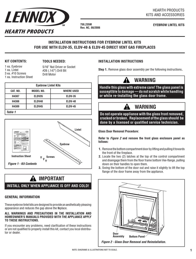
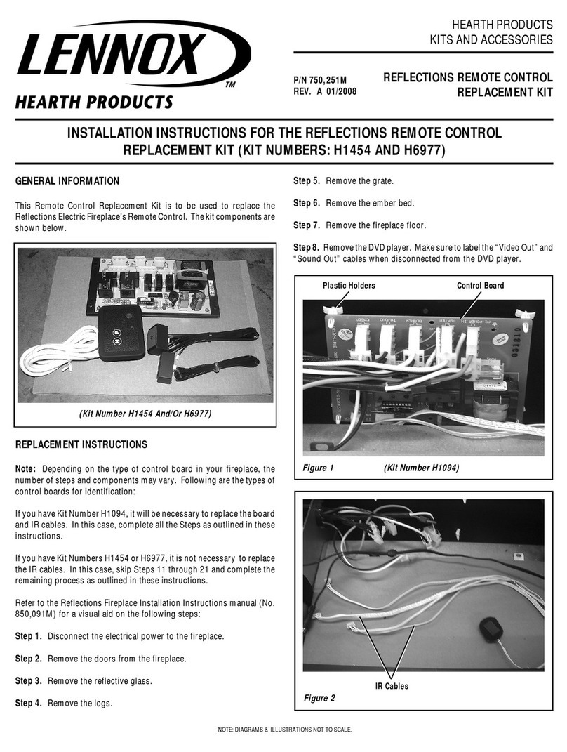
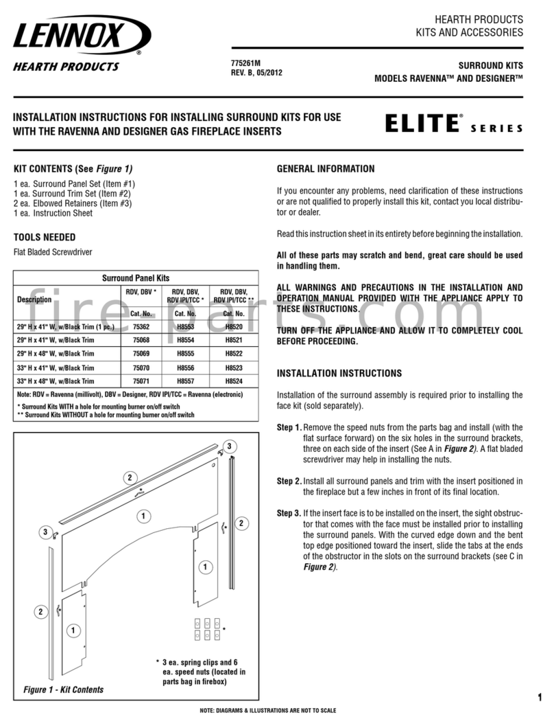
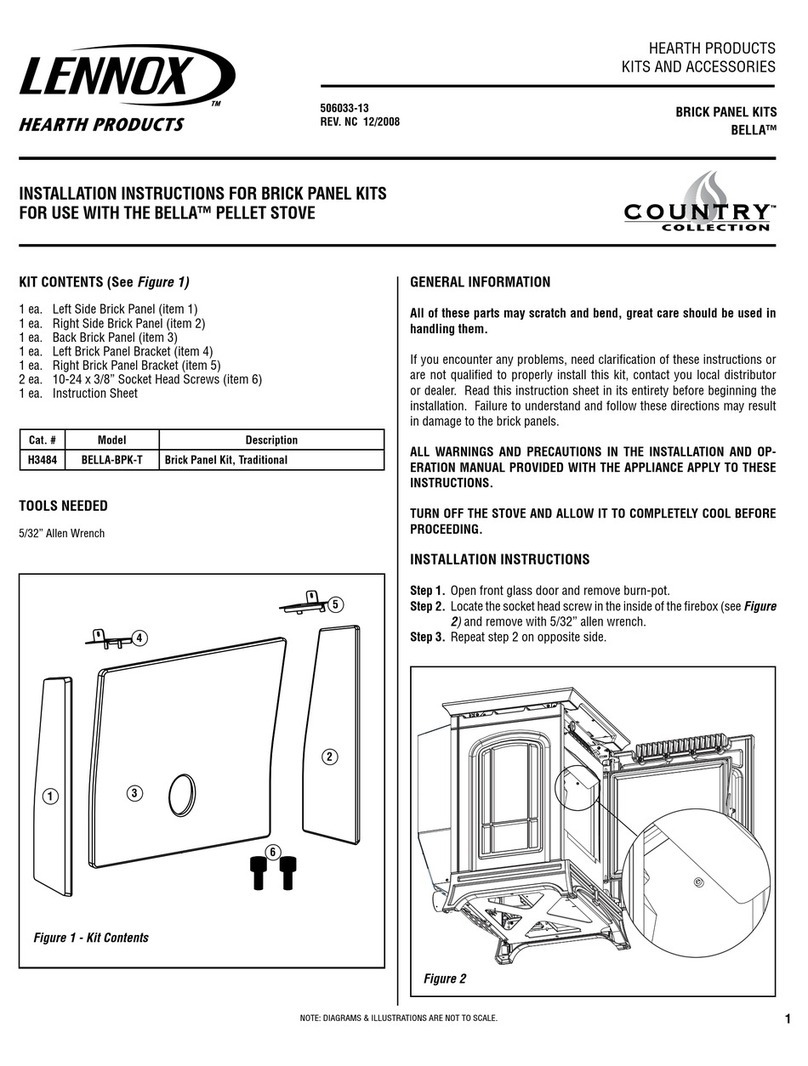
Lennox's Glass Door/End Panel Packaged Set, Models 38ACR and
38ACR-BB, are designed to be installed on the CR-3835R/L Series
fireplaces. These kits come complete with all of the required hardware
necessary to complete the task.
Please read and understand these instructions carefully before begin-
ning installation and operation. Do not attempt to alter or modify the
constructionoftheseglassdoorassembliesasitcouldcauseamalfunc-
tion or possible fire hazard.
The Models 38ACR and 38ACR-BB have been tested and listed by Omni
Test Laboratories, Inc.
PLEASE RETAIN THIS MANUAL FOR FUTURE REFERENCE.
GENERAL INFORMATION
Beforestartingtheinstallationoftheglassdoorsandendpanel,assure
thekitiscompleteandundamaged.Referto
Figure1
andtheinventory
list to identify all necessary parts.
INVENTORY LIST
A. (1) Top Channel (door) F. (1) Glass End Panel
B. (1) Bottom Channel (door) G. Door Panel Assembly LH
C. (1) Top Channel (panel) H. Door Panel Assembly RH
D. (1) Bottom Channel (panel) J. (2) Baffles
E.(1) Corner Post K. Hardware Kit (Including
Handles) Installation Instructions
Figure 1
END PANEL INSTALLATION STEPS
Step 1. Remove the screen rod covers from the front and corner
openings. Remove two angle retainers and replace screws.
Note: Units are shipped without covers installed.
Step2.Referto
Figure2
andremovethetoptwoouterscrewsandloosen
thebottom screws at leasttwo (2) turns. Remove cornershipping post,
if installed.
CAUTION: REMOVE THE PLASTIC PROTECTIVE COATING FROM ALL
BRASS PIECES BEFORE INSTALLATION.
J
B
A
H
G
E
C
D
F
K
US
NOTE: DIAGRAMS & ILLUSTRATIONS NOT TO SCALE
2
TOOLS REQUIRED
•Phillips screwdriver (small or medium)
Figure 2
Step3.Slidetheendpanelbottomchannelinto
position and tighten the end screws that were
previously loosened. Install the top track over
the middle screw and secure with the screws
removed and retained in Step 2.
Figure 4
BI-FOLD DOOR
INSTALLATION STEPS
Step1. Attachthepolished metalandwooden
handle assemblies to the lower door frames
(
Figure 5
). Use the No. 8-32 x 1/4 Philips pan
head screws and associated nuts provided in
the hardware kit. There is a single screw and
nut for use with each handle assembly. Slide
the nuts into the frame channel and insert the
screws through the handle brackets and then
into the nuts. Position the handle assemblies
approximately as shown on the front page of
thisdocumentandtightenthescrewstosecure
the handles in place.
Screw
(2 Places)
End Panel
Top Channel
Corner
Post
Outside
End Panel
Bottom Channel
Figure 8
Step4. Startingwitheithertherightorleftdoor
assembly.Engagethehingepinintotheholein
the clip within the top door channel. The roller
pin must be positioned within the upper door
guide track (
Figures 8 and 9
).
Pivot Pin Roller Pin
Figure 7
Figure 6
Remove
And Retain
Remove
And Retain
Loosen All Lower Screws
(At Least Two (2) Turns)
Do Not
Touch Loosen (At Least
Two (2) Turns)
Loosen (At Least
Two (2) Turns)
Remove
Shipping
Corner Post
Step 3. Refer to
Figures 2 and 7
and slide the
door bottom channel into position. Secure by
tighteningscrewspreviouslyloosenedthrough
theholesprovided on the top face ofthechan-
nel. Installthedoortopchanneloverthemiddle
screw and secure it in place with four screws,
twoscrewspreviouslyremovedandtwoscrews
previously loosened.
Step 2. Install two (2) baffles, one above the
otherwiththeblackNo.8-15x1/2"Phillipspan
head screws from the hardware kit (
Figure 6
).
Note: Thepinsontheglassendpanelrequire
repositioning when the door is fitted into an
opposing right or left hand opening. To shift
thepins,loosenthepinsusinga3/8"openend
wrenchandslidethepinsasrequiredalongthe
frame channel. Position the door squarely
withinthe opening equally gapped at the right
and left sides and secure the pins in place by
tightening with the wrench.
Figure 3
Step 4. Refer to
Figures3 and 4
and install the
cornerposttotheendsoftheendpaneltopand
bottom channels. Secure it in place with two
screws from the hardware kit.
Step 5. Insert the upper pins of the end panel
assembly into the holes in the top channel.
Swingthebottomportionoftheendpanelover
the bottom channel and insert the lower pins
into the bottom channel.
Figure 5
CAUTION: DO NOT OVER-TIGHTEN HANDLE
SCREWS.
NOTE: DIAGRAMS & ILLUSTRATIONS NOT TO SCALE 3
Figure 9
IMPORTANT
These glass doors utilize tempered glass
whichis designed foruse with high tempera-
tures but can unexpectedly shatter. DO NOT
SIT CLOSE TO THE GLASS.
Temperedglasswillbreakintosmallparticlesif
it should shatter unexpectedly. If the glass
breaks, particles of extremely hot glass could
be discharged into the surrounding environ-
ment,therebycreatinga riskofpersonalinjury
or fire. Observation of the above operating
precautions and instructions will reduce the
risk of personal injury or fire.
Extremetemperaturechangescancausebreak-
age — do not build a hot fire and close the
doors if the doors are cold.
Ifthetemperedglass panebecomes scratched
or chipped, it creates a weakness in the glass
whichcancausetheglasstobreakwhenheated.
Replace the pane of glass by contacting your
nearest LHP Distributor. For the name of your
nearest distributor contact:
LENNOX HEARTH PRODUCTS
1110 West Taft Avenue
Orange, CA 92865
CLEANING
NEVERCLEANTHEGLASSWHENTHEDOORS
ARE HOT. DO NOT USE AMMONIA OR ANY
AMMONIA BASED GLASS OR HOUSEHOLD
CLEANERTOCLEANTHEGLASSORTHEDOOR
FRAME.ANAMMONIABASEDCLEANERWILL
DAMAGE THE FINISH.
Remove dirt and grime from the doors using a
cleandampenedtowelfollowedbywiping with
a dry towel. To remove stubborn stains from
thedoors,useamildsoapsolutionandtowelto
gentlyscrubawaystain.Takecarenottoscratch
theglasssurface.Donotuseabrasivecleaners.
Figure 11
Step 6. Repeatthisprocedurefortheopposite
door assembly.
ADJUSTMENT FOR DOOR ALIGNMENT
The doors are properly adjusted when the top
doortrimisinastraight,levellineandthegap
between the doors is even at the top and
bottom.Ifadjustmentsarerequired,graspthe
door handle and loosen the lower door hinge
pin using a 3/8" open end wrench*. Slide the
door panel on the hinge pin until the gap
betweenthe upper door trim and upper frame
is even. Retighten the lower door hinge pin*.
Repeatthis procedure for the opposite door if
needed.
Hinge Pin Roller Pin
Upper Door
Guide Track
Pivot
Point
Bottom
Door
Channel
CAUTION: GLASS AND METAL FRAMES GET
HOT—ALWAYSUSEHANDLESTOOPENAND
CLOSE THE DOORS.
Figure 12
GENERAL OPERATING PRECAUTIONS
AND INSTRUCTIONS
CAUTION: THESE GLASS DOORS ARE
LISTED ONLY FOR USE WITH THE SUPE-
RIOR FIREPLACE OR APPLIANCE MODELS
SHOWN. USE ON ANY OTHER FIREPLACE
OR APPLIANCE MAY CONSTITUTE A PO-
TENTIAL FIRE HAZARD.
•Avoid building extremely large fires as the
tempered glass could become damaged.
•Usefireplace tools carefully to avoid striking
the glass.
•Keep wire mesh screens closed during fire-
place use.
•The fireplace flue damper must remain open
until fire is completely out.
•Assure wood and embers are well within the
confinesofthegrateareaandwellawayfrom
the glass doors.
•Keep glass doors closed at night when retir-
ingtominimizethelossofheatedroomairup
the vent.
CAUTION: THE CORNER FIREPLACE OR AP-
PLIANCESHOULDONLY BEOPERATEDWITH
THEBI-FOLDGLASSDOORSFULLYOPENOR
FULLY CLOSED (
FIGURE 12
).
Fully Open or
Fully Closed
End Panel
Step 5. Lift and swing the lower corner of the
door over the hole in the bottom door channel
andengagetheshorter hinge pin into this hole
(
Figures 10 and 11
).
Figure 10
*Note: Upper door hinge pins can also be
loosenedforadjustmentpurposes;however,it
is easier to loosen lower pins.
Lower Hinge Pin
WARNING: DO NOT BURN TRASH,
CONSTRUCTIONSCRAPS,RAILROAD
TIES, OR OTHER HIGHLY-FLAM-
MABLE MATERIAL IN THE FIRE-
PLACE. INTENSE HEAT CAN CAUSE
THEGLASSTOLOSESTRENGTHAND
RESILIENCEWHICHWILLRESULTIN
GLASS BREAKAGE.
NOTE: DIAGRAMS & ILLUSTRATIONS NOT TO SCALE
4
Printed in U.S.A. © 1999 by LENNOX HEARTH PRODUCTS
P/N 904665 REV. C 03/2008
The manufacturer reserves the right to make changes at any time, without notice, in design, materials, specifications, prices and also to discontinue colors, styles and products.
Consult your local distributor for fireplace code information.
1110 West Taft Avenue • Orange, CA 92865

This manual suits for next models

1

Other Lennox Fireplace Accessories manuals

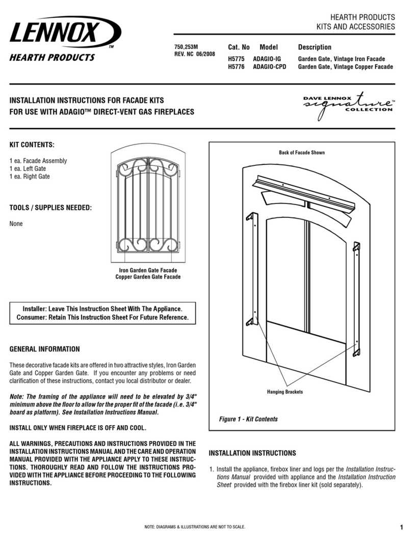
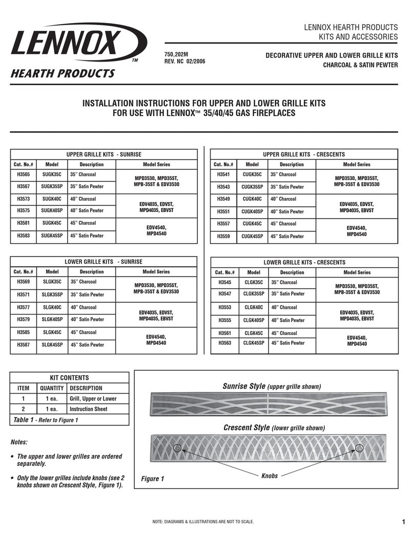
Lennox ADAGIO-IG User manual

Lennox

Lennox ADAGIO-IG User manual

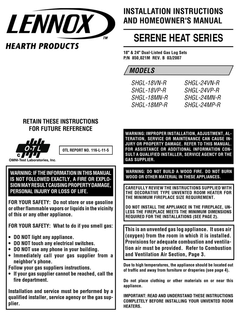
Lennox SHGL-18VN-R Assembly instructions

Lennox

Lennox SHGL-18VN-R Assembly instructions

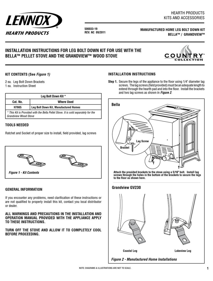
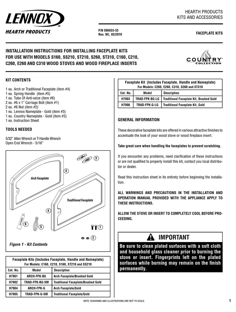
Lennox TRAD-FPK-BG-LG User manual

Lennox

Lennox TRAD-FPK-BG-LG User manual

Lennox BELLA-PK-TB User manual

Lennox

Lennox BELLA-PK-TB User manual

Lennox MPD3530 User manual

Lennox

Lennox MPD3530 User manual

Lennox H7665 User manual

Lennox

Lennox H7665 User manual

Lennox DVR-5000 Series User manual

Lennox

Lennox DVR-5000 Series User manual

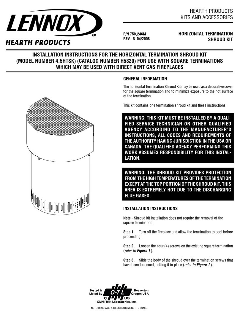
Lennox 4.5HTSK User manual

Lennox

Lennox 4.5HTSK User manual

Lennox BELLA-BPK-T User manual

Lennox

Lennox BELLA-BPK-T User manual

Lennox Elite series User manual

Lennox

Lennox Elite series User manual

Lennox TK3-36PB User manual

Lennox

Lennox TK3-36PB User manual

Lennox Elite series User manual

Lennox

Lennox Elite series User manual

Lennox Signature Shoreline User manual

Lennox

Lennox Signature Shoreline User manual

Lennox AKM-LSM User manual

Lennox

Lennox AKM-LSM User manual

Lennox H6977 User manual

Lennox

Lennox H6977 User manual

Lennox Eyebrow Lintel Kit ELDV-35 User manual

Lennox

Lennox Eyebrow Lintel Kit ELDV-35 User manual

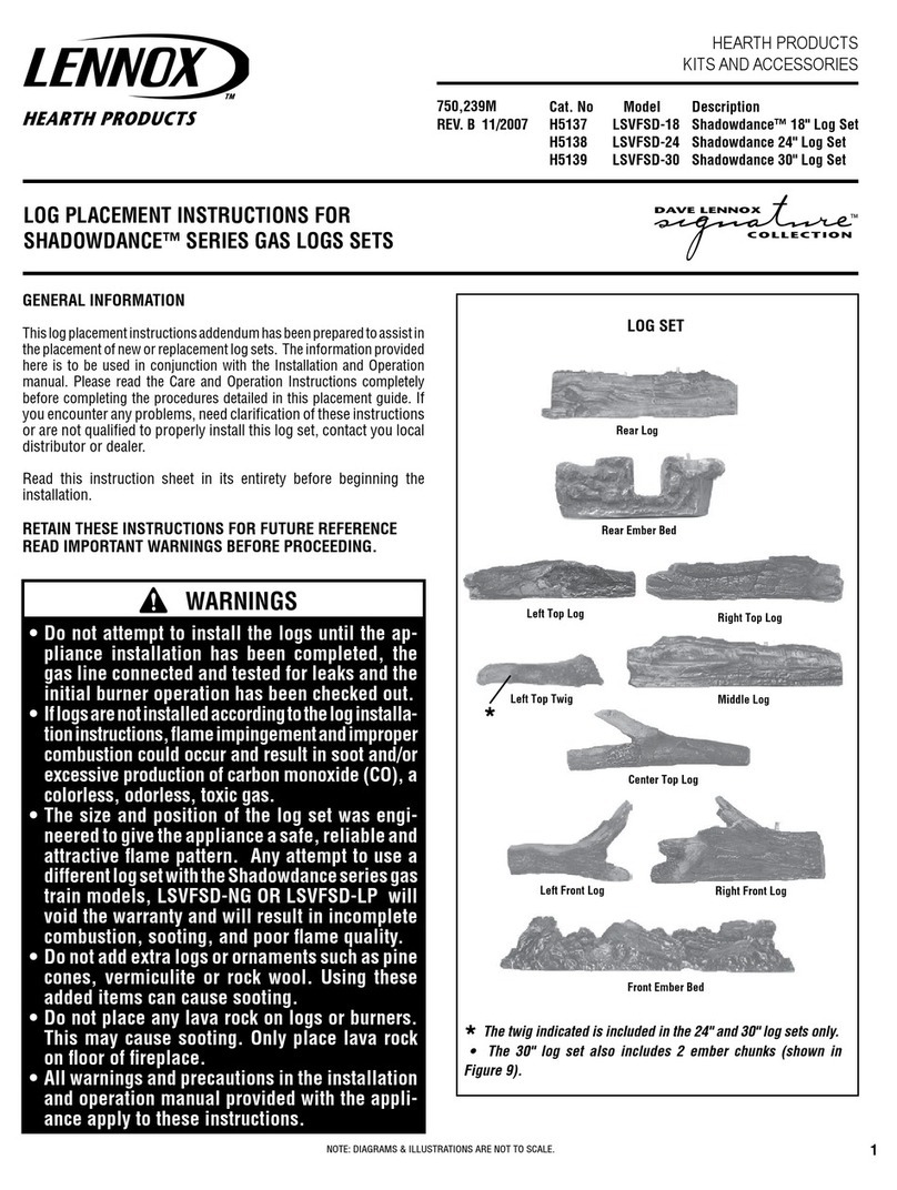
Lennox Shadowdance LSVFSD-30 User manual

Lennox

Lennox Shadowdance LSVFSD-30 User manual

Lennox WS-PED User manual

Lennox

Lennox WS-PED User manual

Popular Fireplace Accessories manuals by other brands

Heatmaster HFB-BBB installation instructions

Heatmaster

Heatmaster HFB-BBB installation instructions

Montigo Proflame 2 RX 300 NG Installation & maintenance manual

Montigo

Montigo Proflame 2 RX 300 NG Installation & maintenance manual

Napoleon HD35 instructions

Napoleon

Napoleon HD35 instructions

Outdoor Lifestyles ODCOUG-36SSL installation instructions

Outdoor Lifestyles

Outdoor Lifestyles ODCOUG-36SSL installation instructions

Napoleon LEGEND Series Assembly guide

Napoleon

Napoleon LEGEND Series Assembly guide

Valor PORTRAIT installation instructions

Valor

Valor PORTRAIT installation instructions

Valor LINEAR SERIES installation instructions

Valor

Valor LINEAR SERIES installation instructions

Valor Madrona installation manual

Valor

Valor Madrona installation manual

Napoleon NEFTK30BK-3828 installation instructions

Napoleon

Napoleon NEFTK30BK-3828 installation instructions

Lennox Hearth Products DPSS36 installation instructions

Lennox Hearth Products

Lennox Hearth Products DPSS36 installation instructions

Napoleon TMCSS installation instructions

Napoleon

Napoleon TMCSS installation instructions

Broyhill 2721FM-32-201 Assembly instructions

Broyhill

Broyhill 2721FM-32-201 Assembly instructions

Valor HeatShift LDK Series installation instructions

Valor

Valor HeatShift LDK Series installation instructions

Dimplex CDFI-BX1000 Assembly instructions

Dimplex

Dimplex CDFI-BX1000 Assembly instructions

Valor LT1 Series installation manual

Valor

Valor LT1 Series installation manual

Valor 614CVI user manual

Valor

Valor 614CVI user manual

Wolf Steel DBPEX36 installation instructions

Wolf Steel

Wolf Steel DBPEX36 installation instructions

kozy heat BAY-41-MV Installation and operation manual

kozy heat

kozy heat BAY-41-MV Installation and operation manual

manuals.online logo
manuals.online logoBrands
  • About & Mission
  • Contact us
  • Privacy Policy
  • Terms and Conditions

Copyright 2025 Manuals.Online. All Rights Reserved.