manuals.online logo
Brands
  1. Home
  2. •
  3. Brands
  4. •
  5. Let's Go Aero
  6. •
  7. Automobile Accessories
  8. •
  9. Let's Go Aero BikeWing-2 User manual

Let's Go Aero BikeWing-2 User manual

Page 1 of 9
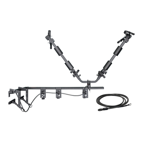
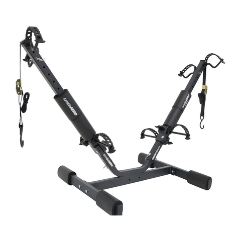
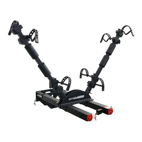
BikeWing®-2
Tilting Hitch V-Rack™ Carrier for Two Bikes
Part No. B01861
Revision Date: 12/12/19BW-B01861-121219Rev
ASSEMBLY, INSTALLATION, AND OPERATION INSTRUCTIONS
To register your product, visit the LetsGoAero.com/registration
For More Information & Accessories:
Visit our Website - www.LetsGoAero.com
For Technical Support & Product Questions:
Contact Us at 877-464-2376 or 719- 630-3800
Email: [email protected]
Let’s Go Aero, Inc. 4474 Barnes Road Colorado Springs, CO 80917, USA
Patent and trademark protected:
Patent Number 8,889,456; Patents Pending
Maximum load weight limit is 40 lbs per bicycle. Rack empty weight is 20 lbs.
For 1.25in & 2in Hitch Receivers
NOTICE: All Manual information is subject to change without notice. Revised editions
will be available for free download at LetsGoAero.com. Manual information is considered
factual until made obsolete by a revised version.
Follow this QR-Code or visit
LetsGoAero.com/manuals to check for an updated version:
Copyright© 2019, Lets Go Aero, Inc., All rights reserved.
PRODUCT MANUAL
A
B
C
D
E
F
G
H
J
K
L
M
N
O
P
Q
R
S
T
1
1
2
1
1
1
1
1
1
2
4
2
2
8
2
4
4
8
8
SHANK
2IN HITCH ADAPTER
6MM SOCKET HEAD BOLT
NOMOTION™ HITCH PIN
LOCK WASHER
FLAT WASHER
LARGE RETAINER CLIP
STEM
WIRE LOCK PIN
10mm BOLT
10mm FLAT WASHER
10mm NYLOCK NUT
RING PIN
CRADLE HOUSING
WING
UPPER WHEEL CRADLE
LOWER WHEEL CRADLE
RUBBER STRAP
SMALL RETAINER CLIP
QTY. DESCRIPTION
PARTS
Page 2 of 9
STEP 1: INSTALLATION (FOR 1.25IN HITCHES ONLY)
STEP 2:
1.25in Hitch Receiver 2in Hitch Receiver
FOR 1.25IN HITCH RECEIVERS
ONLY
Vehicles with 2in Hitches must
skip this step.
For vehicles with 1.25in hitches
unbolt the two 6mm Socket Head
Bolts [C] connecting the factory
installed Hitch Adapter [B] to
the end of the Shank [A] and
removed the Hitch Adapter. [Fg. 1]
Slide the end of the Shank [A] into the Hitch Receiver and align the pin holes. [Fg. 2 & 3]
[Fg. 1]
[Fg. 2] [Fg. 3]
A
A
A
D
G
E
F
A
B
B
C
STEP 3:
Slide the Lock Washer [E] and Flat
Washer [F] onto the NoMotion Pin [D] with
the Lock Washer positioned closest to the
hex head of the NoMotion Pin.
With the pin holes of the Shank [A] and
hitch receiver aligned, insert the NoMotion
Pin [D] with the attached Washers [E & F]
into the vehicle hitch receiver.
Secure the NoMotion Pin [D] with the
Large Retainer Clip [G]. [Fg. 4]
NOTE: For vehicles with 2in Hitch
Receivers, the NoMotion Pin must be
inserted from the side of the Shank
[A] where the Hitch Adapter [B] is the
thickest.
RECOMMENDED TOOL: 3/4” WRENCH
[Fg. 4]
Page 3 of 9
STEP 4:
STEP 5:
Remove the pre-attached Wire Lock Pin [J] and let is hang loose.
Slide the Stem [H] in-between the plates of the Shank [A] and align the holes vertically. [Fg. 5]
Using the bottom vertically aligned hole. Secure the Stem to the Shank using one (1) 10mm Bolt [K], two (2) 10mm Flat
Washers [L] and one (1) 10mm Nylock Nut [M] as shown. [Fg. 6]
STANDARD VEHICLE ONLY USE:
Install the Wire Lock Pin [J] into the top aligned hole of the
Shank and Stem to lock the tilt function. [Fg. 7]
RV & OFF ROAD USE:
In the same manor as Step 4, install one (1) 10mm Bolt
[K], two (2) 10mm Flat Washers [L] and one (1) 10mm
Nylock Nut [M] into the top aligned hole as shown.
Install the Wire Lock Pin [J] into the remaining hole to
prevent it from freely swinging. [Fg. 8]
RECOMMENDED TOOL: 15mm Wrench & 6mm Hex Tool
A
J
H
[Fg. 5]
A
A
K
L
M
L
A
AL
H
H
J
J
K
L
M
H
[Fg. 6]
[Fg. 8]
[Fg. 9]
ALWAYS SECURE THE STEM [H] WITH TWO 10mm
BOLTS AS SHOWN FOR RV & OFF ROAD USE.
WARNING:
Page 4 of 9
STEP 7:
STEP 6:
Install one Wing [P] onto
each side of the Stem.
Secure with Ring Pin [N].
[Fg. 13 & 14]
NOTE: The Ring Pin [N]
MUST always be inserted
through the hole on the
Stem [H] from above/
inside the Stem upright
as shown.
NOTE: You can use a
straight tool (such as a
Lower Wheel Cradle [R])
to tighten the Ring Pins
further if needed. H
N
P
H
P
[Fg. 13] [Fg. 14]
TIP!: The BikeWing carrier and mounted bicycles can be locked to the vehicle using a standard cable lock (not
included) by running a cable through the Ring Pins [N], the hehicle hitch and the mounted bicycles.
Using one (1) Wing [P], slide both foam
bumpers to the center of the Wing.
Turn the handles on each Cradle Housing O]
to loosen their grip.
Slide two (2) Cradle Housings [O] above the
foam bumpers and two (2) more Cradle
Housings below the foam bumpers. [Fg. 10,
11 & 12]
NOTE: The cylinders located on each Cradle
Housing [O] MUST rest along the
same sides as the connection hole located at
the bottom of the Wing [P].
NOTE: It is recommended to Position the
cylinders located on each Cradle Housing [O]
so that they alternate direction as shown.
Re-tighten each Cradle Housing [O] handle to
secure in place on the Wing [P].
Repeat this step for the second Wing [P].
CYLINDER
CONNECTION
HOLE
FOAM
BUMPERS
O
P
P
P
O
O
O
[Fg. 10] [Fg. 11] [Fg. 12]
Page 5 of 9
STEP 8:
STEP 9:
R
Q
Q
Slide the round end of one (1) Rubber Strap [S] onto
each Upper Wheel Cradle [Q] and Lower Wheel
Cradle [R]. [Fg. 13]
NOTE: Be sure to slide the Rubber Straps [S] all the
way onto the cradles so that it tightly rests over the
plastic coating of the Wheel Cradle [Q & R].
S
S
[Fg. 15]
T
P
OS
S
Insert two (2) Upper Wheel Cradles [Q] with
Rubber Straps [S] facing in opposite directions
into the two (2) Cradle Housing [O] installed
above the foam bumpers on each Wing [P] as
shown. [Fg. 16]
Secure each Upper Wheel Cradle [Q] with a
Retainer Clip [T].
[Fg. 16]
STEP 9:
Insert two (2) Lower Wheel Cradles [R] with Rubber Straps
[S] facing in opposite directions into the two (2) Cradle
Housing [O] installed below the foam bumpers on each
Wing [H]. [Fg. 17]
Secure each Lower Wheel Cradle [L] with a Retainer Clip
[N].
T
R
O
P
[Fg. 17]
Page 6 of 9
Operation: Bicycle Mounting
Hang bicycles by the tires on the Upper Wheel Cradles [Q] with the chain rings to the outside. [Fg. 18 & 19]
Adjust the Foam Bumpers located on the Wings [H] to protect the frame of the bicycle.
IMPORTANT: For two bicycles, position the bicycles facing in opposite directions (front-to-back/back-to-front) with the
chain ring to the outside.
Some adjustment of the Wheel Cradles may be necessary in order to accommodate both bicycles.
Secure by tensioning each Rubber Strap [S] over the top of each tire and engaging a strap hole over the end of the Upper
Wheel Cradle [Q] using the tightest hole available. [Fg. 20 & 21]
[Fg. 18] [Fg.19]
[Fg. 20]
[Fg. 21]
Q
Q
M
Page 7 of 9
Slide the Lower Wheel Cradle [R] to meet the
bottom/side of the bicycle tire.
Secure the Lower Wheel Cradle [R] using the
same technique as the Upper Wheel Cradles. [Fg.
22 & 23]
TIP: Pull the Rubber Straps [M] to the outside edge
of the outer edge Lower Cradle [R] to position
bicycles wheels
so the frame
of the bicycle
is pulled away
from the Wings
[H] for wheel
touch only
performance.
[Fg. 23]
Adjusting Position of Bicycles
To accommodate varying bike sizes, slide the cradle along the wings and re-tighten. [Fg. 24]
TIP: Lower Wheel Cradles [R] can be easily reversed while the bicycle is hangs from the Upper Wheel Cradles [M] to the
opposite side of the their housing for quick adjustability.
[Fg.23]
[Fg.24]
[Fg.22]
M
R
R
TIP: For standard vehicle use only, for faster mounting only one (1) Lower Wheel Cradle [R] is necessary on the
front tire to achieve full Zero-G stability.
[Fg.25]
Page 8 of 9
OPERATION: TILT
For loading and rear hatch access the BikeWing-2’s V-Base can be tilted to a ~50° angle.
VEHICLE MUST BE STATIONARY WHILE THE RACK IS TILTED - NOT FOR USE IN TRANSIT.
Begin by removing the Tilt Pin and Retainer Clip [Q] from the upper hole of the Tilt Bracket located on the Shank [A].
Insert the Wire Lock Pin [J] in the adjacent hole from the 10mm Bolt and secure with the Wire Lock Pin. Lower the Stem
[H] to REST ON TOP of the Wire Lock Pin. [Fg. 26 & 27]
[Fg.26] [Fg.26]
JJ
A
A
H
Keep bicycles away from hot exhaust.
Drive conservatively, especially over bumps.
Bicycles should never extend beyond sides of vehicle.
For best weight distribution, always load heaviest bicycles closest to vehicle hitch and lightest bicycles farther away.
Do not use Let’s Go Aero carriers and accessories for purposes other than which they were designed.
MAXIMUM WEIGHT CAPACITY LIMIT
The maximum load weight per bicycle is 40 lbs. Do not exceed this weight per bicycle. Failure to follow this guideline will
void the warranty.
The maximum overall weight limit is 40 lbs per bicycle plus the empty weight of the rack. This limit is always
subordinate to the maximum load recommended by the manufacturer of the vehicle itself. It is always the lower
maximum recommended load that applies. Do not exceed the load weight limit of the rack or the manufacturer’s
vehicle receiver hitch tongue weight rating. Consult your vehicle manual for your receiver hitch tongue weight rating.
Failure to follow these guidelines or the product’s instructions will void the warranty.
WARNING:
Make sure the NoMotion hitch pin is properly secured by tightening rmly with a wrench. Always check that all bolts
and connections are tight and fully secure. Make sure the bicycles are securely attached to the bicycle rack using all
required straps provided. Make sure additional care is taken for securing bicycles to rack for RV and trailer use as
instructed. Failure to follow proper installation and equipment checks before transit may result in damage to carrier,
proper, bodily injury, or death.
WARNING:
OPERATION GUIDELINES
Page 9 of 9
Car vehicle exhaust can cause a hazard. As a precaution, position bicycles clear of exhaust.
CAUTION:
If a Let’s Go Aero bike rack is found to have a defect in workmanship or material over the lifetime of the original purchaser, Let’s Go
Aero will repair or replace the defect free of charge. This warranty terminates if a purchaser transfers the product to any other person.
The warranty does not cover damage or wear which occurs as a result of day to day use or general wear and tear. No warranty is given
for defects caused by normal wear and tear, cosmetic rust, scratches, accidents, unlawful vehicle operation, or modication of, or any
types of repair of, a load carrier system other than those authorized by Let’s Go Aero.
No warranty is given for defects resulting from conditions beyond Let’s Go Aero’s control including, but not limited to, misuse, overload-
ing, or failure to assemble, mount or use the product in accordance with Let’s Go Aero’s written instructions or guidelines included with
the product or made available to the purchaser.
Subject to the limitations and exclusions described in this warranty, Let’s Go Aero will remedy defects in materials or workmanship by
repairing or replacing any parts diagnosed to be at issue without charge for parts or labor. In the event that a product is defective, the
purchaser should contact the Let’s Go Aero dealer from whom the product was purchased. If the dealer is not able to correct the defect,
the purchaser should contact Let’s Go Aero in writing to [email protected] or by phone at 877-464-237 or 719-630-3800.
In the event that a product needs to be returned to Let’s Go Aero, a Let’s Go Aero technician will provide the purchaser with the appro-
priate mailing address and any additional instructions. Proof of purchase in the form of an original purchase invoice or receipt, and a
detailed description of the defect must be provided. Please note that a Return Merchandise Authorization (RMA) from Let’s Go Aero is
required for any returns.
DISCLAIMER OF LIABILITY REPAIR OR REPLACEMENT OF A DEFECTIVE PRODUCT OR THE ISSUANCE OF A REFUND OR
CREDIT (AS DETERMINED BY LET’S GO AERO) IS A PURCHASER’S EXCLUSIVE REMEDY UNDER THIS WARRANTY. DAMAGE
TO A PURCHASER’S VEHICLE, CARGO AND/OR TO ANY OTHER PERSON OR PROPERTY IS EXCLUDED.
THIS WARRANTY IS EXPRESSLY MADE IN LIEU OF ANY AND ALL OTHER WARRANTIES, EXPRESS OR IMPLIED, INCLUDING
THE WARRANTIES OF MERCHANTABILITY AND FITNESS FOR A PARTICULAR PURPOSE.
LET’S GO AERO’S SOLE LIABILITY TO ANY PURCHASER IS LIMITED TO THE REMEDY SET FORTH ABOVE. IN NO EVENT WILL
LET’S GO AERO BE LIABLE FOR ANY LOST PROFITS, LOST SALES, OR FOR ANY CONSEQUENTIAL, DIRECT, INDIRECT, INCI-
DENTAL, SPECIAL, EXEMPLARY, OR PUNITIVE DAMAGES OR FOR ANY OTHER DAMAGES OF ANY KIND OR NATURE.
SOME STATES DO NOT ALLOW THE EXCLUSION OR LIMITATION OF INCIDENTAL OR CONSEQUENTIAL DAMAGES, SO THE
ABOVE LIMITATIONS MAY NOT BE APPLICABLE. THIS WARRANTY GIVES YOU SPECIFIC LEGAL RIGHTS, AND YOU MAY ALSO
HAVE OTHER RIGHTS WHICH VARY FROM STATE TO STATE.
LET’S GO AERO LIMITED LIFETIME WARRANTY

This manual suits for next models

1

Other Let's Go Aero Automobile Accessories manuals

Let's Go Aero VME-V4 User manual

Let's Go Aero

Let's Go Aero VME-V4 User manual

Let's Go Aero BLACK BOX Owner's manual

Let's Go Aero

Let's Go Aero BLACK BOX Owner's manual

Let's Go Aero HideOut Package H01564 User manual

Let's Go Aero

Let's Go Aero HideOut Package H01564 User manual

Let's Go Aero GearCage Ramp User manual

Let's Go Aero

Let's Go Aero GearCage Ramp User manual

Let's Go Aero HideOut Package H01564 User manual

Let's Go Aero

Let's Go Aero HideOut Package H01564 User manual

Let's Go Aero Fly Rod Adapter Kit User manual
Let's Go Aero

Let's Go Aero Fly Rod Adapter Kit User manual

Let's Go Aero B01809 User manual

Let's Go Aero

Let's Go Aero B01809 User manual

Let's Go Aero T01991 User manual

Let's Go Aero

Let's Go Aero T01991 User manual

Let's Go Aero Fork-IT H01793 Installation instructions

Let's Go Aero

Let's Go Aero Fork-IT H01793 Installation instructions

Let's Go Aero BlackBox PRO Installation instructions

Let's Go Aero

Let's Go Aero BlackBox PRO Installation instructions

Let's Go Aero Seal Skin Tonneau Cover Installation instructions

Let's Go Aero

Let's Go Aero Seal Skin Tonneau Cover Installation instructions

Let's Go Aero V-Lectric PRO Bicycle Carrier User manual

Let's Go Aero

Let's Go Aero V-Lectric PRO Bicycle Carrier User manual

Let's Go Aero Half Nelson User manual

Let's Go Aero

Let's Go Aero Half Nelson User manual

Let's Go Aero GearSpace HGK819 User manual

Let's Go Aero

Let's Go Aero GearSpace HGK819 User manual

Let's Go Aero LittleGiant Quick reference guide

Let's Go Aero

Let's Go Aero LittleGiant Quick reference guide

Let's Go Aero Three-Quarter Nelson User manual

Let's Go Aero

Let's Go Aero Three-Quarter Nelson User manual

Let's Go Aero GearCage SP4 Installation instructions

Let's Go Aero

Let's Go Aero GearCage SP4 Installation instructions

Let's Go Aero BikeTree B01618 User manual

Let's Go Aero

Let's Go Aero BikeTree B01618 User manual

Let's Go Aero GearDeck H00604 User manual

Let's Go Aero

Let's Go Aero GearDeck H00604 User manual

Let's Go Aero GearDeck 17 Installation instructions

Let's Go Aero

Let's Go Aero GearDeck 17 Installation instructions

Let's Go Aero BIGBOX User manual

Let's Go Aero

Let's Go Aero BIGBOX User manual

Let's Go Aero BLACK BOX User manual

Let's Go Aero

Let's Go Aero BLACK BOX User manual

Let's Go Aero V-Lectric B01175 User manual
Let's Go Aero

Let's Go Aero V-Lectric B01175 User manual

Let's Go Aero PegBoard B01588 Installation instructions
Let's Go Aero

Let's Go Aero PegBoard B01588 Installation instructions

Popular Automobile Accessories manuals by other brands

Metec 806265 Mounting instructions

Metec

Metec 806265 Mounting instructions

Aries 35-2000 installation manual

Aries

Aries 35-2000 installation manual

TAUBENREUTHER 16-9510 instruction manual

TAUBENREUTHER

TAUBENREUTHER 16-9510 instruction manual

Thule Sport G2 W150 instructions

Thule

Thule Sport G2 W150 instructions

Toyota RAV4 2011 Quick reference guide

Toyota

Toyota RAV4 2011 Quick reference guide

EUFAB 17026 operating instructions

EUFAB

EUFAB 17026 operating instructions

Whispbar K720W Fitting instructions

Whispbar

Whispbar K720W Fitting instructions

AUTO-BLiP 2006+ Honda s2000 user manual

AUTO-BLiP

AUTO-BLiP 2006+ Honda s2000 user manual

IMMI S4S Installation instruction

IMMI

IMMI S4S Installation instruction

Sirius Satellite Radio XM Sky Dock XVSAP1V1 quick start guide

Sirius Satellite Radio

Sirius Satellite Radio XM Sky Dock XVSAP1V1 quick start guide

Prorack K657 Fitting instructions

Prorack

Prorack K657 Fitting instructions

Whispbar K347W Fitting instructions

Whispbar

Whispbar K347W Fitting instructions

Whispbar K308W Fitting instructions

Whispbar

Whispbar K308W Fitting instructions

TAUBENREUTHER 16-5890 Installation instruction

TAUBENREUTHER

TAUBENREUTHER 16-5890 Installation instruction

Barricade LD1 manual

Barricade

Barricade LD1 manual

Soundoff Signal nFORCE LED Interior Lightbar instructions

Soundoff Signal

Soundoff Signal nFORCE LED Interior Lightbar instructions

Car-Interface r.LiNK CI-RL2-N900 manual

Car-Interface

Car-Interface r.LiNK CI-RL2-N900 manual

Rhino-Rack Zenith manual

Rhino-Rack

Rhino-Rack Zenith manual

manuals.online logo
manuals.online logoBrands
  • About & Mission
  • Contact us
  • Privacy Policy
  • Terms and Conditions

Copyright 2025 Manuals.Online. All Rights Reserved.