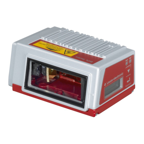
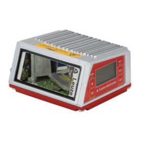
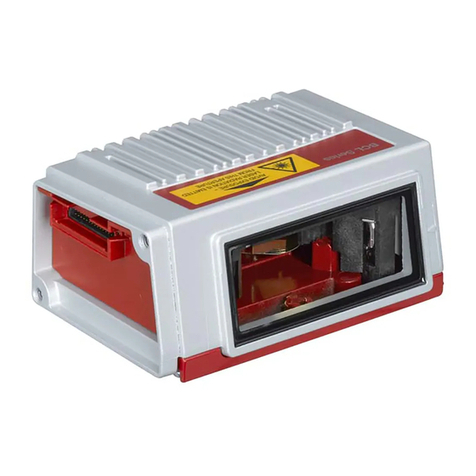
Leuze BCL 208i User manual

We reserve the right to make technical changes
EN • 2020-09-23 • 50144269
Original operating instructions
BCL 208i
Bar code reader

© 2020
Leuze electronic GmbH + Co. KG
In der Braike 1
73277 Owen / Germany
Phone: +49 7021 573-0
Fax: +49 7021 573-199
www.leuze.com
Leuze electronic GmbH + Co. KG BCL 208i 2

Table of contents
Leuze electronic GmbH + Co. KG BCL 208i 3
Table of contents
1 About this document ............................................................................................5
2 Safety .....................................................................................................................7
2.1 Intended use ...........................................................................................................................7
2.2 Foreseeable misuse ............................................................................................................... 7
2.3 Competent persons ................................................................................................................ 8
2.4 Disclaimer ............................................................................................................................... 8
2.5 Laser safety notices................................................................................................................8
3 Fast commissioning .............................................................................................9
3.1 Mounting ................................................................................................................................. 9
3.2 Selecting a mounting location.................................................................................................9
3.3 Electrical connection...............................................................................................................9
3.4 Preparatory settings..............................................................................................................10
3.4.1 Manually setting the IP address ........................................................................................10
3.4.2 Automatically setting the IP address .................................................................................11
3.4.3 Ethernet host communication............................................................................................11
3.5 Further settings.....................................................................................................................12
3.6 Starting the device ................................................................................................................12
3.7 Bar code reading .................................................................................................................. 13
4 Device description ..............................................................................................14
4.1 Device overview....................................................................................................................14
4.2 Performance characteristics .................................................................................................14
4.3 Device construction .............................................................................................................. 16
4.4 Display elements .................................................................................................................. 16
4.5 Reading techniques ..............................................................................................................18
4.5.1 Line scanner (single line) ..................................................................................................18
4.5.2 Raster scanner (raster line)...............................................................................................19
4.6 Fieldbus systems ..................................................................................................................19
4.6.1 Ethernet.............................................................................................................................19
4.6.2 Ethernet – star topology ....................................................................................................20
4.7 autoReflAct ........................................................................................................................... 20
4.8 Reference codes...................................................................................................................21
4.9 autoConfig ............................................................................................................................ 21
5 Mounting..............................................................................................................22
5.1 Transport and storage .......................................................................................................... 22
5.2 Mounting ...............................................................................................................................22
5.2.1 Mounting with M4 fastening screws ..................................................................................22
5.2.2 Mounting with BT56 or BT56-1 mounting device ............................................................22
5.2.3 Mounting with BT300-1 mounting device .........................................................................23
5.2.4 Mounting with the BT300W mounting bracket.................................................................23
5.3 Selecting a mounting location...............................................................................................23
5.4 Cleaning................................................................................................................................ 25
6 Electrical connection..........................................................................................26
6.1 PWR/SWIO (supply voltage, switching input and switching output) ..................................... 27
6.2 HOST (Ethernet, cable assignments) ................................................................................... 29
6.3 Ethernet topologies...............................................................................................................31
6.4 Cable lengths and shielding.................................................................................................. 31
Table of contents
Leuze electronic GmbH + Co. KG BCL 208i 4
7 Starting up the device – Leuze webConfig tool ...............................................32
7.1 System requirements............................................................................................................32
7.2 Start webConfig tool ............................................................................................................. 32
7.3 Short description of the webConfigtool ................................................................................33
7.3.1 CONFIGURATION menu ..................................................................................................33
8 Starting up the device - Configuration..............................................................35
8.1 Starting the device ................................................................................................................35
8.2 Setting configuration parameters..........................................................................................35
8.2.1 Manually setting the IP address ........................................................................................35
8.2.2 Automatically setting the IP address .................................................................................36
8.2.3 Ethernet host communication............................................................................................36
8.2.4 Address Link Label............................................................................................................37
8.3 Performing further settings ................................................................................................... 38
8.3.1 Decoding and processing the read data............................................................................38
8.3.2 Control of the decoding .....................................................................................................39
8.3.3 Control of the switching output ..........................................................................................39
8.3.4 Transfer configuration data ...............................................................................................40
9 Online commands...............................................................................................41
9.1 Overview of commands and parameters .............................................................................. 41
9.2 General online commands....................................................................................................41
9.3 Online commands for system control ................................................................................... 47
9.4 Online commands for configuration of switching inputs/outputs........................................... 48
9.5 Online commands for the parameter set operations............................................................. 49
10 Care, maintenance and disposal .......................................................................54
11 Diagnostics and troubleshooting......................................................................55
11.1 Error signaling via LED ......................................................................................................... 55
11.2 Interface error .......................................................................................................................55
12 Service and support ...........................................................................................56
13 Technical data .....................................................................................................57
13.1 General specifications .......................................................................................................... 57
13.2 Reading fields .......................................................................................................................59
13.2.1 Bar code characteristics ....................................................................................................59
13.2.2 Raster scanner ..................................................................................................................59
13.2.3 Reading field curves..........................................................................................................60
13.3 Dimensioned drawings ......................................................................................................... 62
14 Order guide and accessories.............................................................................63
14.1 Part number code .................................................................................................................63
14.2 Type overview....................................................................................................................... 63
14.3 Accessories – connection technology................................................................................... 63
14.4 Accessories – mounting systems ......................................................................................... 64
14.5 Accessories – Reflectors and reflective tapes ...................................................................... 64
15 EC Declaration of Conformity............................................................................65
16 Appendix..............................................................................................................66
16.1 ASCII character set............................................................................................................... 66
16.2 Bar code sample...................................................................................................................70

About this document
Leuze electronic GmbH + Co. KG BCL 208i 5
1 About this document
Used symbols and signal words
Tab.1.1: Warning symbols and signal words
Symbol indicating dangers to persons
Symbol indicating possible property damage
NOTE Signal word for property damage
Indicates dangers that may result in property damage if the measures for dan-
ger avoidance are not followed.
CAUTION Signal word for minor injuries
Indicates dangers that may result in minor injury if the measures for danger
avoidance are not followed.
WARNING Signal word for serious injury
Indicates dangers that may result in severe or fatal injury if the measures for
danger avoidance are not followed.
DANGER Signal word for life-threatening danger
Indicates dangers with which serious or fatal injury is imminent if the measures
for danger avoidance are not followed.
Tab.1.2: Other symbols
Symbol for tips
Text passages with this symbol provide you with further information.
Symbol for action steps
Text passages with this symbol instruct you to perform actions.
Symbol for action results
Text passages with this symbol describe the result of the preceding action.

About this document
Leuze electronic GmbH + Co. KG BCL 208i 6
Terms and abbreviations
Tab.1.3: Terms and abbreviations
AutoConfig Function for easily configuring a code type or number of digits
AutoReflAct Function for activation without additional sensors (Automatic Reflector Activa-
tion)
BCL Bar code reader
CRT Code reconstruction technology
EMC Electromagnetic compatibility
EN European standard
FE Functional earth
IP address Network address, which is based on the Internet Protocol (IP)
MAC address Media Access Control Address; hardware address of a device in the network
PELV Protective Extra-Low Voltage; protective extra-low voltage with reliable discon-
nection
PLC Programmable Logic Controller
SWI1 Digital switching input (Switching Input)
SWO2 Digital switching output (Switching Output)
TCP/IP Transmission Control Protocol/Internet Protocol; Internet protocol family
UDP Network data protocol (User Datagram Protocol)
UL Underwriters Laboratories

Safety
Leuze electronic GmbH + Co. KG BCL 208i 7
2 Safety
The barcode readers of the BCL200iseries were developed, manufactured and tested in accordance with
the applicable safety standards. They correspond to the state of the art.
2.1 Intended use
Barcode readers of the BCL200i series are conceived as stationary, high-speed scanners with integrated
decoders for all current barcodes used for automatic object detection.
Areas of application
The bar code readers of the BCL200i series are especially designed for the following areas of application:
• Storage and conveying technologies, in particular for object identification on fast-moving conveyor belts
• Pallet transport systems
• Automobile sector
CAUTION
Observe intended use!
The protection of personnel and the device cannot be guaranteed if the device is operated in a
manner not complying with its intended use.
ÄOnly operate the device in accordance with its intended use.
ÄLeuzeelectronicGmbH+Co.KG is not liable for damages caused by improper use.
ÄRead these operating instructions before commissioning the device. Knowledge of the oper-
ating instructions is an element of proper use.
NOTICE
Comply with conditions and regulations!
ÄObserve the locally applicable legal regulations and the rules of the employer's liability insur-
ance association.
2.2 Foreseeable misuse
Any use other than that defined under "Intended use" or which goes beyond that use is considered im-
proper use.
In particular, use of the device is not permitted in the following cases:
• in rooms with explosive atmospheres
• in circuits which are relevant to safety
• for medical purposes
NOTICE
Do not modify or otherwise interfere with the device!
ÄDo not carry out modifications or otherwise interfere with the device. The device must not be
tampered with and must not be changed in any way.
ÄThe device must not be opened. There are no user-serviceable parts inside.
ÄRepairs must only be performed by Leuze electronic GmbH + Co. KG.

Safety
Leuze electronic GmbH + Co. KG BCL 208i 8
2.3 Competent persons
Connection, mounting, commissioning and adjustment of the device must only be carried out by competent
persons.
Prerequisites for competent persons:
• They have a suitable technical education.
• They are familiar with the rules and regulations for occupational safety and safety at work.
• They are familiar with the operating instructions for the device.
• They have been instructed by the responsible person on the mounting and operation of the device.
Certified electricians
Electrical work must be carried out by a certified electrician.
Due to their technical training, knowledge and experience as well as their familiarity with relevant standards
and regulations, certified electricians are able to perform work on electrical systems and independently de-
tect possible dangers.
In Germany, certified electricians must fulfill the requirements of accident-prevention regulations DGUV
(German Social Accident Insurance) provision 3 (e.g. electrician foreman). In other countries, there are re-
spective regulations that must be observed.
2.4 Disclaimer
LeuzeelectronicGmbH+Co.KG is not liable in the following cases:
• The device is not being used properly.
• Reasonably foreseeable misuse is not taken into account.
• Mounting and electrical connection are not properly performed.
• Changes (e.g., constructional) are made to the device.
2.5 Laser safety notices
ATTENTION
LASER RADIATION – CLASS 1 LASER PRODUCT
The device satisfies the requirements of IEC/EN 60825-1:2014 safety regulations for a product
of laser class1 and complies with 21 CFR 1040.10 except for conformance with IEC 60825-1
Ed. 3., as described in Laser Notice No. 56, dated May 8, 2019.
ÄObserve the applicable statutory and local laser protection regulations.
ÄThe device must not be tampered with and must not be changed in any way.
There are no user-serviceable parts inside the device.
Repairs must only be performed by Leuze electronic GmbH + Co. KG.
CAUTION
Laser radiation
Opening the device can lead to dangerous exposure to radiation.

Fast commissioning
Leuze electronic GmbH + Co. KG BCL 208i 9
3 Fast commissioning
Below you will find a short description for the initial commissioning of the BCL208i. Detailed explanations
for all listed points can be found throughout these operating instructions.
3.1 Mounting
The bar code reader can be mounted in the following ways:
• Mounting with four M4x5 screws on the rear side of the housing.
• Mounting with mounting devices on the fastening groove on one side of the housing.
3.2 Selecting a mounting location
In order to select the right mounting location, several factors must be considered:
• Size, orientation, and position tolerance of the bar codes on the objects to be scanned.
• The reading field of the bar code reader in relation to the bar code module width.
• The resulting minimum and maximum reading distance from the respective reading field with the re-
spective module width (see chapter 13.2 "Reading fields").
• alignment of the bar code reader for avoiding reflections.
• Distance between bar code reader and host system with respect to the interface.
• The correct time for data output. The bar code reader should be positioned in such a way that, taking
into consideration the time required for data processing and the conveyor belt speed, there is sufficient
time to e.g. initiate sorting operations on the basis of the read data.
• The display elements such as LEDs should be highly visible.
• For configuring and commissioning with the webConfig tool, the HOST interface should be easily ac-
cessible.
For further information, see see chapter 5 "Mounting" and see chapter 6 "Electrical connection".
The best read results are obtained if the following prerequisites are fulfilled:
• The reading distance lies in the middle area of the reading field.
• There is no direct sunlight and protect against ambient light effects.
• The bar code labels are of good print quality and have good contrast ratios.
• You are not using high-glossy labels.
• The bar code is moved past with an angle of inclination of ±10°…15° to vertical.
NOTICE
Avoid direct reflection of the laser beam!
The beam on the bar code reader is emitted at 105° to the housing base. An angle of incidence
of 15° of the laser to the label has already been integrated in the deflecting mirror so that the bar
code reader can be installed parallel to the bar code (rear housing wall).
3.3 Electrical connection
The bar code reader is equipped with two connection cables, each with an M12 connector.
• PWR/SWIO: M12 connection for supply voltage and switching input/output, 5-pin, A-coded, cable
length 0.9m (unshielded)
• HOST: M12 connection for Ethernet, 4-pin, D-coded, cable length 0.7m (shielded)

Fast commissioning
Leuze electronic GmbH + Co. KG BCL 208i 10
12
2
3
1
4
5
1
32
4
1 PWR/SWIO
2 HOST
1 PWR/SWIO, M12 connector, 5-pin, A-coded
2 HOST, M12 socket, 4-pin, D-coded
Fig.3.1: Electrical connections
NOTICE
The shielding is connected using the M12 connector of the Ethernet cable.
Details on the connectors see chapter 6 "Electrical connection".
3.4 Preparatory settings
ÄConnect the +18…30 VDC supply voltage (typically +24VDC).
ðThe bar code reader starts up.
First, you must now set the communication parameters of the BCL208i. Make the necessary settings via
the webConfig tool, see chapter 8 "Starting up the device - Configuration".
3.4.1
Manually setting the IP address
Set the IP manually if your system does not include a DHCP server or if the IP addresses of the devices
are to be set permanently.
ÄHave the network administrator specify the data for IP address, net mask and gateway address of the
BCL208i.
ÄSet the values on the BCL208i.
In the webConfig tool:
Configuration > Communication > Ethernet interface
NOTICE
ÄAfter making the setting via the webConfig tool, restart the BCL208i.
ðThe set IP address is only accepted and active after a restart.

Fast commissioning
Leuze electronic GmbH + Co. KG BCL 208i 11
3.4.2
Automatically setting the IP address
Set the IP address automatically if a DHCP server assigns the IP addresses in the system.
ÄActivate the DHCP Client mode in the BCL208i.
In the webConfig tool:
Configuration > Communication > Ethernet interface
ÄActivate the DHCP=ON setting there.
3.4.3
Ethernet host communication
You can configure the connections to an external host system via the Ethernet host communication.
You can use both the UDP protocol as well as the TCP/IP protocol – in either client or in server mode. Both
protocols can be activated simultaneously and used in parallel.
• The connection-free UDP protocol is used primarily to transfer process data to the host (monitor opera-
tion).
• The connection-oriented TCP/IP protocol can also be used to transfer commands from the host to the
device. With this connection, the data is backed up by the TCP/IP protocol itself.
• If you would like to use the TCP/IP protocol, you must also define whether the device is to operate as a
TCP client or as a TCP server.
UDP
The device requires from the user the IP address and the port number of the communication partner. In the
same way, the host system (PC/control) also requires the set IP address of the device and the selected
port number. By assigning these parameters, a socket is formed via which the data can be sent and re-
ceived.
ÄActivate the UDP protocol.
ÄSet the following values:
ðIP address of the communication partner
ðPort number of the communication partner
The corresponding adjustment options can be found in the webConfig tool:
Configuration > Control > Host > Ethernet > UDP
TCP/IP
ÄActivate the TCP/IP protocol.
ÄSet the TCP/IP mode of the device.
ðIn TCP client mode, the device actively establishes the connection to the superior host system, e.g.,
PC/control as server. The device requires from the user the IP address of the server (host system)
and the port number on which the server (host system) accepts a connection. In this case, the de-
vice determines when and with whom a connection is established.
ðIn TCP server mode, the superior host system (PC/control) actively establishes the connection and
the connected device waits for the connection to be set up.
The TCP/IP stack must be informed by the user as to the local port of the device (port number) on
which connection requests from a client application (host system) are to be received.
If there is a connection request and a connection is established by the superior host system (PC/
control as client), the device – in server mode – accepts the connection. Data can then be sent and
received.
ÄWith a device as TCP client, set the following values:
ðIP address of the TCP server, normally the IP address of the control or the host computer
ðPort number of the TCP server
ðTimeout for the wait time for an answer from the server
ðRepetition time for renewed communication attempt following a timeout
ÄWith a device as TCP server, set the following values:
ðPort number for the communication of the device with the TCP clients
The corresponding adjustment options can be found in the webConfig tool:
Configuration > Control > Host > Ethernet > TCP/IP

Fast commissioning
Leuze electronic GmbH + Co. KG BCL 208i 12
3.5 Further settings
Carry out further settings, such as the control of the decoding and processing of the read data and the con-
figuration of the connected switching inputs and outputs.
Decoding and processing the read data
ÄDefine at least one code type with the desired settings.
In the webConfig tool:
Configuration > Decoder
Control of the decoding
Configure the connected switching input according to your requirements.
ÄConfigure the switching behavior.
In the webConfig tool:
Configuration > Device > Switching inputs/outputs
Control of the switching output
Configure the connected switching output according to your requirements.
ÄConfigure the switching behavior.
In the webConfig tool:
Configuration > Device > Switching inputs/outputs
3.6 Starting the device
ÄConnect the +18…30 VDC supply voltage (typically +24VDC).
ðThe BCL208i starts up, the PWR, NET and LINK LEDs indicate the operating state.
Tab.3.1: Display of operating state
LED Color State Description
PWR Green Flashing Device ok, initialization
Continuous light Power On, device OK
Briefly off - on Good read, reading successful
Green - red Green off – briefly
red – green on
No Read, reading not successful
Yellow Continuous light Service mode
Red Flashing Warning
Continuous light Error, device error
NET Green Flashing Initialization
Continuous light Network mode ok
Red Flashing Communication error
Continuous light Network error
LINK Green Continuous light Ethernet connected (LINK)
Yellow Flashing Data communication (ACT)
During the initialization phase (power on), the laser is switched on for approx. 2seconds. A configuration
code can be read in during this time.

Fast commissioning
Leuze electronic GmbH + Co. KG BCL 208i 13
NOTICE
Setting the IP address to the Leuze default address
By reading in the configuration code during the initialization phase, the IP address and the sub-
net mask are set to the Leuze default.
IP address: 192.168.60.101
Subnet mask: 255.255.255.0
192.168.060.101
Operating the bar code reader
After connecting a supply voltage of +18…30VDC to the switching input, a read process is activated. In
the standard setting, all common code types for decoding are released. Only the 2/5Interleaved code type
is limited to 10 digits of code content.
If a code is moved through the reading field, the code content is decoded and forwarded to the superior
system (PLC/PC) via Ethernet.
3.7 Bar code reading
ÄTest the device with the following bar code in format 2/5 Interleaved. The bar code module here is 0.5.
Modul 0,5
6677889900
The PWR LED goes off briefly and then turns green again. Simultaneously, the read information is for-
warded to the superior system (PLC/PC) via the Ethernet.
ÄCheck the incoming data of the bar code information.
Alternatively, you can use a switching input for read activation (switching signal of a photoelectric sensor or
24 V DC switching signal).

Device description
Leuze electronic GmbH + Co. KG BCL 208i 14
4 Device description
4.1 Device overview
Barcode readers of the BCL200i series are high-speed scanners with integrated decoder for all commonly
used barcodes, e.g. 2/5Interleaved, Code39, Code128, EAN8/13 etc., as well as codes from the
GS1DataBar family.
Bar code readers of the BCL200i series are available in various models as line/raster scanners with de-
flecting mirror.
The interfaces integrated in the various device models offer an optimum connection to the superior host
system:
• Ethernet TCP/IP UDP
• Ethernet/IP
• PROFINETIO
4.2 Performance characteristics
• Integrated fieldbus connectivity, Plug-and-Play fieldbus coupling and easy networking
• Numerous interface variants facilitate connection to the superior systems
• Ethernet
• Integrated code reconstruction technology (CRT) enables the identification of soiled or damaged bar
codes
• Maximum depth of field and reading distances from 40mm to 255mm
• Large optical opening angle and, thus, large reading field width
• High scanning rate with 1000scans/s for fast reading tasks
• Adjustment of all device parameters with a web browser
• Easy alignment and diagnostics functions
• Two freely programmable switching inputs/outputs for the activation or signaling of states
• Automatic monitoring of the read quality with autoControl
• Automatic recognition and setting of the bar code type using autoConfig
• Reference code comparison
• Heavy-duty housing of degree of protection IP65
NOTICE
Information on technical data and characteristics: see chapter 13 "Technical data"
Integrated fieldbus connectivity
The integrated fieldbus connectivity contained in the bar code readers of the BCL200i series facilitates the
use of identification systems which function without connection unit or gateways. The integrated fieldbus in-
terface considerably simplifies handling. The Plug-and-Play concept enables easy networking and very
simple commissioning: Directly connect the respective fieldbus and all configuration is performed with no
additional software.
CRT decoder
For decoding bar codes, the bar code readers of the BCL200i series make available the proven CRT de-
coder with code reconstruction technology.
The proven code reconstruction technology (CRT) enables bar code readers of the BCL200i series to read
bar codes with a small bar height, as well as bar codes with a damaged or soiled print image.
With the aid of the CRT decoder, bar codes can also be read without problem in other demanding situa-
tions, such as with a large tilt angle (azimuth angle or even angle of rotation).

Device description
Leuze electronic GmbH + Co. KG BCL 208i 15
Fig.4.1: Possible bar code orientation
Configuration
Configuration of the BCL208i usually takes place via the HOST interface using the integrated webConfig
tool. Alternatively, the bar code readers can be configured via the host/service interface using configuration
commands.
The bar code reader needs a suitable activation to start a read process as soon as an object is in the read-
ing field. This opens a time window ("reading gate") in the bar code reader for the read process during
which the bar code reader has time to detect and decode a bar code.
In the basic setting, triggering takes place through an external reading cycle signal. Alternative activation
options include online commands via the host interface and the autoReflAct function.
Through the read operation, the bar code reader collects additional useful pieces of data for diagnostics
which can also be transmitted to the host. The quality of the read operation can be inspected using the
alignment mode which is integrated in the webConfig tool.

Device description
Leuze electronic GmbH + Co. KG BCL 208i 16
4.3 Device construction
1
2
3
4
5
1 Reading window
2 Indicator LEDs
3 4 mounting threads on the rear of the device
4 Connection cable
5 Dovetail mounting
Fig.4.2: Device construction BCL200i – Line scanner with deflecting mirror
4.4 Display elements
Located on the front side of the housing are three multicolor indicator LEDs: PWR, NET, LINK.
Fig.4.3: LED indicators

Device description
Leuze electronic GmbH + Co. KG BCL 208i 17
PWR LED
Tab.4.1: PWR indicators
Color State Description
--- OFF Device off
No supply voltage
Green Flashing Device ok
• Initialization phase
• Bar code reading not possible
• Supply voltage applied
• Self test running
Continuous light Device ok
• Bar code reading possible
• Self test successfully finished
• Device monitoring active
Briefly off - on Good Read
• Bar code reading successful
Green briefly off –
briefly red – green on
No read
• Bar code reading not successful
Orange Continuous light Service mode
• Bar code reading possible
• No data on the host interface
Red Flashing Device ok, warning set
• Bar code reading possible
• Temporary operating fault
Continuous light Device error/parameter enable
• Bar code reading not possible
NET LED
Tab.4.2: NET indicators
Color State Description
--- OFF No supply voltage
• No communication possible
• Ethernet protocols not released
Green Flashing Initialization of the device
Establishing communication
Continuous light Operation ok
• Network mode ok
• Connection and communication to Host established
Red Flashing Communication error
• Temporary connection error
• If DHCP is active, no address could be obtained
Continuous light Network error
• No connection established
• No communication possible

Device description
Leuze electronic GmbH + Co. KG BCL 208i 18
LINK LED
Tab.4.3: LINK indicators
Color State Description
Green Continuous light Ethernet connected (LINK)
Yellow Flashing Data communication (ACT)
4.5 Reading techniques
4.5.1
Line scanner (single line)
The scan line scans the label. Due to the optical opening angle, the reading field width is dependent on the
read distance. Through the movement of the object, the entire bar code is automatically transported
through the scan line.
The integrated code reconstruction technology permits twisting of the bar code (tilt angle) within certain lim-
its. These are dependent on the transport speed, the scanning rate of the scanner and the bar code proper-
ties.
Areas of application of the line scanner
• With the bars of the bar code arranged lengthwise with respect to the conveying direction ("ladder ar-
rangement")
• With bar codes having very short bar lengths
• When the ladder code is turned out of the vertical position (tilt angle)
Fig.4.4: Deflection principle for the line scanner

Device description
Leuze electronic GmbH + Co. KG BCL 208i 19
4.5.2
Raster scanner (raster line)
Multiple scan lines scan the label. Due to the optical opening angle, the reading field width is dependent on
the read distance. Provided the code is located in the reading field, it can be read during standstill. If the
code moves through the reading field, it is scanned by multiple scan lines.
The integrated code reconstruction technology permits twisting of the bar code (tilt angle) within certain lim-
its. These are dependent on the transport speed, the scanning rate of the scanner and the bar code proper-
ties. In most cases, everywhere a line scanner is used, a raster scanner can be used.
Areas of application of the raster scanner
• With the bars of the bar code arranged perpendicular with respect to the conveying direction ("picket
fence arrangement")
• With bar codes with low height displacement
• With very glossy bar codes
NOTICE
There may not be two or more bar codes in the raster detection range simultaneously.
Fig.4.5: Deflection principle for the raster scanner
4.6 Fieldbus systems
Various product variants of the BCL200i series are available for connecting to different fieldbus systems
such as PROFINET, Ethernet, and EtherNet/IP.
4.6.1
Ethernet
The BCL208i is designed as an Ethernet device (acc. to IEEE 802.3) with a standard baud rate of
10/100Mbit. On delivery, each BCL208i comes with a unique MAC-ID; this ID cannot be changed.
The BCL208i automatically supports the transmission rates of 10Mbit/s (10BaseT) and 100Mbit/s
(100BaseTX), as well as auto-negotiation and auto-crossover.

Device description
Leuze electronic GmbH + Co. KG BCL 208i 20
The BCL208i features multiple M12 connectors / sockets for the electrical connection of the supply volt-
age, the interface and the switching inputs and outputs. For further information on electrical connection,
see chapter 6 "Electrical connection".
The BCL208i supports further protocols and services for communication:
• TCP / IP (client/server)
• UDP
• DHCP
• Telnet
• HTTP
• ARP
• PING
For communication with the superior host system, the corresponding TCP/IP protocol (client/server mode)
or UDP must be selected.
Further information on commissioning: see chapter 7 "Starting up the device – Leuze webConfig tool".
4.6.2
Ethernet – star topology
The BCL208i can be operated as a single device (stand-alone) with an individual IP address in a star
topology. The IP address can either be set permanently via webConfigtool or assigned dynamically via a
DHCP server.
1
2
3
4
1 Ethernet switch
2 Bar code reader of the BCL200i series
3 Other network participants
4 Host interface - PC/control
Fig.4.6: Ethernet in a star topology
4.7 autoReflAct
autoReflAct stands for automatic Reflector Activation and permits an activation without additional sensors.
This is achieved by directing the scanner with reduced scanning beam towards a reflector mounted behind
the conveyor path.
NOTICE
Suitable reflectors are available, see chapter 14.5 "Accessories – Reflectors and reflective
tapes".
This manual suits for next models
4
Table of contents
Other Leuze Barcode Reader manuals

Leuze
Leuze BCL 300i User manual

Leuze
Leuze BCL604i User manual

Leuze
Leuze BPS 348i User manual

Leuze
Leuze BCL 92 User manual

Leuze
Leuze DCR 55 User manual

Leuze
Leuze BCL 648i User manual

Leuze
Leuze BCL 900i User manual

Leuze
Leuze BCL 900i User manual

Leuze
Leuze BPS 34 User manual

Leuze
Leuze HS 6578 User manual

Leuze
Leuze BPS 3048i User manual

Leuze
Leuze DCR 258i User manual

Leuze
Leuze BCL 40 Parts list manual

Leuze
Leuze BCL 92 User manual

Leuze
Leuze CR 100 User manual

Leuze
Leuze IT 6320 DPM Setup guide

Leuze
Leuze HS 6508 User manual

Leuze
Leuze BCL34 Parts list manual

Leuze
Leuze BPS 3007i User manual

Leuze
Leuze IT 3800g User manual