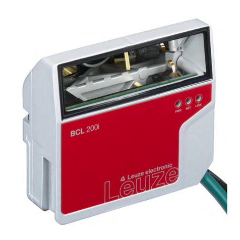
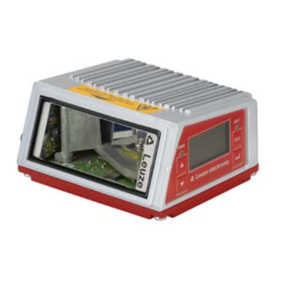
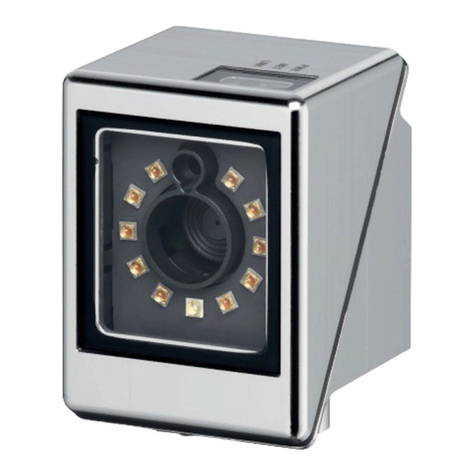
Leuze BCL 308i User manual

BCL 308
i
Bar code readers
Original operating instructions
EN • 2021-05-26 • 50117117
We reserve the right to make technical changes

Leuze electronic GmbH + Co. KG BCL 308
i
© 2021
Leuze electronic GmbH & Co. KG
In der Braike 1
D-73277 Owen / Germany
Phone: +49 7021 573-0
Fax: +49 7021 573-199
http://www.leuze.com

Leuze electronic GmbH + Co. KG BCL 308
i
1
1 General information . . . . . . . . . . . . . . . . . . . . . . . . . . . . . . . . . . . . . . . . . . . . . . . . . . . 7
1.1 Explanation of symbols . . . . . . . . . . . . . . . . . . . . . . . . . . . . . . . . . . . . . . . . . . . . . . . . . . . . . . . . . 7
1.2 Declaration of Conformity . . . . . . . . . . . . . . . . . . . . . . . . . . . . . . . . . . . . . . . . . . . . . . . . . . . . . . . 7
2 Safety . . . . . . . . . . . . . . . . . . . . . . . . . . . . . . . . . . . . . . . . . . . . . . . . . . . . . . . . . . . . . . 8
2.1 Intended use . . . . . . . . . . . . . . . . . . . . . . . . . . . . . . . . . . . . . . . . . . . . . . . . . . . . . . . . . . . . . . . . . 8
2.2 Foreseeable misuse . . . . . . . . . . . . . . . . . . . . . . . . . . . . . . . . . . . . . . . . . . . . . . . . . . . . . . . . . . . 8
2.3 Competent persons . . . . . . . . . . . . . . . . . . . . . . . . . . . . . . . . . . . . . . . . . . . . . . . . . . . . . . . . . . . . 9
2.4 Exemption of liability . . . . . . . . . . . . . . . . . . . . . . . . . . . . . . . . . . . . . . . . . . . . . . . . . . . . . . . . . . . 9
2.5 Laser safety notices. . . . . . . . . . . . . . . . . . . . . . . . . . . . . . . . . . . . . . . . . . . . . . . . . . . . . . . . . . . . 9
3 Fast commissioning / operating principle . . . . . . . . . . . . . . . . . . . . . . . . . . . . . . . . . . 11
3.1 Mounting the BCL 308
i
. . . . . . . . . . . . . . . . . . . . . . . . . . . . . . . . . . . . . . . . . . . . . . . . . . . . . . . . 11
3.2 Device arrangement and selection of the mounting location . . . . . . . . . . . . . . . . . . . . . . . . . . . . 11
3.3 BCL 308
i
electrical connection . . . . . . . . . . . . . . . . . . . . . . . . . . . . . . . . . . . . . . . . . . . . . . . . . . 11
3.4 Preparatory settings – Ethernet . . . . . . . . . . . . . . . . . . . . . . . . . . . . . . . . . . . . . . . . . . . . . . . . . . 16
3.4.1 Manual configuration of the IP address . . . . . . . . . . . . . . . . . . . . . . . . . . . . . . . . . . . . . . . . . . 16
3.4.2 Automatically setting the IP address . . . . . . . . . . . . . . . . . . . . . . . . . . . . . . . . . . . . . . . . . . . . 17
3.4.3 Setting the Ethernet host communication . . . . . . . . . . . . . . . . . . . . . . . . . . . . . . . . . . . . . . . . 18
3.4.4 TCP/IP . . . . . . . . . . . . . . . . . . . . . . . . . . . . . . . . . . . . . . . . . . . . . . . . . . . . . . . . . . . . . . . . . . . 18
3.4.5 UDP . . . . . . . . . . . . . . . . . . . . . . . . . . . . . . . . . . . . . . . . . . . . . . . . . . . . . . . . . . . . . . . . . . . . . 18
3.5 Further settings . . . . . . . . . . . . . . . . . . . . . . . . . . . . . . . . . . . . . . . . . . . . . . . . . . . . . . . . . . . . . . 18
3.6 Starting the device . . . . . . . . . . . . . . . . . . . . . . . . . . . . . . . . . . . . . . . . . . . . . . . . . . . . . . . . . . . . 20
3.7 Bar code reading . . . . . . . . . . . . . . . . . . . . . . . . . . . . . . . . . . . . . . . . . . . . . . . . . . . . . . . . . . . . . 22
4 Device description . . . . . . . . . . . . . . . . . . . . . . . . . . . . . . . . . . . . . . . . . . . . . . . . . . . 23
4.1 About the bar code readers of the BCL 300
i
series. . . . . . . . . . . . . . . . . . . . . . . . . . . . . . . . . . . 23
4.2 Characteristics of the bar code readers of the BCL 300
i
series . . . . . . . . . . . . . . . . . . . . . . . . . 23
4.3 Device construction . . . . . . . . . . . . . . . . . . . . . . . . . . . . . . . . . . . . . . . . . . . . . . . . . . . . . . . . . . . 25
4.4 Reading techniques . . . . . . . . . . . . . . . . . . . . . . . . . . . . . . . . . . . . . . . . . . . . . . . . . . . . . . . . . . . 27
4.4.1 Line scanner (single line). . . . . . . . . . . . . . . . . . . . . . . . . . . . . . . . . . . . . . . . . . . . . . . . . . . . . 27
4.4.2 Line scanner with oscillating mirror . . . . . . . . . . . . . . . . . . . . . . . . . . . . . . . . . . . . . . . . . . . . . 28
4.4.3 Raster scanner (raster line) . . . . . . . . . . . . . . . . . . . . . . . . . . . . . . . . . . . . . . . . . . . . . . . . . . . 28
4.5 Fieldbus systems . . . . . . . . . . . . . . . . . . . . . . . . . . . . . . . . . . . . . . . . . . . . . . . . . . . . . . . . . . . . . 29
4.5.1 Ethernet . . . . . . . . . . . . . . . . . . . . . . . . . . . . . . . . . . . . . . . . . . . . . . . . . . . . . . . . . . . . . . . . . . 29
4.6 Heating . . . . . . . . . . . . . . . . . . . . . . . . . . . . . . . . . . . . . . . . . . . . . . . . . . . . . . . . . . . . . . . . . . . . 29
4.7 External parameter memory in the MS 308 / MK 308 and ME 308 . . . . . . . . . . . . . . . . . . . . . . . 30
4.8 autoReflAct . . . . . . . . . . . . . . . . . . . . . . . . . . . . . . . . . . . . . . . . . . . . . . . . . . . . . . . . . . . . . . . . . 30
4.9 Reference codes . . . . . . . . . . . . . . . . . . . . . . . . . . . . . . . . . . . . . . . . . . . . . . . . . . . . . . . . . . . . . 30
4.10 autoConfig . . . . . . . . . . . . . . . . . . . . . . . . . . . . . . . . . . . . . . . . . . . . . . . . . . . . . . . . . . . . . . . . . . 30
5 Technical data . . . . . . . . . . . . . . . . . . . . . . . . . . . . . . . . . . . . . . . . . . . . . . . . . . . . . . 31
5.1 General specifications of the bar code readers . . . . . . . . . . . . . . . . . . . . . . . . . . . . . . . . . . . . . . 31
5.1.1 Line scanner / raster scanner . . . . . . . . . . . . . . . . . . . . . . . . . . . . . . . . . . . . . . . . . . . . . . . . . 31
5.1.2 Oscillating-mirror scanner . . . . . . . . . . . . . . . . . . . . . . . . . . . . . . . . . . . . . . . . . . . . . . . . . . . . 32
5.1.3 Line / raster scanner with deflecting mirror . . . . . . . . . . . . . . . . . . . . . . . . . . . . . . . . . . . . . . . 33
5.2 Heating models of the bar code readers . . . . . . . . . . . . . . . . . . . . . . . . . . . . . . . . . . . . . . . . . . . 33
5.2.1 Line scanner / raster scanner with heating . . . . . . . . . . . . . . . . . . . . . . . . . . . . . . . . . . . . . . . 34
5.2.2 Oscillating-mirror scanner with heating . . . . . . . . . . . . . . . . . . . . . . . . . . . . . . . . . . . . . . . . . . 34
5.2.3 Line scanner / raster scanner with deflecting mirror and heating . . . . . . . . . . . . . . . . . . . . . . 35
5.3 Dimensioned drawings . . . . . . . . . . . . . . . . . . . . . . . . . . . . . . . . . . . . . . . . . . . . . . . . . . . . . . . . 36
5.3.1 Dimensioned drawing of complete overview of the BCL 308
i
with MS 3xx / MK 3xx /
ME 3xx. . . . . . . . . . . . . . . . . . . . . . . . . . . . . . . . . . . . . . . . . . . . . . . . . . . . . . . . . . . . . . . . . . . 36

Leuze electronic GmbH + Co. KG BCL 308
i
2
5.3.2 Dimensioned drawing of line scanner with / without heating . . . . . . . . . . . . . . . . . . . . . . . . . . 37
5.3.3 Dimensioned drawing of deflecting mirror scanner with / without heating . . . . . . . . . . . . . . . . 38
5.3.4 Dimensioned drawing of oscillating-mirror scanner with / without heating . . . . . . . . . . . . . . . 39
5.3.5 Dimensioned drawings of MS 3xx / ME 3xx / MK 3xx connection hoods . . . . . . . . . . . . . . . . 40
5.4 Reading field curves / optical data. . . . . . . . . . . . . . . . . . . . . . . . . . . . . . . . . . . . . . . . . . . . . . . . 41
5.4.1 Bar code characteristics . . . . . . . . . . . . . . . . . . . . . . . . . . . . . . . . . . . . . . . . . . . . . . . . . . . . . 41
5.4.2 Raster scanner . . . . . . . . . . . . . . . . . . . . . . . . . . . . . . . . . . . . . . . . . . . . . . . . . . . . . . . . . . . . 42
5.5 Reading field curves . . . . . . . . . . . . . . . . . . . . . . . . . . . . . . . . . . . . . . . . . . . . . . . . . . . . . . . . . . 43
5.5.1 High Density (N) - optics: BCL 308
i
S/R1 N 102 (H) . . . . . . . . . . . . . . . . . . . . . . . . . . . . . . . . 44
5.5.2 High Density (N) - optics: BCL 308
i
S/R1 N 100 (H) . . . . . . . . . . . . . . . . . . . . . . . . . . . . . . . . 44
5.5.3 Medium Density (M) - optics: BCL 308
i
S/R1 M 102 (H) . . . . . . . . . . . . . . . . . . . . . . . . . . . . . 45
5.5.4 Medium Density (M) - optics: BCL 308
i
S/R1 M 100 (H) . . . . . . . . . . . . . . . . . . . . . . . . . . . . . 45
5.5.5 Medium Density (M) - optics: BCL 308
i
O M 100 (H) . . . . . . . . . . . . . . . . . . . . . . . . . . . . . . . 46
5.5.6 Low Density (F) - optics: BCL 308
i
S/R1 F 102 (H) . . . . . . . . . . . . . . . . . . . . . . . . . . . . . . . . . 46
5.5.7 Low Density (F) - optics: BCL 308
i
S/R1 F 100 (H) . . . . . . . . . . . . . . . . . . . . . . . . . . . . . . . . . 47
5.5.8 Low Density (F) - optics: BCL 308
i
O F 100 (H) . . . . . . . . . . . . . . . . . . . . . . . . . . . . . . . . . . . 47
5.5.9 Ultra Low Density (L) - optics: BCL 308
i
S L 102 (H) . . . . . . . . . . . . . . . . . . . . . . . . . . . . . . . 48
5.5.10 Ultra Low Density (L) - optics: BCL 308
i
S L 100 (H) . . . . . . . . . . . . . . . . . . . . . . . . . . . . . . . 48
5.5.11 Ultra Low Density (L) - optics: BCL 308
i
O L 100 (H) . . . . . . . . . . . . . . . . . . . . . . . . . . . . . . . 49
5.5.12 Ink Jet (J) - optics: BCL 308
i
R1 J 100 . . . . . . . . . . . . . . . . . . . . . . . . . . . . . . . . . . . . . . . . . . 50
6 Installation and mounting . . . . . . . . . . . . . . . . . . . . . . . . . . . . . . . . . . . . . . . . . . . . . . 51
6.1 Storage, transportation . . . . . . . . . . . . . . . . . . . . . . . . . . . . . . . . . . . . . . . . . . . . . . . . . . . . . . . . 51
6.2 Mounting the BCL 308
i
. . . . . . . . . . . . . . . . . . . . . . . . . . . . . . . . . . . . . . . . . . . . . . . . . . . . . . . . 51
6.2.1 Mounting via M4 x 5 screws . . . . . . . . . . . . . . . . . . . . . . . . . . . . . . . . . . . . . . . . . . . . . . . . . . 52
6.2.2 Mounting devices BT 56 and BT 56-1 . . . . . . . . . . . . . . . . . . . . . . . . . . . . . . . . . . . . . . . . . . . 53
6.2.3 BT 59 mounting device . . . . . . . . . . . . . . . . . . . . . . . . . . . . . . . . . . . . . . . . . . . . . . . . . . . . . . 54
6.2.4 BT 300 - 1, BT 300 W mounting devices. . . . . . . . . . . . . . . . . . . . . . . . . . . . . . . . . . . . . . . . . 55
6.3 Device arrangement . . . . . . . . . . . . . . . . . . . . . . . . . . . . . . . . . . . . . . . . . . . . . . . . . . . . . . . . . . 56
6.3.1 Selecting a mounting location . . . . . . . . . . . . . . . . . . . . . . . . . . . . . . . . . . . . . . . . . . . . . . . . . 56
6.3.2 Avoiding total reflection – Line scanner . . . . . . . . . . . . . . . . . . . . . . . . . . . . . . . . . . . . . . . . . . 56
6.3.3 Avoiding total reflection – deflecting mirror scanner . . . . . . . . . . . . . . . . . . . . . . . . . . . . . . . . 57
6.3.4 Avoiding total reflection – oscillating-mirror scanner . . . . . . . . . . . . . . . . . . . . . . . . . . . . . . . . 57
6.3.5 Mounting location. . . . . . . . . . . . . . . . . . . . . . . . . . . . . . . . . . . . . . . . . . . . . . . . . . . . . . . . . . . 57
6.3.6 Devices with integrated heating. . . . . . . . . . . . . . . . . . . . . . . . . . . . . . . . . . . . . . . . . . . . . . . . 58
6.3.7 Possible read angles between BCL 308
i
and bar code . . . . . . . . . . . . . . . . . . . . . . . . . . . . . . 58
6.4 Cleaning. . . . . . . . . . . . . . . . . . . . . . . . . . . . . . . . . . . . . . . . . . . . . . . . . . . . . . . . . . . . . . . . . . . . 58
7 Electrical connection . . . . . . . . . . . . . . . . . . . . . . . . . . . . . . . . . . . . . . . . . . . . . . . . . 59
7.1 Safety notices for the electrical connection . . . . . . . . . . . . . . . . . . . . . . . . . . . . . . . . . . . . . . . . . 59
7.2 BCL 308
i
electrical connection . . . . . . . . . . . . . . . . . . . . . . . . . . . . . . . . . . . . . . . . . . . . . . . . . . 61
7.2.1 MS 308 connector hood with 3 integrated M12 connectors. . . . . . . . . . . . . . . . . . . . . . . . . . . 61
7.2.2 ME 308 103 connection hood with M12 connection cables. . . . . . . . . . . . . . . . . . . . . . . . . . . 61
7.2.3 ME 308 104 connection hood with M8/M12 connection cables. . . . . . . . . . . . . . . . . . . . . . . . 62
7.2.4 ME 308 214 connection hood with M8/M12/RJ45 connection cables . . . . . . . . . . . . . . . . . . . 63
7.2.5 MK 308 terminal hood with spring-cage terminals. . . . . . . . . . . . . . . . . . . . . . . . . . . . . . . . . . 64
7.3 Detailed description of the connections . . . . . . . . . . . . . . . . . . . . . . . . . . . . . . . . . . . . . . . . . . . . 66
7.3.1 PWR / SW IN/OUT - Voltage supply and switching input/output 1 and 2 . . . . . . . . . . . . . . . . 66
7.3.2 SENSOR - direct connection of an external sensor (ME 308 xx4 only). . . . . . . . . . . . . . . . . . 67
7.3.3 SERVICE – USB interface (Mini-B type) . . . . . . . . . . . . . . . . . . . . . . . . . . . . . . . . . . . . . . . . . 68
7.3.4 HOST / BUS IN for BCL 308
i
. . . . . . . . . . . . . . . . . . . . . . . . . . . . . . . . . . . . . . . . . . . . . . . . . . 69
7.3.5 BUS OUT for the BCL 308
i
. . . . . . . . . . . . . . . . . . . . . . . . . . . . . . . . . . . . . . . . . . . . . . . . . . . 70
7.4 Ethernet topologies . . . . . . . . . . . . . . . . . . . . . . . . . . . . . . . . . . . . . . . . . . . . . . . . . . . . . . . . . . . 70
7.4.1 Ethernet wiring. . . . . . . . . . . . . . . . . . . . . . . . . . . . . . . . . . . . . . . . . . . . . . . . . . . . . . . . . . . . . 71
7.5 Cable lengths and shielding. . . . . . . . . . . . . . . . . . . . . . . . . . . . . . . . . . . . . . . . . . . . . . . . . . . . . 72
8 Display elements and display. . . . . . . . . . . . . . . . . . . . . . . . . . . . . . . . . . . . . . . . . . . 73
Leuze electronic GmbH + Co. KG BCL 308
i
3
8.1 BCL 308
i
LED indicators . . . . . . . . . . . . . . . . . . . . . . . . . . . . . . . . . . . . . . . . . . . . . . . . . . . . . . . 73
8.2 MS 308/ME 308…/MK 308 LED indicators . . . . . . . . . . . . . . . . . . . . . . . . . . . . . . . . . . . . . . . . . 75
8.3 BCL 308
i
display . . . . . . . . . . . . . . . . . . . . . . . . . . . . . . . . . . . . . . . . . . . . . . . . . . . . . . . . . . . . . 76
9 Leuze webConfig tool. . . . . . . . . . . . . . . . . . . . . . . . . . . . . . . . . . . . . . . . . . . . . . . . . 78
9.1 Connecting the SERVICE USB interface. . . . . . . . . . . . . . . . . . . . . . . . . . . . . . . . . . . . . . . . . . . 78
9.2 Installing the required software . . . . . . . . . . . . . . . . . . . . . . . . . . . . . . . . . . . . . . . . . . . . . . . . . . 79
9.2.1 System requirements. . . . . . . . . . . . . . . . . . . . . . . . . . . . . . . . . . . . . . . . . . . . . . . . . . . . . . . . 79
9.2.2 Installing the USB driver . . . . . . . . . . . . . . . . . . . . . . . . . . . . . . . . . . . . . . . . . . . . . . . . . . . . . 79
9.3 Starting the webConfig tool . . . . . . . . . . . . . . . . . . . . . . . . . . . . . . . . . . . . . . . . . . . . . . . . . . . . . 79
9.4 Short description of the webConfig tool . . . . . . . . . . . . . . . . . . . . . . . . . . . . . . . . . . . . . . . . . . . . 80
9.4.1 Module overview in the Configuration menu . . . . . . . . . . . . . . . . . . . . . . . . . . . . . . . . . . . . . . 81
10 Commissioning and configuration . . . . . . . . . . . . . . . . . . . . . . . . . . . . . . . . . . . . . . . 82
10.1 Measures to be performed prior to the initial commissioning . . . . . . . . . . . . . . . . . . . . . . . . . . . 82
10.2 Starting the device . . . . . . . . . . . . . . . . . . . . . . . . . . . . . . . . . . . . . . . . . . . . . . . . . . . . . . . . . . . . 83
10.3 Setting the communication parameters . . . . . . . . . . . . . . . . . . . . . . . . . . . . . . . . . . . . . . . . . . . . 83
10.3.1 Manual configuration of the IP address . . . . . . . . . . . . . . . . . . . . . . . . . . . . . . . . . . . . . . . . . . 83
10.3.2 Automatically setting the IP address . . . . . . . . . . . . . . . . . . . . . . . . . . . . . . . . . . . . . . . . . . . . 83
10.3.3 Ethernet host communication . . . . . . . . . . . . . . . . . . . . . . . . . . . . . . . . . . . . . . . . . . . . . . . . . 84
10.3.4 TCP/IP . . . . . . . . . . . . . . . . . . . . . . . . . . . . . . . . . . . . . . . . . . . . . . . . . . . . . . . . . . . . . . . . . . . 84
10.3.5 UDP . . . . . . . . . . . . . . . . . . . . . . . . . . . . . . . . . . . . . . . . . . . . . . . . . . . . . . . . . . . . . . . . . . . . . 84
10.4 Additional settings for the BCL 308
i
. . . . . . . . . . . . . . . . . . . . . . . . . . . . . . . . . . . . . . . . . . . . . . . 85
10.4.1 Decoding and processing the read data . . . . . . . . . . . . . . . . . . . . . . . . . . . . . . . . . . . . . . . . . 85
10.4.2 Control of the decoding . . . . . . . . . . . . . . . . . . . . . . . . . . . . . . . . . . . . . . . . . . . . . . . . . . . . . . 86
10.4.3 Control of the switching outputs. . . . . . . . . . . . . . . . . . . . . . . . . . . . . . . . . . . . . . . . . . . . . . . . 87
10.5 Transmitting configuration data . . . . . . . . . . . . . . . . . . . . . . . . . . . . . . . . . . . . . . . . . . . . . . . . . . 88
10.5.1 Via the webConfig tool. . . . . . . . . . . . . . . . . . . . . . . . . . . . . . . . . . . . . . . . . . . . . . . . . . . . . . . 88
10.5.2 Replacing a defective BCL 308
i
. . . . . . . . . . . . . . . . . . . . . . . . . . . . . . . . . . . . . . . . . . . . . . . . 88
11 Online commands . . . . . . . . . . . . . . . . . . . . . . . . . . . . . . . . . . . . . . . . . . . . . . . . . . . 89
11.1 Overview of commands and parameters . . . . . . . . . . . . . . . . . . . . . . . . . . . . . . . . . . . . . . . . . . . 89
11.1.1 General online commands. . . . . . . . . . . . . . . . . . . . . . . . . . . . . . . . . . . . . . . . . . . . . . . . . . . . 89
11.1.2 Online commands for system control . . . . . . . . . . . . . . . . . . . . . . . . . . . . . . . . . . . . . . . . . . . 95
11.1.3 Online commands for configuring the switching inputs/outputs. . . . . . . . . . . . . . . . . . . . . . . . 95
11.1.4 Online commands for the parameter set operations . . . . . . . . . . . . . . . . . . . . . . . . . . . . . . . . 98
12 Diagnostics and troubleshooting . . . . . . . . . . . . . . . . . . . . . . . . . . . . . . . . . . . . . . . 102
12.1 General causes of errors . . . . . . . . . . . . . . . . . . . . . . . . . . . . . . . . . . . . . . . . . . . . . . . . . . . . . . 102
12.2 Interface errors . . . . . . . . . . . . . . . . . . . . . . . . . . . . . . . . . . . . . . . . . . . . . . . . . . . . . . . . . . . . . 102
12.3 Service and support. . . . . . . . . . . . . . . . . . . . . . . . . . . . . . . . . . . . . . . . . . . . . . . . . . . . . . . . . . 103
13 Type overview and accessories . . . . . . . . . . . . . . . . . . . . . . . . . . . . . . . . . . . . . . . . 104
13.1 Part number code . . . . . . . . . . . . . . . . . . . . . . . . . . . . . . . . . . . . . . . . . . . . . . . . . . . . . . . . . . . 104
13.2 BCL 308
i
type overview . . . . . . . . . . . . . . . . . . . . . . . . . . . . . . . . . . . . . . . . . . . . . . . . . . . . . . . 105
13.3 Accessories – Connection hoods. . . . . . . . . . . . . . . . . . . . . . . . . . . . . . . . . . . . . . . . . . . . . . . . 106
13.4 Accessories – Connectors . . . . . . . . . . . . . . . . . . . . . . . . . . . . . . . . . . . . . . . . . . . . . . . . . . . . . 106
13.5 Accessories – USB cable. . . . . . . . . . . . . . . . . . . . . . . . . . . . . . . . . . . . . . . . . . . . . . . . . . . . . . 106
13.6 Accessories – Mounting device . . . . . . . . . . . . . . . . . . . . . . . . . . . . . . . . . . . . . . . . . . . . . . . . . 106
13.7 Accessory - Reflector for AutoReflAct . . . . . . . . . . . . . . . . . . . . . . . . . . . . . . . . . . . . . . . . . . . . 107
14 Maintenance. . . . . . . . . . . . . . . . . . . . . . . . . . . . . . . . . . . . . . . . . . . . . . . . . . . . . . . 108
14.1 General maintenance information . . . . . . . . . . . . . . . . . . . . . . . . . . . . . . . . . . . . . . . . . . . . . . . 108

Leuze electronic GmbH + Co. KG BCL 308
i
4
14.2 Repairs, servicing . . . . . . . . . . . . . . . . . . . . . . . . . . . . . . . . . . . . . . . . . . . . . . . . . . . . . . . . . . . 108
14.3 Disassembling, packing, disposing . . . . . . . . . . . . . . . . . . . . . . . . . . . . . . . . . . . . . . . . . . . . . . 108
15 Appendix . . . . . . . . . . . . . . . . . . . . . . . . . . . . . . . . . . . . . . . . . . . . . . . . . . . . . . . . . 109
15.1 ASCII character set . . . . . . . . . . . . . . . . . . . . . . . . . . . . . . . . . . . . . . . . . . . . . . . . . . . . . . . . . . 109
15.2 Bar code samples . . . . . . . . . . . . . . . . . . . . . . . . . . . . . . . . . . . . . . . . . . . . . . . . . . . . . . . . . . . 113
15.2.1 Module 0.3 . . . . . . . . . . . . . . . . . . . . . . . . . . . . . . . . . . . . . . . . . . . . . . . . . . . . . . . . . . . . . . . 113
15.2.2 Module 0.5 . . . . . . . . . . . . . . . . . . . . . . . . . . . . . . . . . . . . . . . . . . . . . . . . . . . . . . . . . . . . . . . 114

Leuze electronic GmbH + Co. KG BCL 308
i
5
Figure 2.1: Laser apertures, laser warning signs............................................................................................. 10
Figure 3.1: BCL 308
i
- MS 308 connection hood with M12 connectors ........................................................... 12
Figure 3.2: BCL 308
i
- ME 308 103 connection hood with M12 connection cables......................................... 13
Figure 3.3: BCL 308
i
- ME 308 104 connection hood with M8/M12 connection cables................................... 14
Figure 3.4: BCL 308
i
- ME 308 214 connection hood with M8/M12/RJ45 connection cables ......................... 15
Figure 3.5: BCL 308
i
- MK 308 terminal hood with spring-cage terminals....................................................... 16
Figure 3.6: Cable fabrication for MK 308 terminal hood .................................................................................. 16
Figure 4.1: Line scanner, line scanner with deflecting mirror and oscillating-mirror scanner .......................... 23
Figure 4.2: Possible bar code orientation ........................................................................................................ 24
Figure 4.3: BCL 308
i
device construction - line scanner.................................................................................. 25
Figure 4.4: Device construction BCL 308
i
- Line scanner with deflecting mirror.............................................. 25
Figure 4.5: BCL 308
i
device construction - oscillating-mirror scanner............................................................. 26
Figure 4.6: Device construction - MS 308 connector hood .............................................................................. 26
Figure 4.7: Device construction MK 308 hood with integrated connectors ...................................................... 26
Figure 4.8: Device construction - MS 308 103 / MS 308 104 connector hood................................................. 27
Figure 4.9: Deflection principle for the line scanner......................................................................................... 27
Figure 4.10: Deflection principle for the line scanner with oscillating mirror add-on .......................................... 28
Figure 4.11: Deflection principle for the raster scanner ..................................................................................... 29
Figure 4.12: Reflector arrangement for autoReflAct .......................................................................................... 30
Table 5.1: Technical data of the BCL 308
i
line/raster scanners without heating ............................................ 31
Table 5.2: Technical data of the BCL 308
i
oscillating-mirror scanners with heating ...................................... 32
Table 5.3: Technical data of the BCL 308
i
deflecting mirror scanners without heating .................................. 33
Table 5.4: Technical data of the BCL 308
i
line / raster scanners with heating ............................................... 34
Table 5.6: Specifications of the BCL 308
i
oscillating-mirror scanners with heating........................................ 34
Table 5.7: Technical data of the BCL 308
i
deflecting mirror scanners with heating ....................................... 35
Figure 5.1: Dimensioned drawing of complete overview of the BCL 308
i
with MS 3xx / MK 3xx / ME 3xx ..... 36
Figure 5.2: Dimensioned drawing of BCL 308
i
S…102 line scanner ............................................................... 37
Figure 5.3: Dimensioned drawing of BCL 308
i
S…100 with deflecting mirror ................................................. 38
Figure 5.4: Dimensioned drawing of BCL 308
i
O…100 oscillating-mirror scanner.......................................... 39
Figure 5.5: Dimensioned drawing of MS 3xx connector hood / ME 3xx connection hood ............................... 40
Figure 5.6: Dimensioned drawing of MK 3xx terminal hood ............................................................................ 41
Figure 5.7: The most important characteristics of a bar code.......................................................................... 41
Table 5.8: Raster line cover dependent on the distance ................................................................................ 42
Figure 5.8: Zero position of the reading distance............................................................................................. 43
Table 5.9: Reading conditions ........................................................................................................................ 43
Figure 5.9: "High Density" reading field curve for line scanner without deflecting mirror................................. 44
Figure 5.10: "High Density" reading field curve for line scanner with deflecting mirror...................................... 44
Figure 5.11: "Medium Density" reading field curve for line scanner without deflecting mirror ........................... 45
Figure 5.12: "Medium Density" reading field curve for line scanner with deflecting mirror ................................ 45
Figure 5.13: "Medium Density" reading field curve for oscillating-mirror scanners............................................ 46
Figure 5.14: Lateral "Medium Density" reading field curve for oscillating-mirror scanners................................ 46
Figure 5.15: "Low Density" reading field curve for line scanner without deflecting mirror ................................. 46
Figure 5.16: "Low Density" reading field curve for line scanner with deflecting mirror ...................................... 47
Figure 5.17: "Low Density" reading field curve for oscillating-mirror scanners ..................................................47
Figure 5.18: Lateral "Low Density" reading field curve for oscillating-mirror scanners ...................................... 47
Figure 5.19: "Ultra Low Density" reading field curve for line scanner without deflecting mirror......................... 48
Figure 5.20: "Ultra Low Density" reading field curve for line scanner with deflecting mirror.............................. 48
Figure 5.21: "Ultra Low Density" reading field curve for oscillating-mirror scanners ......................................... 49
Figure 5.22: Lateral "Ultra Low Density" reading field curve for oscillating-mirror scanners ............................. 49
Figure 5.23: "Ink Jet" reading field curve for line scanner with deflecting mirror ............................................... 50
Figure 6.1: Device name plate BCL 308
i
......................................................................................................... 51
Figure 6.2: Fastening options using M4x5 threaded holes .............................................................................. 52

Leuze electronic GmbH + Co. KG BCL 308
i
6
Figure 6.3: Mounting devices BT 56 and BT 56-1 ........................................................................................... 53
Figure 6.4: Mounting example of BCL 308
i
with BT 56.................................................................................... 54
Figure 6.5: BT 59 mounting device.................................................................................................................. 54
Figure 6.6: BT 300 - 1, BT 300 W mounting devices ....................................................................................... 55
Figure 6.7: Total reflection – line scanner........................................................................................................ 56
Figure 6.8: Total reflection – line scanner........................................................................................................ 57
Figure 6.9: Total reflection – BCL 308
i
with oscillating-mirror scanner ............................................................ 57
Figure 6.10: Reading angle for the line scanner ................................................................................................ 58
Figure 7.1: Location of the electrical connections............................................................................................ 59
Figure 7.2: BCL 308
i
- MS 308 connection hood with M12 connectors ........................................................... 61
Figure 7.3: BCL 308
i
- ME 308 103 connection hood with M12 connection cables......................................... 62
Figure 7.4: BCL 308
i
- ME 308 104 connection hood with M8/M12 connection cables................................... 63
Figure 7.5: BCL 308
i
- ME 338 214 connection hood with M8/M12/RJ45 connection cables ......................... 64
Figure 7.6: BCL 308
i
- MK 308 terminal hood with spring-cage terminals....................................................... 65
Figure 7.7: Cable fabrication for MK 308 terminal hood .................................................................................. 65
Table 7.1: PWR / SW IN/OUT pin assignment ............................................................................................... 66
Figure 7.8: Switching input connection diagram SWIO_1 and SWIO_2 .......................................................... 67
Figure 7.9: Switching output connection diagram SWIO_1 / SWIO_2 ............................................................. 67
Table 7.2: SENSOR pin assignment .............................................................................................................. 68
Table 7.3: SERVICE pin assignment – Mini-B type USB interface................................................................. 68
Table 7.4: Pin assignment HOST / BUS IN for BCL 308
i
............................................................................... 69
Figure 7.10: HOST / BUS IN cable assignments on RJ-45 ............................................................................... 69
Table 7.5: Pin assignment BUS OUT for BCL 308
i
........................................................................................ 70
Figure 7.11: Ethernet in a star topology............................................................................................................. 70
Figure 7.12: Ethernet in a linear topology .......................................................................................................... 71
Table 7.6: Cable lengths and shielding........................................................................................................... 72
Figure 8.1: BCL 308
i
- LED indicators ............................................................................................................. 73
Figure 8.2: MS 308/ME 308…/MK 308 - LED indicators ................................................................................. 75
Figure 8.3: BCL 308
i
- Display ......................................................................................................................... 76
Figure 9.1: Connecting the SERVICE USB interface....................................................................................... 78
Figure 9.2: The start page of the webConfig tool............................................................................................. 80
Figure 9.3: Module overview in the webConfig tool ......................................................................................... 81
Figure 10.1: Storing configuration data in the webConfig tool ........................................................................... 88
Table 12.1: General causes of errors ............................................................................................................. 102
Table 12.2: Interface error .............................................................................................................................. 102
Table 13.1: BCL 308
i
part number code......................................................................................................... 104
Table 13.2: BCL 308
i
type overview ............................................................................................................... 105
Table 13.3: Connection hoods for the BCL 308
i
............................................................................................. 106
Table 13.4: Connectors for the BCL 308
i
....................................................................................................... 106
Table 13.5: Service cable for the BCL 308
i
.................................................................................................... 106
Table 13.6: Mounting devices for the BCL 308
i
.............................................................................................. 106
Table 13.7: Reflector for autoReflAct operation.............................................................................................. 107
Figure 15.1: Bar code sample labels (module 0.3) .......................................................................................... 113
Figure 15.2: Bar code sample labels (module 0.5) .......................................................................................... 114

General information
Leuze electronic GmbH + Co. KG BCL 308
i
7
1 General information
1.1 Explanation of symbols
The symbols used in this technical description are explained below.
1.2 Declaration of Conformity
The bar code readers of the BCL 300
i
series have been developed and manufactured in accordance with
the applicable European standards and directives.
The manufacturer of the product, Leuze electronic GmbH & Co. KG in D-73277 Owen, possesses a certi-
fied quality assurance system in accordance with ISO 9001.
ATTENTION!
This symbol precedes text messages which must strictly be observed. Failure to observe the
provided instructions could lead to personal injury or damage to equipment.
ATTENTION LASER!
This symbol warns of possible danger caused by hazardous laser radiation.
NOTE
This symbol indicates text passages containing important information.

Safety
Leuze electronic GmbH + Co. KG BCL 308
i
8
2 Safety
The bar code readers of the BCL 3xx
i
series were developed, manufactured and tested in accordance with
the applicable safety standards. They correspond to the state of the art.
2.1 Intended use
Bar code readers of the BCL 3xx
i
series are conceived as stationary, high-speed scanners with integrated
decoder for all current bar codes used for automatic object detection.
Areas of application
The bar code readers of the BCL 3xx
i
series are especially designed for the following areas of application:
• Storage and conveying technologies, in particular for object identification on fast-moving conveyor
belts
• Pallet transport systems
• Automobile sector
• Omnidirectional reading
2.2 Foreseeable misuse
Any use other than that defined under "Intended use" or which goes beyond that use is considered
improper use.
In particular, use of the device is not permitted in the following cases:
• in rooms with explosive atmospheres
• as stand-alone safety component in accordance with the machinery directive 1)
• for medical purposes
CAUTION!
Observe intended use!
Only operate the device in accordance with its intended use. The protection of personnel and
the device cannot be guaranteed if the device is operated in a manner not complying with its
intended use.
Leuze electronic GmbH + Co. KG is not liable for damages caused by improper use.
Read the technical description before commissioning the device. Knowledge of this technical
description is an element of proper use.
NOTE
Comply with conditions and regulations!
Observe the locally applicable legal regulations and the rules of the employer's liability insur-
ance association.
ATTENTION!
For UL applications, use is only permitted in Class 2 circuits in accordance with the NEC
(National Electric Code).
1) Use as safety-related component within the safety function is possible, if the component combination is designed corre-
spondingly by the machine manufacturer.
NOTE
Do not modify or otherwise interfere with the device!
Do not carry out modifications or otherwise interfere with the device.
The device must not be tampered with and must not be changed in any way.
The device must not be opened. There are no user-serviceable parts inside.
Repairs must only be performed by Leuze electronic GmbH + Co. KG.

Safety
Leuze electronic GmbH + Co. KG BCL 308
i
9
2.3 Competent persons
Connection, mounting, commissioning and adjustment of the device must only be carried out by competent
persons.
Prerequisites for competent persons:
• They have a suitable technical education.
• They are familiar with the rules and regulations for occupational safety and safety at work.
• They are familiar with the technical description of the device.
• They have been instructed by the responsible person on the mounting and operation of the device.
Certified electricians
Electrical work must be carried out by a certified electrician.
Due to their technical training, knowledge and experience as well as their familiarity with relevant stan-
dards and regulations, certified electricians are able to perform work on electrical systems and indepen-
dently detect possible dangers.
In Germany, certified electricians must fulfill the requirements of accident-prevention regulations DGUV
V3 (e.g. electrician foreman). In other countries, there are respective regulations that must be observed.
2.4 Exemption of liability
Leuze electronic GmbH + Co. KG is not liable in the following cases:
• The device is not being used properly.
• Reasonably foreseeable misuse is not taken into account.
• Mounting and electrical connection are not properly performed.
• Changes (e.g., constructional) are made to the device.
2.5 Laser safety notices
ATTENTION, LASER RADIATION – CLASS 1 LASER PRODUCT
The device satisfies the requirements of IEC/EN 60825-1:2014 safety regulations for a product
of laser class 1 and complies with 21 CFR 1040.10 except for conformance with IEC 60825-1
Ed. 3., as described in Laser Notice No. 56, dated May 8, 2019.
Observe the applicable statutory and local laser protection regulations.
The device must not be tampered with and must not be changed in any way.
There are no user-serviceable parts inside the device.
Repairs must only be performed by Leuze electronic GmbH + Co. KG.
CAUTION: Opening the device can lead to dangerous exposure to radiation!

Safety
Leuze electronic GmbH + Co. KG BCL 308
i
10
Figure 2.1: Laser apertures, laser warning signs
ALaser aperture
BLaser warning sign
A
BA
B
A
B
BCL 3xx
i
S/R1 … 102 (H) BCL 3xx
i
S/R1 … 100 (H)
BCL 3xx
i
O … 100 (H)

Fast commissioning / operating principle
Leuze electronic GmbH + Co. KG BCL 308
i
11
3 Fast commissioning / operating principle
Below you will find a short description for the initial commissioning of the BCL 308
i
. Detailed explanations
for all listed points can be found throughout this technical description.
3.1 Mounting the BCL 308
i
The BCL 308
i
bar code readers can be mounted in two different ways:
• Via four M4x6 screws on the device bottom.
• Via a BT 56 mounting device in the fastening groove on the housing bottom.
3.2 Device arrangement and selection of the mounting location
In order to select the right mounting location, several factors must be considered:
• Size, orientation, and position tolerance of the bar codes on the objects to be scanned.
• The reading field of the BCL 308
i
in relation to the bar code module width.
• The resulting minimum and maximum reading distance from the respective reading field.
• The permissible cable lengths between the BCL 308
i
and the host system depending on which inter-
face is used.
• The correct time for data output. The BCL 308
i
should be positioned in such a way that, taking into
consideration the time required for data processing and the conveyor belt speed, there is sufficient
time to e.g. initiate sorting operations on the basis of the read data.
• The display and control panel should be very visible and accessible.
• For configuring and commissioning with the webConfig tool, the USB interface should be easily
accessible.
For specific information, please refer to Chapter 6 and Chapter 7.
3.3 BCL 308
i
electrical connection
For the electrical connection of the BCL 308
i
, 2 connection variants are available.
The voltage supply (18 … 30 V DC) is connected acc. to the connection type selected.
2 freely programmable switching inputs/outputs for individual adaptation to the respective application are
also available here. Detailed information on this topic can be found in Chapter 7.
NOTE
The beam of the BCL 308
i
exits:
•Parallel to the housing base in the case of the line scanner
•At 105 degrees from the housing base in the case of the deflecting mirror
•Perpendicular to the housing base in the case of the oscillating mirror
In each case, the housing base is the black area in Figure 6.2. The best read results are obtained
when:
• The BCL 308
i
is mounted in such a way that the scanning beam is incident on the bar code
at an angle of inclination greater than ±10° … 15° to vertical.
• The reading distance lies in the middle area of the reading field.
• The bar code labels are of good print quality and have good contrast ratios.
• You do not use high-gloss labels.
• There is no direct sunlight.

Fast commissioning / operating principle
Leuze electronic GmbH + Co. KG BCL 308
i
12
MS 308 connector hood with 2 integrated M12 connectors
Figure 3.1: BCL 308
i
- MS 308 connection hood with M12 connectors
NOTE
The shielding connection is done via the M12 connector housing.
NOTE
The integrated parameter memory for the simple replacement of the BCL 308
i
is located in the
MS 308. In the integrated parameter memory, both the settings and the network address are
saved and transmitted to a new device.
NOTE
In the case of Ethernet linear topology, the network is interrupted when the BCL 308
i
is removed
from the MS 308.
PWR / SW IN/OUT
SWIO_2
SWIO_1
3
2
1
4
5
GNDIN VIN
FE
SERVICE
21354
GNDD+D-VB ID
BUS OUTHOST / BUS IN
TD+ 1
2
3
4
RD+
RD-
TD- TD+ 1
2
3
4
RD+
RD-
TD-
Mini-B USB socket
(behind protective cap)
M12 connector
(A-coded)
M12 socket
(D-coded)
Ethernet 0
M12 socket
(D-coded)
Ethernet 1
Connector hood
MS 308
Ethernet 1 LED
(split, two-colored):
ACT1 / LINK1
Ethernet 0 LED
(split, two-colored):
ACT0 / LINK0

Fast commissioning / operating principle
Leuze electronic GmbH + Co. KG BCL 308
i
13
ME 308 103 connection hood with M12 connection cables
Figure 3.2: BCL 308
i
- ME 308 103 connection hood with M12 connection cables
NOTE
The shielding connection is done via the M12 connector housing.
NOTE
The integrated parameter memory for the simple replacement of the BCL 308
i
is located in the
ME 308 103. In the integrated parameter memory, both the settings and the network address are
saved and transmitted to a new device.
NOTE
In the case of Ethernet line topology, the network is interrupted when the BCL 308
i
is removed
from the ME 308 103.
PWR
SWIO_2
SWIO_1
3
2
1
4
5
GNDIN VIN
FE
Seal Plug
not connected
SERVICE
21345
GNDDIBV-D+D
HOST / BUS IN
TD+ 1
2
3
4
RD+
RD-
TD-
BUS OUT
TD+ 1
2
3
4
RD+
RD-
TD-
Mini-B USB socket
(behind protective cap)
M12 connector
(A-coded)
Ethernet 1
M12 socket
Ethernet 0
M12 socket
(D-coded)
Connection hood
ME 308 103
Ethernet 1
LED (split, two-colored):
ACT1 / LINK1
Ethernet 0
LED (split, two-colored):
ACT0 / LINK0
①
②
③
④
⑤
Dummy plug
①
②
③
④
⑤

Fast commissioning / operating principle
Leuze electronic GmbH + Co. KG BCL 308
i
14
ME 308 104 connection hood with M8/M12 connection cables
Figure 3.3: BCL 308
i
- ME 308 104 connection hood with M8/M12 connection cables
NOTE
The shielding connection is done via the M12 connector housing.
NOTE
The integrated parameter memory for the simple replacement of the BCL 308
i
is located in the
ME 308 104. In the integrated parameter memory, both the settings and the network address are
saved and transmitted to a new device.
NOTE
In the case of Ethernet line topology, the network is interrupted when the BCL 308
i
is removed
from the ME 308 104.
Connection hood
ME 308 104
①
②
③
④
⑤
PWR
SWIO_2
n. c.
GNDIN VIN
FE
3
2
1
4
5
HOST / BUS IN
TD+ 1
2
3
4
RD+
RD-
TD-
BUS OUT
TD+ 1
2
3
4
RD+
RD-
TD-
SERVICE
21345
GNDDIBV-D+D
SENSOR
13
24
SWIO_1 n. c.
GNDOUT
VOUT
Mini-B USB socket
(behind protective cap)
M12 connector
(A-coded)
Ethernet 1
M12 socket
(D-coded)
Ethernet 0
M12 socket
(D-coded)
M8 socket
(ext. sensor)
Ethernet 1
LED (split, two-colored):
ACT1 / LINK1
Ethernet 0
LED (split, two-colored):
ACT0 / LINK0
①
②
③
④
⑤

Fast commissioning / operating principle
Leuze electronic GmbH + Co. KG BCL 308
i
15
ME 308 214 connection hood with M8/M12/RJ45 connection cables
Figure 3.4: BCL 308
i
- ME 308 214 connection hood with M8/M12/RJ45 connection cables
NOTE
The shielding connection is done via the M12 connector housing.
NOTE
The integrated parameter memory for the simple replacement of the BCL 308
i
is located in the
ME308 214. In the integrated parameter memory, both the settings and the network address are
saved and transmitted to a new device.
NOTE
In the case of Ethernet line topology, the network is interrupted when the BCL 308
i
is removed
from the ME 308 214.
Connection hood
ME 308 214
①
②
③
④
⑤
PWR
SWIO_2
n. c.
GNDIN VIN
FE
3
2
1
4
5
HOST / BUS IN
BUS OUT SERVICE
21345
GNDDIBV-D+D
SENSOR
13
24
SWIO_1 n. c.
GNDOUT
VOUT
213 6
TD
-
TD+
RD+
RD
-
213 6
TD
-
TD+
RD+
RD
-
OG
YE
WH
BU
OG
YE
WH
BU
Mini-B USB socket
(behind protective cap)
M12 connector
(A-coded)
Ethernet 1
RJ45 socket
Ethernet 0
RJ45 socket
M8 socket
(ext. sensor)
Ethernet 1
LED (split, two-colored):
ACT1 / LINK1
Ethernet 0
LED (split, two-colored):
ACT0 / LINK0
①
②
③
④
⑤

Fast commissioning / operating principle
Leuze electronic GmbH + Co. KG BCL 308
i
16
MK 308 terminal hood with spring-cage terminals
Figure 3.5: BCL 308
i
- MK 308 terminal hood with spring-cage terminals
Cable fabrication and shielding connection
Remove approx. 78 mm of the connection cable sheathing. 15 mm of sheath of the shielded line must be
freely accessible.
Figure 3.6: Cable fabrication for MK 308 terminal hood
The shield is automatically contacted when the cable is lead into the metal screw fitting and fastened when
the cord grip is closed. Then lead the individual wires into the terminals according to the diagram. Wire end
sleeves are not necessary.
3.4 Preparatory settings – Ethernet
Connect the +18 … 30 V DC supply voltage (typ. +24 V DC); the BCL 308
i
starts up.
As a first step, you need to set the communication parameters of the BCL 308
i
. You can make the neces-
sary settings via the webConfig tool. Further information can be found in Chapter 10.
3.4.1 Manual configuration of the IP address
If your system does not include a DHCP server or if the IP addresses of the devices are to be set perma-
nently, proceed as follows:
Have the network administrator specify the data for IP address, net mask and gateway address of the
BCL 308
i
.
Set these values on the BCL 308
i
:
NOTE
The integrated parameter memory for the simple replacement of the BCL 308
i
is located in the
MK 308. In the integrated parameter memory, both the settings and the network address are
saved and transmitted to a new device.
NOTE
In the case of Ethernet linear topology, the network is interrupted when the BCL 308
i
is removed
from the MK 308.
Terminal hood
MK 308
SERVICE
21354
GNDD+D-VB ID
Mini-B USB socket
(behind protective
cap)
Terminal block
PWR / SW IN/OUT
Terminal block
HOST / BUS IN
(Ethernet 0)
Terminal designation
MK 308
Terminal block
BUS OUT
(Ethernet 1)
Ethernet 1 LED
(split, two-colored):
ACT1 / LINK1
Ethernet 0 LED
(split, two-colored):
ACT0 / LINK0
LEDs
MK 308
≈ 55 mm ≈ 8 mm≈ 15 mm

Fast commissioning / operating principle
Leuze electronic GmbH + Co. KG BCL 308
i
17
Via webConfig:
Configuration > Communication > Ethernet interface
3.4.2 Automatically setting the IP address
If your system includes a DHCP server that is to be used to assign the IP addresses, proceed as follows:
Activate the DHCP client mode in the BCL 308
i
.
Via webConfig:
Configuration > Communication > Ethernet interface
Activate the DHCP = ON setting there.
NOTE
If the setting is performed via the webConfig tool, the BCL 308
i
must be restarted. The set IP
address is only accepted and active after this restart.

Fast commissioning / operating principle
Leuze electronic GmbH + Co. KG BCL 308
i
18
3.4.3 Setting the Ethernet host communication
The Ethernet host communication enables the configuration of connections to an external host system.
Both UDP as well as TCP/IP (in either client or server mode) can be used. The connection-free UDP
protocol is used primarily to transfer process data to the host (monitor operation). The connection-oriented
TCP/IP protocol can also be used to transfer commands from the host to the device. With this connection,
the data is backed up by the TCP/IP protocol itself.
If you would like to use the TCP/IP protocol, you must also define whether the BCL 308
i
is to operate as
a TCP client or as a TCP server.
Both protocols can be activated simultaneously and used in parallel.
Contact your network administrator to determine which communication protocol is used.
3.4.4 TCP/IP
Activate the TCP/IP protocol
Set the TCP/IP mode of the BCL 308
i
In TCP client mode, the BCL 308
i
actively establishes the connection to the superior host system (PC /
PLC as server). The BCL 308
i
requires from the user the IP address of the server (host system) and the
port number on which the server (host system) accepts a connection. In this case, the BCL 308
i
deter-
mines when and with whom a connection is established!
With a BCL 308
i
as TCP client, also set the following values:
• IP address of the TCP server (normally the PLC/host computer)
• Port number of the TCP server
• Timeout for the wait time for an answer from the server
• Repetition time for renewed communication attempt following a timeout
In TCP server mode, the superior host system (PC / PLC) actively establishes the connection and the
connected BCL 308
i
waits for the connection to be setup. The TCP/IP stack requires information from the
user regarding the local port of the BCL 308
i
(port number) on which the connection requests of a client
application (host system) are to be accepted. If there is a connection request and a connection is estab-
lished by the superior host system (PC / PLC as client), the BCL 308
i
(server mode) accepts the connec-
tion. Data can then be sent and received.
With a BCL 308
i
as TCP server, also set the following values:
• Port number for the communication of the BCL 308
i
with the TCP client
The corresponding adjustment options can be found:
• Via webConfig:
Configuration -> Communication -> Host communication
3.4.5 UDP
The BCL 308
i
requires from the user the IP address and the port number on which the communication
partner receives data. In the same way, the host system (PC / PLC) now also requires the set IP address
of the BCL 308
i
and the selected port number. This assignment notifies both communication partners of
which port the data is received on.
Activate the UDP protocol
Also set the following values:
• IP address of the communication partner
• Port number of the communication partner
The corresponding adjustment options can be found:
• Via webConfig:
Configuration -> Communication -> Host communication
3.5 Further settings
After the basic configuration of the operating mode and the communication parameters, you need to carry
out further settings:
• Decoding and processing the read data
This manual suits for next models
29
Table of contents
Other Leuze Barcode Reader manuals

Leuze
Leuze BCL 648i User manual

Leuze
Leuze it 3820 User manual

Leuze
Leuze IT 3800g User manual

Leuze
Leuze CR 100 User manual

Leuze
Leuze BPS 3007i User manual

Leuze
Leuze BCL 92 User manual

Leuze
Leuze BCL 900i User manual

Leuze
Leuze BPS 338i User manual

Leuze
Leuze BCL 608i SM 102 User manual

Leuze
Leuze BPS 3048i User manual

Leuze
Leuze BCL 300i User manual

Leuze
Leuze BCL604i User manual

Leuze
Leuze HS 6578 User manual

Leuze
Leuze it 1452g User manual

Leuze
Leuze BCL 8 User manual

Leuze
Leuze BPS 34 User manual

Leuze
Leuze BCL 40 Parts list manual

Leuze
Leuze BCL 208i User manual

Leuze
Leuze BCL 900i User manual

Leuze
Leuze HS 6508 User manual