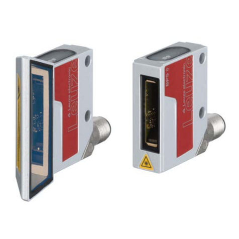
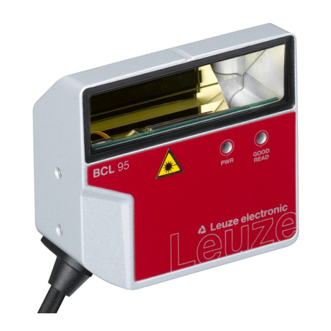
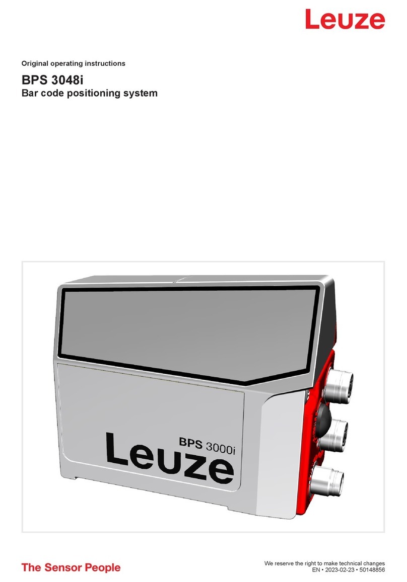
Leuze BCL 8 User manual

BCL 8
Bar code reader with integrated decoder
Original operating instructions
EN 2022-04-14 50127073
We reserve the right to make technical changes

Leuze electronic GmbH + Co. KG BCL 8 2
© 2022
Leuze electronic GmbH + Co. KG
In der Braike 1
D-73277 Owen / Germany
Phone: +49 7021 573-0
Fax: +49 7021 573-199
http://www.leuze.com

Leuze electronic GmbH + Co. KG BCL 8 3
1 General information . . . . . . . . . . . . . . . . . . . . . . . . . . . . . . . . . . . . . . . . . . . . . . . . . . . . 6
1.1 Explanation of symbols . . . . . . . . . . . . . . . . . . . . . . . . . . . . . . . . . . . . . . . . . . . . . . . . . . . . . . . . . . . 6
1.2 Declaration of Conformity . . . . . . . . . . . . . . . . . . . . . . . . . . . . . . . . . . . . . . . . . . . . . . . . . . . . . . . . . 6
2 Safety . . . . . . . . . . . . . . . . . . . . . . . . . . . . . . . . . . . . . . . . . . . . . . . . . . . . . . . . . . . . . . . 7
2.1 Intended use . . . . . . . . . . . . . . . . . . . . . . . . . . . . . . . . . . . . . . . . . . . . . . . . . . . . . . . . . . . . . . . . . . . 7
2.2 Foreseeable misuse . . . . . . . . . . . . . . . . . . . . . . . . . . . . . . . . . . . . . . . . . . . . . . . . . . . . . . . . . . . . . 8
2.3 Competent persons . . . . . . . . . . . . . . . . . . . . . . . . . . . . . . . . . . . . . . . . . . . . . . . . . . . . . . . . . . . . . . 8
2.4 Exemption of liability . . . . . . . . . . . . . . . . . . . . . . . . . . . . . . . . . . . . . . . . . . . . . . . . . . . . . . . . . . . . . 8
2.5 Laser safety notices. . . . . . . . . . . . . . . . . . . . . . . . . . . . . . . . . . . . . . . . . . . . . . . . . . . . . . . . . . . . . . 8
3 Description . . . . . . . . . . . . . . . . . . . . . . . . . . . . . . . . . . . . . . . . . . . . . . . . . . . . . . . . . . 10
3.1 The BCL 8 bar code reader . . . . . . . . . . . . . . . . . . . . . . . . . . . . . . . . . . . . . . . . . . . . . . . . . . . . . . . 10
3.2 Stand-alone operation . . . . . . . . . . . . . . . . . . . . . . . . . . . . . . . . . . . . . . . . . . . . . . . . . . . . . . . . . . . 10
3.3 Daisy chain network. . . . . . . . . . . . . . . . . . . . . . . . . . . . . . . . . . . . . . . . . . . . . . . . . . . . . . . . . . . . . 10
4 Technical data . . . . . . . . . . . . . . . . . . . . . . . . . . . . . . . . . . . . . . . . . . . . . . . . . . . . . . . 12
4.1 General specifications BCL 8 . . . . . . . . . . . . . . . . . . . . . . . . . . . . . . . . . . . . . . . . . . . . . . . . . . . . . 12
4.2 LED indicators . . . . . . . . . . . . . . . . . . . . . . . . . . . . . . . . . . . . . . . . . . . . . . . . . . . . . . . . . . . . . . . . . 13
4.3 Dimensioned and connection drawings . . . . . . . . . . . . . . . . . . . . . . . . . . . . . . . . . . . . . . . . . . . . . . 14
4.4 Optical data . . . . . . . . . . . . . . . . . . . . . . . . . . . . . . . . . . . . . . . . . . . . . . . . . . . . . . . . . . . . . . . . . . . 16
4.4.1 Type overview . . . . . . . . . . . . . . . . . . . . . . . . . . . . . . . . . . . . . . . . . . . . . . . . . . . . . . . . . . . . . . . 16
4.4.2 Reading fields . . . . . . . . . . . . . . . . . . . . . . . . . . . . . . . . . . . . . . . . . . . . . . . . . . . . . . . . . . . . . . . 16
5 Accessories/order codes . . . . . . . . . . . . . . . . . . . . . . . . . . . . . . . . . . . . . . . . . . . . . . . 18
5.1 Accessories overview . . . . . . . . . . . . . . . . . . . . . . . . . . . . . . . . . . . . . . . . . . . . . . . . . . . . . . . . . . . 18
5.2 MA 8.1 connection unit . . . . . . . . . . . . . . . . . . . . . . . . . . . . . . . . . . . . . . . . . . . . . . . . . . . . . . . . . . 19
5.2.1 Electrical connection MA 8.1 . . . . . . . . . . . . . . . . . . . . . . . . . . . . . . . . . . . . . . . . . . . . . . . . . . . . 20
5.2.2 MA 8.1 - PWR IN HOST/RS232 - voltage supply and RS 232 . . . . . . . . . . . . . . . . . . . . . . . . . . 20
5.2.3 MA 8.1 - SW IN/OUT – switching input and switching output . . . . . . . . . . . . . . . . . . . . . . . . . . . 21
5.2.4 MA 8.1 - BCL - connecting the BCL 8 to the MA 8.1 . . . . . . . . . . . . . . . . . . . . . . . . . . . . . . . . . . 22
5.3 Connection unit MA 8-01 . . . . . . . . . . . . . . . . . . . . . . . . . . . . . . . . . . . . . . . . . . . . . . . . . . . . . . . . . 23
5.3.1 MA 8-01 - PWR IN HOST/RS485 - Voltage supply and RS 485 . . . . . . . . . . . . . . . . . . . . . . . . . 24
5.3.2 MA 8-01 - SW IN/OUT - switching input and switching output . . . . . . . . . . . . . . . . . . . . . . . . . . 24
5.3.3 MA 8-01 - BCL - connecting the BCL 8 to the MA 8-01. . . . . . . . . . . . . . . . . . . . . . . . . . . . . . . . 25
5.3.4 Termination of the RS 485 interface . . . . . . . . . . . . . . . . . . . . . . . . . . . . . . . . . . . . . . . . . . . . . . 26
5.4 Mounting accessories . . . . . . . . . . . . . . . . . . . . . . . . . . . . . . . . . . . . . . . . . . . . . . . . . . . . . . . . . . . 26
6 Installation . . . . . . . . . . . . . . . . . . . . . . . . . . . . . . . . . . . . . . . . . . . . . . . . . . . . . . . . . . 27
6.1 Storage, transportation . . . . . . . . . . . . . . . . . . . . . . . . . . . . . . . . . . . . . . . . . . . . . . . . . . . . . . . . . . 27
6.2 Mounting . . . . . . . . . . . . . . . . . . . . . . . . . . . . . . . . . . . . . . . . . . . . . . . . . . . . . . . . . . . . . . . . . . . . . 27
6.2.1 Device arrangement . . . . . . . . . . . . . . . . . . . . . . . . . . . . . . . . . . . . . . . . . . . . . . . . . . . . . . . . . . 28
6.3 Connecting. . . . . . . . . . . . . . . . . . . . . . . . . . . . . . . . . . . . . . . . . . . . . . . . . . . . . . . . . . . . . . . . . . . . 29
6.3.1 Connecting the BCL 8 . . . . . . . . . . . . . . . . . . . . . . . . . . . . . . . . . . . . . . . . . . . . . . . . . . . . . . . . . 29
6.3.2 Connecting the switching input/output . . . . . . . . . . . . . . . . . . . . . . . . . . . . . . . . . . . . . . . . . . . . . 29
6.3.3 Cable lengths. . . . . . . . . . . . . . . . . . . . . . . . . . . . . . . . . . . . . . . . . . . . . . . . . . . . . . . . . . . . . . . . 31
6.4 Disassembling, packing, disposing . . . . . . . . . . . . . . . . . . . . . . . . . . . . . . . . . . . . . . . . . . . . . . . . . 31
7 Commissioning. . . . . . . . . . . . . . . . . . . . . . . . . . . . . . . . . . . . . . . . . . . . . . . . . . . . . . . 32
7.1 Measures to be performed prior to the initial commissioning . . . . . . . . . . . . . . . . . . . . . . . . . . . . . 32
7.2 Function Test . . . . . . . . . . . . . . . . . . . . . . . . . . . . . . . . . . . . . . . . . . . . . . . . . . . . . . . . . . . . . . . . . . 32
7.3 Setting the parameters . . . . . . . . . . . . . . . . . . . . . . . . . . . . . . . . . . . . . . . . . . . . . . . . . . . . . . . . . . 32
7.3.1 Parameter sets . . . . . . . . . . . . . . . . . . . . . . . . . . . . . . . . . . . . . . . . . . . . . . . . . . . . . . . . . . . . . . 32

Leuze electronic GmbH + Co. KG BCL 8 4
7.3.2 Service operating mode. . . . . . . . . . . . . . . . . . . . . . . . . . . . . . . . . . . . . . . . . . . . . . . . . . . . . . . . 33
8 Operation . . . . . . . . . . . . . . . . . . . . . . . . . . . . . . . . . . . . . . . . . . . . . . . . . . . . . . . . . . . 34
8.1 Display elements . . . . . . . . . . . . . . . . . . . . . . . . . . . . . . . . . . . . . . . . . . . . . . . . . . . . . . . . . . . . . . . 34
8.2 Error handling . . . . . . . . . . . . . . . . . . . . . . . . . . . . . . . . . . . . . . . . . . . . . . . . . . . . . . . . . . . . . . . . . 34
9 Configuration and diagnostics software - Sensor Studio . . . . . . . . . . . . . . . . . . . . . . . 35
9.1 System requirements. . . . . . . . . . . . . . . . . . . . . . . . . . . . . . . . . . . . . . . . . . . . . . . . . . . . . . . . . . . . 35
9.2 Installing Sensor Studio . . . . . . . . . . . . . . . . . . . . . . . . . . . . . . . . . . . . . . . . . . . . . . . . . . . . . . . . . . 36
9.2.1 Downloading configuration software . . . . . . . . . . . . . . . . . . . . . . . . . . . . . . . . . . . . . . . . . . . . . . 36
9.2.2 Installing the Sensor Studio FDT frame. . . . . . . . . . . . . . . . . . . . . . . . . . . . . . . . . . . . . . . . . . . . 36
9.2.3 Installing communication DTM and device DTM . . . . . . . . . . . . . . . . . . . . . . . . . . . . . . . . . . . . . 36
9.2.4 Connecting device to PC . . . . . . . . . . . . . . . . . . . . . . . . . . . . . . . . . . . . . . . . . . . . . . . . . . . . . . . 36
9.3 Starting Sensor Studio. . . . . . . . . . . . . . . . . . . . . . . . . . . . . . . . . . . . . . . . . . . . . . . . . . . . . . . . . . . 36
9.4 Exiting Sensor Studio . . . . . . . . . . . . . . . . . . . . . . . . . . . . . . . . . . . . . . . . . . . . . . . . . . . . . . . . . . . 38
9.5 Configuration parameters . . . . . . . . . . . . . . . . . . . . . . . . . . . . . . . . . . . . . . . . . . . . . . . . . . . . . . . . 38
9.5.1 Decode tab . . . . . . . . . . . . . . . . . . . . . . . . . . . . . . . . . . . . . . . . . . . . . . . . . . . . . . . . . . . . . . . . . 38
9.5.2 Output tab . . . . . . . . . . . . . . . . . . . . . . . . . . . . . . . . . . . . . . . . . . . . . . . . . . . . . . . . . . . . . . . . . . 41
9.5.3 Control tab . . . . . . . . . . . . . . . . . . . . . . . . . . . . . . . . . . . . . . . . . . . . . . . . . . . . . . . . . . . . . . . . . . 43
9.5.4 Host interface tab. . . . . . . . . . . . . . . . . . . . . . . . . . . . . . . . . . . . . . . . . . . . . . . . . . . . . . . . . . . . . 44
9.5.5 Reference code tab . . . . . . . . . . . . . . . . . . . . . . . . . . . . . . . . . . . . . . . . . . . . . . . . . . . . . . . . . . . 45
9.5.6 Switching input tab. . . . . . . . . . . . . . . . . . . . . . . . . . . . . . . . . . . . . . . . . . . . . . . . . . . . . . . . . . . . 46
9.5.7 Switch tab . . . . . . . . . . . . . . . . . . . . . . . . . . . . . . . . . . . . . . . . . . . . . . . . . . . . . . . . . . . . . . . . . . 47
9.6 Diagnosis . . . . . . . . . . . . . . . . . . . . . . . . . . . . . . . . . . . . . . . . . . . . . . . . . . . . . . . . . . . . . . . . . . . . . 48
9.7 Firmware Reload . . . . . . . . . . . . . . . . . . . . . . . . . . . . . . . . . . . . . . . . . . . . . . . . . . . . . . . . . . . . . . . 48
10 Starting up the device – Configuration . . . . . . . . . . . . . . . . . . . . . . . . . . . . . . . . . . . . . 50
10.1 Measures to be performed prior to the initial commissioning . . . . . . . . . . . . . . . . . . . . . . . . . . . . . 50
10.2 Starting the device . . . . . . . . . . . . . . . . . . . . . . . . . . . . . . . . . . . . . . . . . . . . . . . . . . . . . . . . . . . . . . 50
10.2.1 Power-on test. . . . . . . . . . . . . . . . . . . . . . . . . . . . . . . . . . . . . . . . . . . . . . . . . . . . . . . . . . . . . . . . 50
10.2.2 Interface. . . . . . . . . . . . . . . . . . . . . . . . . . . . . . . . . . . . . . . . . . . . . . . . . . . . . . . . . . . . . . . . . . . . 50
10.2.3 Online commands . . . . . . . . . . . . . . . . . . . . . . . . . . . . . . . . . . . . . . . . . . . . . . . . . . . . . . . . . . . . 50
10.2.4 Problems . . . . . . . . . . . . . . . . . . . . . . . . . . . . . . . . . . . . . . . . . . . . . . . . . . . . . . . . . . . . . . . . . . . 50
10.3 Starting up with factory settings. . . . . . . . . . . . . . . . . . . . . . . . . . . . . . . . . . . . . . . . . . . . . . . . . . . . 50
10.4 Setting the configuration parameters. . . . . . . . . . . . . . . . . . . . . . . . . . . . . . . . . . . . . . . . . . . . . . . . 51
10.4.1 Service mode. . . . . . . . . . . . . . . . . . . . . . . . . . . . . . . . . . . . . . . . . . . . . . . . . . . . . . . . . . . . . . . . 51
10.4.2 Parameter sets . . . . . . . . . . . . . . . . . . . . . . . . . . . . . . . . . . . . . . . . . . . . . . . . . . . . . . . . . . . . . . 52
11 Online commands . . . . . . . . . . . . . . . . . . . . . . . . . . . . . . . . . . . . . . . . . . . . . . . . . . . . 53
11.1 Overview of commands and parameters . . . . . . . . . . . . . . . . . . . . . . . . . . . . . . . . . . . . . . . . . . . . . 53
11.1.1 General online commands. . . . . . . . . . . . . . . . . . . . . . . . . . . . . . . . . . . . . . . . . . . . . . . . . . . . . . 53
11.1.2 Online commands for system control . . . . . . . . . . . . . . . . . . . . . . . . . . . . . . . . . . . . . . . . . . . . . 57
11.1.3 ’Online’ commands for parameter set operations . . . . . . . . . . . . . . . . . . . . . . . . . . . . . . . . . . . . 58
12 Maintenance. . . . . . . . . . . . . . . . . . . . . . . . . . . . . . . . . . . . . . . . . . . . . . . . . . . . . . . . . 61
12.1 General maintenance information . . . . . . . . . . . . . . . . . . . . . . . . . . . . . . . . . . . . . . . . . . . . . . . . . . 61
12.2 Repairs, servicing . . . . . . . . . . . . . . . . . . . . . . . . . . . . . . . . . . . . . . . . . . . . . . . . . . . . . . . . . . . . . . 61
12.3 Diagnostics and troubleshooting . . . . . . . . . . . . . . . . . . . . . . . . . . . . . . . . . . . . . . . . . . . . . . . . . . . 61
12.4 Service and support. . . . . . . . . . . . . . . . . . . . . . . . . . . . . . . . . . . . . . . . . . . . . . . . . . . . . . . . . . . . . 62
12.5 Example bar code label types . . . . . . . . . . . . . . . . . . . . . . . . . . . . . . . . . . . . . . . . . . . . . . . . . . . . . 63

Leuze electronic GmbH + Co. KG BCL 8 5
Figure 2.1: Laser apertures, laser warning signs............................................................................................ 9
Figure 3.1: Device construction of the BCL 8 ............................................................................................... 10
Table 4.1: Technical data ............................................................................................................................ 12
Table 4.2: LED indicators ............................................................................................................................ 13
Figure 4.1: Dimensioned drawing BCL 8 S M …0, BCL 8 S N …0 with lateral beam exit............................ 14
Figure 4.2: Dimensioned drawing BCL8SM…2, BCL8SN…2 with front beam exit .............................. 15
Table 4.3: Type overview - M optics ............................................................................................................ 16
Table 4.4: Type overview - N optics ............................................................................................................ 16
Figure 4.3: Reading field of BCL 8 S M … with M optics (medium density) ................................................. 17
Figure 4.4: Reading field of BCL 8 S N … with N optics (high density) ........................................................ 17
Table 5.1: Accessories/order codes ............................................................................................................ 18
Figure 5.1: Photo and dimensioned drawing of the MA 8.1 connection unit................................................. 19
Figure 5.2: Electrical connection MA 8.1 ...................................................................................................... 20
Figure 5.3: MA 8.1 - Pin assignment PWR IN HOST/RS232........................................................................ 20
Figure 5.4: MA 8.1 - Pin assignment SW IN/OUT......................................................................................... 21
Figure 5.5: Connection of the switching input/output of the MA 8.1.............................................................. 21
Figure 5.6: MA 8.1 - Pin assignment BCL..................................................................................................... 22
Figure 5.7: Pin assignment - MA 8-01 .......................................................................................................... 23
Figure 5.8: MA 8-01 - Pin assignment PWR IN HOST/RS485 ..................................................................... 24
Figure 5.9: MA 8-01 - Pin assignment SW IN/OUT ...................................................................................... 24
Figure 5.10: Electrical connection MA 8-01 .................................................................................................... 25
Figure 5.11: MA 8-01 - Pin assignment BCL .................................................................................................. 25
Figure 5.12: Termination of the RS 485 interface in the MA 8-01................................................................... 26
Figure 5.13: Universal rod mounting system for BCL 8 .................................................................................. 26
Figure 6.1: BCL 8 device name plate............................................................................................................ 27
Figure 6.2: Definition of the BCL 8 reading angles ....................................................................................... 28
Figure 6.3: BCL 8 pin assignment................................................................................................................. 29
Table 6.1: Wiring description BCL 8 ............................................................................................................ 29
Figure 6.4: Switching input for BCL 8 connection version 1 (standard setting) ............................................ 30
Figure 6.5: Switching input for BCL 8 connection version 2 (setting "inverted") ........................................... 30
Figure 6.6: Switching output BCL 8 .............................................................................................................. 30
Table 6.2: Cable lengths.............................................................................................................................. 31
Figure 7.1: Bar code label "Service" ............................................................................................................. 33
Figure 7.2: Connecting the RS 232 interface to a PC or terminal................................................................. 33
Table 9.1: System requirements for
Sensor Studio
installation ................................................................... 35
Figure 9.1: Device selection for the BCL 8 ................................................................................................... 37
Figure 9.2: Configuration project: Device manager for BCL 8 ......................................................................37
Figure 9.3: Decode tab ................................................................................................................................. 38
Figure 9.4: Standard settings of the Properties dialog box (SYMBOLOGY PROPERTIES) ........................ 39
Figure 9.5: Standard settings of the Properties dialog box (COMMON PROPERTIES)............................... 40
Figure 9.6:
Output
tab (OUTPUT FORMAT)................................................................................................. 41
Figure 9.7: Properties dialog box (COMMON PROPERTIES)...................................................................... 42
Figure 9.8:
Control
tab .................................................................................................................................. 43
Figure 9.9:
Host Interface
tab ....................................................................................................................... 44
Figure 9.10: Standard settings of the Properties dialog box (FRAMING PROTOCOL)..................................44
Figure 9.11:
Reference Code
tab.................................................................................................................... 45
Figure 9.12: Standard settings of the Properties dialog box (PROPERTIES) ................................................ 46
Figure 9.13:
Switching input
tab...................................................................................................................... 46
Figure 9.14:
Switching output
tab ................................................................................................................... 47
Figure 9.15:
Diagnosis
tab .............................................................................................................................. 48
Figure 9.16: Firmware Reload ........................................................................................................................ 49
Figure 10.1: Bar code label "Service" ............................................................................................................. 52
Figure 12.1: Example bar code label types..................................................................................................... 63
General information
Leuze electronic GmbH + Co. KG BCL 8 6
1 General information
1.1 Explanation of symbols
The symbols used in this technical description are explained below.
1.2 Declaration of Conformity
The BCL 8 bar code reader and the optional MA 8.1 connection unit have been developed and produced
in accordance with the applicable European standards and directives.
The manufacturer of the product, Leuze electronic GmbH & Co. KG in D-73277 Owen, possesses a certi-
fied quality assurance system in accordance with ISO 9001.
ATTENTION!
This symbol precedes text messages which must strictly be observed. Failure to observe the
provided instructions could lead to personal injury or damage to equipment.
NOTE
This symbol indicates text passages containing important information.
NOTE
The corresponding declaration of conformity can be requested from the manufacturer.

Safety
Leuze electronic GmbH + Co. KG BCL 8 7
2 Safety
This sensor was developed, manufactured and tested in line with the applicable safety standards. It corre-
sponds to the state of the art.
2.1 Intended use
The BCL 8 bar code reader is designed as a stationary scanner with integrated decoder for all common
bar codes used for automatic object detection.
The optional MA 8.1 connection unit is intended for the easy connection of a bar code reader of type
BCL 8.
Areas of application
The BCL 8 bar code reader with optional MA 8.1 connection unit is designed especially for the following
fields of application:
• Labeling and packaging machines
• Automatic analyzers
• For space-critical bar code reading tasks
• Material flow
• Pharmaceutical industry
• Robotics and automation technology
CAUTION!
Observe intended use!
Only operate the device in accordance with its intended use.
The protection of personnel and the device cannot be guaranteed if the device is operated in
a manner not complying with its intended use.
Leuze electronic GmbH + Co. KG is not liable for damages caused by improper use.
Read the technical description before commissioning the device.
Knowledge of this technical description is an element of proper use.
NOTE
Comply with conditions and regulations!
Observe the locally applicable legal regulations and the rules of the employer's liability insur-
ance association.
ATTENTION!
For UL applications, use is only permitted in Class 2 circuits in accordance with the NEC
(National Electric Code).

Safety
Leuze electronic GmbH + Co. KG BCL 8 8
2.2 Foreseeable misuse
Any use other than that defined under "Intended use" or which goes beyond that use is considered
improper use.
In particular, use of the device is not permitted in the following cases:
• in rooms with explosive atmospheres
• as stand-alone safety component in accordance with the machinery directive 1)
• for medical purposes
2.3 Competent persons
Connection, mounting, commissioning and adjustment of the device must only be carried out by competent
persons.
Prerequisites for competent persons:
• They have a suitable technical education.
• They are familiar with the rules and regulations for occupational safety and safety at work.
• They are familiar with the technical description of the device.
• They have been instructed by the responsible person on the mounting and operation of the device.
Certified electricians
Electrical work must be carried out by a certified electrician.
Due to their technical training, knowledge and experience as well as their familiarity with relevant stan-
dards and regulations, certified electricians are able to perform work on electrical systems and indepen-
dently detect possible dangers.
In Germany, certified electricians must fulfill the requirements of accident-prevention regulations DGUV
V3 (e.g. electrician foreman). In other countries, there are respective regulations that must be observed.
2.4 Exemption of liability
Leuze electronic GmbH + Co. KG is not liable in the following cases:
• The device is not being used properly.
• Reasonably foreseeable misuse is not taken into account.
• Mounting and electrical connection are not properly performed.
• Changes (e.g., constructional) are made to the device.
2.5 Laser safety notices
1) Use as safety-related component within the safety function is possible, if the component combination is designed corre-
spondingly by the machine manufacturer.
NOTE
Do not modify or otherwise interfere with the device!
Do not carry out modifications or otherwise interfere with the device.
The device must not be tampered with and must not be changed in any way.
The device must not be opened. There are no user-serviceable parts inside.
Repairs must only be performed by Leuze electronic GmbH + Co. KG.
ATTENTION, LASER RADIATION – CLASS 1 LASER PRODUCT
The device satisfies the requirements of IEC/EN 60825-1:2014 safety regulations for a product
of laser class 1 and complies with 21 CFR 1040.10 except for conformance with IEC 60825-1
Ed. 3., as described in Laser Notice No. 56, dated May 8, 2019.
Observe the applicable statutory and local laser protection regulations.
The device must not be tampered with and must not be changed in any way.
There are no user-serviceable parts inside.
Repairs must only be performed by Leuze electronic GmbH + Co. KG.

Safety
Leuze electronic GmbH + Co. KG BCL 8 9
Figure 2.1: Laser apertures, laser warning signs
ALaser aperture
BLaser warning sign
A
B
A
B
BCL 8 S …2
BCL 8 S …0

Description
Leuze electronic GmbH + Co. KG BCL 8 10
3 Description
Device construction of the BCL 8
Figure 3.1: Device construction of the BCL 8
3.1 The BCL 8 bar code reader
The BCL 8 bar code reader is a laser scanner with integrated decoder for all commonly used bar codes,
e.g. 2/5 Interleaved, Code 39, Code 128, EAN etc., with an extremely small housing.
The many possible configurations of the device allow it to be adapted to a multitude of reading tasks. Due
to the small dimensions of the unit and its large reading field, the BCL 8 may also be used in highly
constrained spaces.
For information on technical data and characteristics, refer to Chapter 4.
3.2 Stand-alone operation
The BCL 8 bar code reader is operated as a "stand-alone" device. It is equipped with a 5-wire cable with
open ends or a 5-pin M12 connector for the electrical connection of the supply voltage, the interface and
the switching input.
With MA 8.1 connection unit
The MA 8.1 connection unit simplifies the electrical installation of the bar code reader in stand-alone oper-
ation with an RS 232 interface.
For details on the connection units, see Chapter 5.
With MA 8-01 connection unit
The MA 8-01 connection unit simplifies the electrical installation of the bar code reader in stand-alone
operation with an RS 485 interface.
For details on the connection units, see Chapter 5.
3.3 Daisy chain network
A daisy chain is a network based on the RS 232 interface. All devices, which consist of a transmitter and
a receiver, are connected to one another to form a ring. The transmitter of one device is directly connected
to the receiver of the next device until all devices are connected together to form a ring. One device
performs the task of the host system.
Reading window with
lateral beam exit
Two M4 mounting threads at the rear and bottom side of the device
M12 connector, turning or
cable, 2m
BCL8SMxx2
BCL8SNxx2
BCL8SMxx0
BCL8SNxx0
M12 connector, turning or
cable, 2m
Reading window with
front beam exit
Through holes
4.4 for fastening
Through holes
4.4 for fastening

Description
Leuze electronic GmbH + Co. KG BCL 8 11
Ideally, all BCL 8 devices are to be connected to one another with MA 8.1 connection units so that:
• the voltage supply of the BCL 8/MA 8.1 is ensured.
• TxD to RxD of the RS 232 is established from one BCL 8 to the next (host).
• the switching outputs and inputs are connected (optional).
A maximum of seven BCL 8 devices may be operated in the daisy chain together with one host. Further
information is available from your Leuze sales office.

Technical data
Leuze electronic GmbH + Co. KG BCL 8 12
4 Technical data
4.1 General specifications BCL 8
Optical data
Light source Laser diode
Laser class 1 acc. to IEC/EN 60825-1:2014 and U.S. 21 CFR 1040.10 with
Laser Notice No. 56
Wavelength 655nm
Scanning rate M optics: 600 scans/s
N optics: 500 scans/s
Resolution M optics: m = 0.150 … 0.500 mm / 6 … 20 mil
N optics: m = 0.127 … 0.400 mm / 5 … 16 mil
Beam deflection Via rotating polygon wheel
Beam exit Front, alternatively on the side with deflection mirror (105°)
Reading distance See reading fields
Reading field opening See reading fields
Code types 2/5 Interleaved, Code 39, Code 128, EAN 128, EAN/UPC, EAN
Addendum, Codabar, Pharma Code, Code 93
Software features Selectable output format, autoConfig, autoReflAct, reference
code comparison, multiple read, real time decoding, adjustment
mode, control of switching input or switching output, etc.
Electrical data
Interface type RS 232, freely configurable
Baud rate 4800 … 57600 Bd
Data formats Data bits: 7, 8
Parity: none, even, odd
Stop bit: 1, 2
Protocols Framing protocol with/without acknowledgment
Software handshake X ON / X OFF
Service interface RS 232 with fixed data format,
9600Bd, 8 data bits, no parity, 1 stop bit
<STX> <data> <CR><LF>
Ports 1 switching input 5VDC
or
1 switching output 5 … 30V, 20mA
LEDs 1 device status
1 read status
Operating voltage 4.75 … 5.5VDC, protection class III - PELV 1)
(Protective Extra Low Voltage)
Current consumption Max. 250 mA (2 W power supply unit recommended)
Mechanical data
Degree of protection IP 67
Connection type M12 connector, 5-pin, turnable or
Fixed cable, 2 m long, 5 x 0.25 mm2
Weight 70g
Dimensions (H x W x D) Front beam exit: 48 x 40.3 x 15 mm
Lateral beam exit: 48 x 58 x 17.4 mm
Housing Metal (diecast zinc)
Environmental data
Ambient temp.
(operation/storage) 0°C … +40°C/-20°C … +60°C
Air humidity Max. 90% rel. humidity, non-condensing
Vibration IEC 60068-2-6, test Fc
Shock IEC 60068-2-27, test Ea
Table 4.1: Technical data

Technical data
Leuze electronic GmbH + Co. KG BCL 8 13
4.2 LED indicators
Two, 3-color LEDs on the top of the housing indicate the device and read status:
Table 4.2: LED indicators
Electromagnetic compatibility EN 55022, IEC 61000-4-2, -3, -4 and -6,
Conformity CE, FCC Class B, CDRH
Certifications UL 60950-1, C22.2 No. 60950-1 1) 2)
1) For UL applications: use is permitted exclusively in Class 2 circuits according to NEC
2) These bar code readers shall be used with UL Listed Cable assemblies rated 30V,
0.5A min, in the field installation, or equivalent (categories: CYJV/CYJV7 or PVVA/PVVA7)
Table 4.1: Technical data
LED Color Meaning
Status
LED
Green, flashing Initialization phase
Green, continuous Operational readiness
Red, flashing (200 ms) Warning
Red, continuous Error, no function
Orange, flashing
(200 ms)
Service operation
Decode
LED
Green (200ms on) Reading successful
Red (200ms off) No read result
Orange, continuous Reading gate active

Technical data
Leuze electronic GmbH + Co. KG BCL 8 14
4.3 Dimensioned and connection drawings
BCL 8 S M …0, BCL 8 S N …0 with lateral beam exit
Figure 4.1: Dimensioned drawing BCL 8 S M …0, BCL 8 S N …0 with lateral beam exit
ATurning connector, turnable 90°
BIndicator LEDs (B1: status LED, B2: decode LED)
CScanning beam, divergence max. 5mm at 150 mm reading distance
DOptical axis
Thread depth:
3mm
Thread depth:
3mm

Technical data
Leuze electronic GmbH + Co. KG BCL 8 15
BCL 8 S M …2, BCL 8 S N …2 with front beam exit
Figure 4.2: Dimensioned drawing BCL 8 S M …2, BCL 8 S N …2 with front beam exit
ATurning connector, turnable 90°
BIndicator diodes (B1: status LED, B2: decode LED)
CScanning beam, divergence max. 5mm at 150 mm reading distance
DOptical axis
Thread depth:
3mm
Thread depth:
3mm

Technical data
Leuze electronic GmbH + Co. KG BCL 8 16
4.4 Optical data
For different reading task and connection requirements, the BCL 8 is available in various models (see
chapter 4.4.1 "Type overview").
4.4.1 Type overview
BCL 8 with M optics
Table 4.3: Type overview - M optics
BCL 8 with N optics
Table 4.4: Type overview - N optics
4.4.2 Reading fields
NOTE
Please note that the size of the bar code module influences the maximum reading distance and
the width of the reading field. Therefore, when selecting a mounting location and/or the bar code
label, take into account the different reading characteristics of the scanner with various bar code
modules.
Type Operating
range
Module/
resolution
[mm]
Connection Scanner type/
Beam exit
Part no.
BCL8SM100
Up to 160mm 0.15 … 0.5
M12
connector
Single line/
Lateral 50040229
BCL8SM102 Single line/
Front 50038949
BCL8SM550
Fixed cable
(2m)
Single line/
Lateral 50040230
BCL8SM552 Single line/
Front 50038948
Type Operating
range
Module/
resolution
[mm]
Connection Scanner type/
Beam exit
Part no.
BCL8SN100
Up to 120mm 0.125 … 0.4
M12
connector
Single line/
Lateral 50105417
BCL8SN102 Single line/
Front 50105418
BCL8SN550
Fixed cable
(2m)
Single line/
Lateral 50105419
BCL8SN552 Single line/
Front 50105420
NOTE
Please note that the actual reading fields are also influenced by factors such as labeling material,
printing quality, reading angle, printing contrast etc., and may thus deviate from the reading fields
specified here. The origin of the read distance always refers to the front edge of the housing of
the beam exit.

Technical data
Leuze electronic GmbH + Co. KG BCL 8 17
Reading field of BCL 8 with M optics
Figure 4.3: Reading field of BCL 8 S M … with M optics (medium density)
Reading field of BCL 8 with N optics
Figure 4.4: Reading field of BCL 8 S N … with N optics (high density)
-70
-60
-50
-40
-30
-20
-10
0
10
20
30
40
50
60
70
0 10 20 30 40 50 60 70 80 90 100 110 120 130 140 150 160 170
0 10 20 30 40 50 60 70 80 90 100 110 120 130 140 150
m=0.150 mm
(6 mil)
m=0.2 mm
(8 mil)
m=0.3 mm
(12 mil)
m=0.5 mm
(20 mil)
BCL 8 S M 100
BCL 8 S M 550
BCL 8 S M 102
BCL 8 S M 552
Reading field width in mm
Distance in mm
Code 2/5 int.
Ratio 1:2.5
Class A acc. to ANSI
Front beam
exit
Lateral beam
exit
m=0.127 mm
(5 mil)
m=0.15 mm
(6 mil)
m=0.2 mm
(8 mil)
m=0.25 mm
(10 mil)
-70
-60
-50
-40
-30
-20
-10
0
10
20
30
40
50
60
70
0 10 20 30 40 50 60 70 80 90 100 110 120 130 140 150 160 170
0 102030405060708090100110
BCL 8 SN 100
BCL 8 SN 550
BCL 8 SN 102
BCL 8 SN 552
Reading field width in mm
Distance in mm
Code 2/5 int.
Ratio 1:2.5
Class A acc. to ANSI
Front beam
exit
Lateral beam
exit

Accessories/order codes
Leuze electronic GmbH + Co. KG BCL 8 18
5 Accessories/order codes
5.1 Accessories overview
Table 5.1: Accessories/order codes
Designation Part no. Short description
MA 8.1 50101699 MA 8.1 connection unit for BCL 8,
RS 232 point-to-point connection,
1 switching input and 1 switching output, 24V DC
MA 8-01 50104790 MA 8-01 connection unit for BCL 8,
RS 485 point-to-point connection,
1 switching input and 1 switching output, 24V DC
BT 8-0 50036196 Mounting device with dovetail
BT 300M.5 50118543 Mounting bracket, stainless steel
BTU 300M-D10 50117253 Sensor mounting bracket for rod 10 mm
or cheek 1.5 … 4 mm
BTU 300M-D12 50117252 Sensor mounting bracket for rod 12 mm
or cheek 1.5 … 4 mm
BTU 300M-D14 50117251 Sensor mounting bracket for rod 14 mm
or cheek 1.5 … 4 mm
BTU D12M.5-150 50119323 Rod 12 mm, length 150 mm, stainless steel
BTU D12M.5-250 50119324 Rod 12 mm, length 250 mm, stainless steel
BTU D12M-D12-A090 50119323 90°-connector for 2 rods 12 mm
BTU D12M-D12-B090 50119333 Mounting bracket for rods 12 mm,
system-side mounting bracket 2 x M6,
hole spacing 27 mm … 45 mm, diecast aluminum
BTP 300M-D10 50117827 Sensor protective cover for rod 10 mm
or cheek 1.5 … 4 mm
BTP 300M-D12 50117826 Sensor protective cover for rod 12 mm
or cheek 1.5 … 4 mm
BTP 300M-D14 50117825 Sensor protective cover for rod 14 mm
or cheek 1.5 … 4 mm
Reflective tape no. 4
100 x 100 mm
50106119 Reflective tape as reflector for AutoReflAct operation
Sensor Studio Download at
www.leuze.com
Configuration software

Accessories/order codes
Leuze electronic GmbH + Co. KG BCL 8 19
5.2 MA 8.1 connection unit
The MA 8.1 connection unit is used to simplify the electrical installation of the BCL 8. The connection unit
offers the following advantages over the installation of the BCL 8 as a stand-alone device:
• M12 socket for switching input and switching output
• M12 connector for RS 232 interface and voltage supply 24VDC
• M12 socket for connection of the BCL 8
Figure 5.1: Photo and dimensioned drawing of the MA 8.1 connection unit
AM12 socket, 5-pin
BM12 connector, 5-pin

Accessories/order codes
Leuze electronic GmbH + Co. KG BCL 8 20
5.2.1 Electrical connection MA 8.1
Figure 5.2: Electrical connection MA 8.1
5.2.2 MA 8.1 - PWR IN HOST/RS232 - voltage supply and RS 232
Figure 5.3: MA 8.1 - Pin assignment PWR IN HOST/RS232
M12 socket
(A-coded)
M12 socket
(A-coded)
M12 connector
(A-coded)
S
S
PWR IN HOST/RS232 (5-pin connector, A-coded)
Pin Name Comment
1VINPositive supply voltage: +10 … +30VDC
2TXDRS 232 transmit data from the BCL 8 to the host
3GNDSupply voltage: 0VDC
4RXDRS 232 receive data from the host to the BCL 8
5FEFunctional earth
Thread FE Functional earth (housing)
ATTENTION!
Degree of protection IP 67 is achieved only if the connectors and caps are screwed into place!
3
21
4
5
RXD GND
VIN
FE
TXD
PWR IN
HOST/RS232
M12 connector
(A-coded)
Table of contents
Other Leuze Barcode Reader manuals

Leuze
Leuze BCL 92 User manual

Leuze
Leuze HS 6508 User manual

Leuze
Leuze IT 3800g User manual

Leuze
Leuze IT 6320 DPM Setup guide

Leuze
Leuze DCR 258i User manual

Leuze
Leuze BCL34 Parts list manual

Leuze
Leuze BCL 308i User manual

Leuze
Leuze BPS 348i User manual

Leuze
Leuze BCL 900i User manual

Leuze
Leuze it 3820 User manual

Leuze
Leuze BCL 608i SM 102 User manual

Leuze
Leuze BCL 40 Parts list manual

Leuze
Leuze HS 6578 User manual

Leuze
Leuze BPS 338i User manual

Leuze
Leuze BCL 92 User manual

Leuze
Leuze BCL 358 User manual

Leuze
Leuze DCR 55 User manual

Leuze
Leuze BCL 648i User manual

Leuze
Leuze BPS 3007i User manual

Leuze
Leuze BCL 300i User manual